Analog Devices CN0537 Reference Design for UL-217 Smoke Detector

Analog Devices CN0537 Reference Design for UL-217 Smoke Detector is designed to demonstrate the use of the ADPD188BI Integrated Optical Module in a smoke/fire detection application. The ADPD188BI optical module is a complete photometric system specifically designed for smoke detection applications. Using the ADPD188BI in place of traditional, discrete smoke detector circuits greatly simplifies the design as the optoelectronics (consisting of two LEDs and two photodetectors) and the analog front end (AFE) are already integrated into the package.

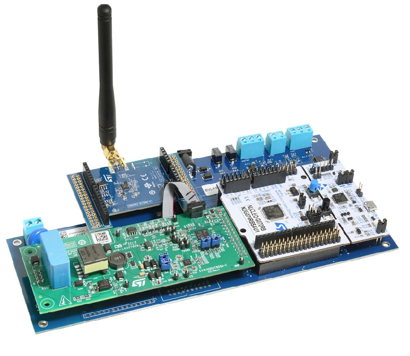
The Analog Devices Inc. CN0537 Reference Design for UL-217 Smoke Detector makes use of the EVAL-CN0537-ARDZ Evaluation Board. This Evaluation Board features a pre-mounted ADPD188BI Module, housed in a proprietary Smoke Chamber that is specifically designed to meet device and industry requirements. The internal geometry of this smoke chamber allows for the highest signal-to-noise ratio (SNR) readings and, therefore, optimal PTR values for the ADPD188BI.

When combined with the EVAL-ADICUP3029 Development Platform, the EVAL-CN0537-ARDZ Evaluation Board can be used to create a Reference Design for a smoke/fire detector circuit compliant with the ANSI/UL-217 Standard for Smoke Alarms. The UL 217 Standard includes criteria to reduce nuisance alarms and address smoke characteristics between fast-moving and smoldering fires, greatly increasing accuracy and safety.

As battery-powered devices are a common use case for smoke detectors, the Reference Design minimizes data required from the sensor and the number of computations per alarm determination. This design allows the ADPD188BI to output less data, thereby saving power and reducing consumption cycles in the microcontroller, yet still meeting the strict UL-217 specifications.

CN0537 Data & Algorithm

The Data and Algorithm Packages help complete the Reference Design. The Data Package (EVAL-CN0537-DATA) provides an extensive smoke dataset taken at UL-217 certified facilities for those who wish to develop their own algorithm and the CN0537 source code, excluding the detection algorithm. The Algorithm Package (EVAL-CN0537-ALGO) includes everything in the Data Package and a UL certified smoke detection algorithm with associated algorithm project files.

Solution Options

  • Hardware (EVAL-CN0537-ARDZEVAL-ADICUP3029) – Smoke detector reference design hardware for prototyping and solution evaluation. A tested and verified UL-217 smoke detection algorithm is embedded as part of the installer for evaluation.
    • Evaluation Board with ADPD188BI Module and Smoke Chamber
    • Microcontroller Development Board
    • UL-217 Embedded SW Executable (.hex)
    • ADPD188BI no-OS driver
  • Data (EVAL-CN0537-DATA) – CN0537 Source Code (excluding detection algorithm) plus over 1000+ sample fire/smoke datasets taken at certified UL-217 facilities for algorithm development.
    • UL-217 Test Datasets Files
    • CN0537 Source Code
    • UL-217 Test Datasets User Guide
  • Algorithm (EVAL-CN0537-ALGO) – Full source code and UL-217 8th edition tested and verified algorithm, associated project files, CN0537 source code and over 1000+ sample fire/smoke datasets to accelerate system development.
    • CN0537 Source Code including UL-217 8th Ed. Detection Algorithm (.c)
    • MATLAB and Python UL-217 Algorithm Projects
    • UL-217 Test Datasets File
    • UL-217 Algorithm Documentation
    • UL-217 Test Datasets User Guide
    • MATLAB/Python User Guide
    • 10 hours of phone support

Features

  • ADPD188BI Integrated Optical Module housed in a proprietary smoke chamber
  • Arduino Uno R3 compatible connectors
  • Selectable I2C and SPI interfaces
  • Reference Design lowers nuisance alarms using dual-wavelength detection with high SNR and dynamic range.
  • Low power circuit design for long battery life

more information: https://www.analog.com/en/design-center/reference-designs/circuits-from-the-lab/cn0537.html

LCDduino – Arduino Compatible 16X2 LCD module

The LCDduino board enables users to create many applications/projects that require a 16×2 LCD display and Arduino. The board has the exact size of 16×2 LCD and can be installed on the backside of the LCD. This is a low-cost solution that has onboard Arduino + LCD so no extra Arduino Nano or Arduino board is required. The Arduino compatible hardware includes onboard programming and boot-loader connectors, Atmega328 microcontroller, and 16×2 LCD interface. Each Arduino I/O Pin including the VCC and GND is exposed to the connectors for easy connection with sensors and other devices. The board enables the easy interface of many devices and sensors. The operating power supply is 7 to 15V DC.

LCDduino – Arduino Compatible 16X2 LCD module – [Link]

4 Channel Analog Video Distribution Amplifier

The project presented here is a low-cost video distribution amplifier capable of driving up to four video lines. The amplifier is configured with a non-inverting gain of 2. The input video source is terminated in 75 Ohms and is applied to the high impedance non-inverting input. Each output line is connected to the op-amp’s output via 75 Ohms series back termination resistor for proper cable termination. The termination resistor at the other end of the lines divides the output signal by 2, which is compensated by the gain of 2 of the op-amp. The project is built using AD8010 op-amp which is optimized for this specific function of providing excellent video performance in driving multiple video loads in parallel. Significant power is saved and heat sinking is greatly simplified because of the ability of the AD8010 to obtain this performance when running on ±5 V supply. Circuit provides 46dB of output-to-output isolation at 5Mhz driving back terminated 75 Ohms cable. Ferrite beads and high-value ceramic capacitors are used on the power supply input to reduce the noise.

4 Channel Analog Video Distribution Amplifier – [Link]

3 Channel Analog Video Splitter with Video Amplifier

If you need to drive multiple video gadgets or monitors from a single video signal source then this board is the right choice for you. This is a 3-channel video splitter with an amplifier and the circuit is built using discrete components. Q2 and Q1 act as a signal amplifier, Q3 act as output driver, trimmer potentiometer PR1 is provided to adjust the input signal swing, PR2 Trimmer is provided to set the gain of the amplifier, D1 is the power LED. The operating power supply is 12V DC and it draws 100mA current. RCA Connector J4 is the Video signal input, RCA Connector J1, J2, J3 provide the outputs. The default gain of the circuit is 4. The bandwidth is 5Mhz, input and outputs impendence are 75 Ohms. It is important to use all 3 channels at a time or change R11 to 150 Ohms if you will only use 1 x channel or 82 Ohms if 2 x channels are in use. Adjusting the board is very easy, just connect a voltmeter at the base of Q2 and adjust the PR1 so the voltage at the base of Q2 is 1V.

3 Channel Analog Video Splitter with Video Amplifier – [Link]

16 High Power LEDs Knight Rider Light – Arduino Compatible

This is a Knight Rider LED Light and it is one of the best Arduino projects for beginners. This board drives 16 high-power LEDs to turn them ON one by one sequentially. This is an open-source Arduino compatible project that contains 16 high current MOSFETs, Atmega328 microcontroller, 5V regulator etc. The gate of IRLR7843 MOSFETs is connected to the I/O pins of the Atmega328 chip. Screw terminals are provided to connect the LEDs and power supply. Additional 2 x tactile switches and one connector for analog input are provided for further experiments. Operating power supply 12V to 15V DC, each output can drive 1A constant current load (1W to 12 W LED) without cooling and load up to 2A with forced cool air.

Features

  • Operating Power Supply 12 to 15V DC
  • Load: Each Channel up to 1A Constant @ room Temperature, 2A Constant with Fan
  • LED 1W to 12W (12-24W with proper cooling with Fan)
  • PCB dimensions: 154.14 x 53.97 mm

Components and Operations

  • R1>>Pullup for Reset Pin,
  • R3, R15, R23, R31, R7, R17, R25, R33, R11, R19, R27, R35, R13, R21, R29, R37 >> Optional Series Resistors for current limiting
  • R4, R16, R24, R32, R8, R18, R26, R34, R12, R20, R28, R36, R14, R22, R30, R38 >> Current Limiting Resistors for MOSFET Gate
  • CN11, CN10, CN9, CN8, CN6, CN5, CN4, CN3, >> LED -/Cathode
  • CN2 >> LED +/Anode
  • CN1>> 12 to 15V Power Input
  • Capacitor C1, C8, C9 >> DC Bus Filter Capacitors
  • Capacitor C2, C3 >> DC Filter Capacitors for 5V Supply
  • LM78M05>> 5V Regulator provides 5V to Micro-Controller from 12V Supply
  • U1 ATMEGA328 >> Micro-Controller Loaded with Arduino Code
  • C6 >> Filter Capacitor for Ref Voltage
  • Crystal Y1, C4, C5, R6 >> Oscillator for Atmega328 Micro-Controller
  • SW1, SW2, R2, R5, R10, C7, R9, CN7, >> Optional for additional development

Arduino Pins

  • D0, D1, D2, D3, D4, D5, D6, D7, D8, D9, D10, D11, D12, D13, A0, A1 >> 16 LEDs
  • A4, A4 >> Optional Tactile Switches
  • A3>> Optional Analog Input
Note: This is an open-source Arduino compatible project, that can be used in many other applications which require 16 channel high power drivers. The board can drive 12V LEDs directly, if LEDs doesn’t have a series resistor or constant current circuitry, use series resistors R3, R15, R23, R31, R7, R17, R25, R33, R11, R19, R27, R35, R13, R21, R29, R37

Code

Arduino example code is provided, follow the instructions below to load the Arduino Code into a new ATMEGA328 chip

Schematic

Parts List

NO.QNTY.REFDESC.SUPPLIER/MANUFACTURER
110CN1,CN2,CN3,CN4,CN5,CN6,CN8,CN9,CN10,CN112 PIN SCREW TERMINAL 5.08MM PITCHDIGIKEY 277-1247-ND
28SW1,SW2,R2,R5,CN7,C7,R9,R10DNPOMIT
32C1,C8470uF/25V ELECTROLYTICDIGIKEY 1189-1869-ND
43C2,C6,C90.1uF/50V SMD SIZE 0805YAGEO
51C310uF/25V SMD SIZE 1210YAGEO
62C4,C522PF/50V SMD SIZE 0805YAGEO
716Q1,Q2,Q3,Q4,Q5,Q6,Q7,Q8,Q9,Q10,Q11,Q12,Q13,Q14,Q15,Q16IRLR7843 DPAKDIGIKEY 448-IRLR7843TRLPBFCT-ND
81R110K 5% SMD SIZE 0805YAGEO
916R3,R7,R11,R13,R15,R17,R19,R21,R23,R25,R27,R29,R31,R33,R35,R37 0E OR AS PER APPLICATION SIZE 2512DIGIKEY CR2512-J/-000ELFCT-ND
1016R4,R8,R12,R14,R16,R18,R20,R22,R24,R26,R28,R30,R32,R34,R36,R3810E 5% SMD SIZE 0805YAGEO
111R61M 5% SMD SIZE 0805YAGEO
121U1ATMEGA328 DIPDIGIKEY ATMEGA328P-PU-ND
131U2LM78M05 DPAKDIGIKEY-MC78M05CDTGOS-ND
141Y116MHZ THTDIGIKEY X1103-ND

Connections

Gerber View

Photos

Video

IRLR7843 Datasheet

High Accuracy Adjustable Overvoltage and Overcurrent Protectors using MAX17561

If you need safe power to run your project, then this circuit is a possible solution for you. This project provides protection to your system device against over-current, over-voltage, under-voltage, thermal overload, and reverse current flow control to the system device. Basically, this project can play a key role between the power supply and the sensitive system device, where the system device will be protected against the above conditions. When there is a change other than the set parameters the circuit will disable the output and go in retry mode, until the condition is as per the set value. The project is built using MAX17561 chip. Refer to the datasheet to get further information. Refer to the schematic shown below and have look at some of the panorama of the project explained below.

Important Features:

  • Adjustable overvoltage protection range is between 6V and 36V
  • Adjustable undervoltage protection range is between 4.5V and 24V
  • Overvoltage-lockout (OVLO) thresholds are set using external resistors R1 and R7
  • Undervoltage-lockout (UVLO) thresholds are set using external resistors R2 and R8
  • Programmable Forward-Current Limit: 0.7A to 4.2A (±15% Accuracy) is set using R9 (R9 13K = Approx. 1Amp)
  • Reverse Current Flow Control Input
  • Thermal Overload Protection
  • Dual Enable Inputs: EN and High Voltage HVEN
  • Fault Indicator Output. FLAG goes low when the fault duration exceeds the blanking time, reverse current is detected, the thermal-shutdown mode is active, OVLO threshold is reached, or SET-Current is connected to GND.
  • Reverse-Current Enable Input. Open the Jumper J3 enables reverse-current flow protection. Close the Jumper J3 (RIEN to logic-high) to disable the reverse-current flow protection
  • EN: Close the Jumper J2 to enable the input (Active-High Enable Input)
  • HVEN: Close the Jumper J1 to activate HVEN High voltage Enable (36V Capable Active-Low Enable Input)
  • PCB dimensions: 70.01 x 51.28 mm

Switch Control

There are two independent enable inputs (HVEN and EN) for the devices. HVEN is a high-voltage-capable input. Toggle HVEN or EN to reset the fault condition once a short circuit is detected and the devices shut down.

  • Jumper J1 Close, Jumper J2 Open >> Switch Status ON
  • Jumper J1 Close, Jumper J2 Close>> Switch Status ON
  • Jumper J1 Open, Jumper J2 Close>> Switch Status ON
  • Jumper J1 Open, Jumper J2 Open>> Switch Status OFF
  • Jumper J3: Open enables reverse-current flow protection. Close the Jumper J3 (RIEN to logic-high) to disable the reverse-current flow protection

Adjusting Parameters

Refer to the figure which explains the formula to set the overvoltage, Under voltage, and Load Curren:

Testing the board

Perform the following steps to test the project, Close Jumper 1 and Jumper 2, connect the voltmeter on output, Connect 5V DC power supply to VCC and GND pin of CN3. Use another variable power supply, adjust the voltage to 19.5V and connect this power supply to input CN1, verify that output is 19.5V DC and Flag pin is high. Gradually increase the DC power supply voltage and verify that OUT voltage goes down and Flag pin is low when input reached approximately 33V. Gradually decrease voltage on the DC power supply and verify that OUT comes back and Flag pin is high again when the input reaches approximately 32V. So the safe range of voltage input is 19.5V to 32V with Load Capacity 1 A. This project can work with a single power supply if Fault/Flag information is not required.

Default internal factory-pre-set internal OVLO threshold is 33V (typ.) and the pre-set internal UVLO threshold is 19.2V (typ.) The current-limit protection is set using R9 to 1A, but current limit protection is programable up to 4.2A, once current reaches the threshold, the MAX17561 turns off the output after the 20.7ms (typ) blanking time and stays off during the retry period.

Auto retry Current Limit

When the current threshold is reached, the tBLANK timer begins counting. The FLAG asserts if the overcurrent condition is present for tBLANK. The timer resets if the overcurrent condition disappears before tBLANK has elapsed. A retry time delay, tRETRY, is started immediately after tBLANK has elapsed and during tRETRY time, the FETs are off. At the end of tRETRY, the FETs are turned on again. If the fault still exists, the cycle is repeated and the FLAG stays low. When the fault is removed, the FETs stay on. If the die temperature exceeds +150NC (typ) due to self-heating, the MAX17561 enables thermal shutdown until the die temperature drops by approximately 30NC . The autoretry feature reduces the system power in case of overcurrent or short-circuit conditions. During tBLANK time, when the switch is on, the supply current is held at the current current limit. During tRETRY time, when the switch is off, there is no current through the switch. Thus, the output current is much less than the programmed current limit.  With a 20.7ms (typ) tBLANK and 600ms (typ) tRETRY, the duty cycle is 3.3%, resulting in a 96.7% power savings.

Reverse-Current Block Enable (RIEN)

This feature enables reverse-current protection and disables reverse-current flow from OUT to IN. The reverse-current block feature is useful in applications with inductive loads.

Schematic

Parts List

NO.QNTY.REFDESC.MANUFACTURERSUPPLIERSUPPLIER'S PART NO
12CN1,CN22 PIN SCREW TERMINAL 5.08 MM PITCHPHOENIX CONTACTDIGIKEY277-1247-ND
21CN34 PIN HEADER 2.54MM PITCHWURTHDIGIKEY732-5317-ND
31C10.47uF/50V SMD SIZE 0805YAGEO/MURATADIGIKEY
41C24.7uF/50V SMD SIZE 1210 OR 1206YAGEO/MURATADIGIKEY
51C30.1uF/50V SMD SIZE 0805YAGEO/MURATADIGIKEY
61C410uF/50V SMD SIZE 1210YAGEO/MURATADIGIKEY
72C5,C6100uF/50V SMD ELECTROLYTICNICHICONDIGIKEY493-9425-1-ND
83J1,J2,J3JUMPER/SHUNTSULLING DIGIKEYS9001-ND
92R1,R22.2M 5% SMD SIZE 0805YAGEO/MURATADIGIKEY
103R3,R5,R6100K 5% SMD SIZE 0805YAGEO/MURATADIGIKEY
111R410K 5% SMD SIZE 0805YAGEO/MURATADIGIKEY
122R7,R80E SMD SIZE 0805YAGEO/MURATADIGIKEY
131R913K 1% SMD SIZE 0805YAGEO/MURATADIGIKEY
141U1MAX17561MAXIMDIGIKEYMAX17561AUD+-ND

Connections

Gerber View

Photos

Video

MAX17561 Datasheet

“EnerCera” Battery Series helps develop Maintenance-Free IoT Devices

NGK INSULATORS, LTD., announced that it has commenced collaboration with Renesas Electronics Corporation, on promoting the widespread adoption of maintenance-free IoT devices. As the first phase of collaboration, NGK and Renesas jointly-developed a reference design for a wireless air quality sensing system that will contribute to the realization of a decarbonized society. The system was developed by combining NGK’s EnerCera battery series and Renesas’ RE Family of ultra-low power microcontrollers (MCUs).

Data collection and utilization are considered to be the most effective means of realizing a productive life or addressing social issues. Meanwhile, actions to achieve the decarbonization of society have been gathering momentum on a global basis. For example, Japan and many other countries around the world have adopted the goal of achieving net zero greenhouse gas emissions by 2050. Therefore, these countries will be required to reduce their power consumption even as they deploy numerous IoT devices for data collection purposes. To realize such a society, there is a need to develop maintenance-free IoT devices that can be powered by trace amounts of electric power obtainable from energy sources in the environment, such as peripheral light, heat, and vibration energy. It also requires for a device that do not require battery replacement.

1. Can be charged efficiently with tiny power from Solar Cell. 2. Can output high power to drive wireless communication IC etc. 3. Can drive device stably even during the night.

EnerCera battery series is a lithium-ion rechargeable battery featuring a high capacity, low resistance, and long life despite having a compact, ultra-thin body. EnerCera battery series is ideal as a power source for maintenance-free IoT devices, since it can efficiently charge itself with a weak current and output an intermittent large current to drive functions such as sensing and communication. To power a device with the electric power stored in the battery, an MCU that links the battery with sensor ICs, communication ICs, and other components is needed. For this reason, NGK has developed a reference design for promoting the widespread adoption of maintenance-free IoT devices, together with Renesas’ RE Family MCUs that realize industry-leading ultra-low power consumption.

“We are confident that the combination of NGK’s battery technology and Renesas’ ultra-low power consumption technology will accelerate the widespread adoption of battery maintenance-free IoT devices,” said Makoto Mizokuchi, Head of Low Power Products Department at Renesas.

“I’m convinced that NGK’s collaboration with Renesas will promote the development of maintenance-free IoT devices, thereby helping to solve social issues while realizing a decarbonized society.” said Iwao Ohwada, Vice President and General Manager, Advanced Device Components Div., Electronics Business Group at NGK.

As the first phase of collaboration, NGK and Renesas jointly-developed a reference design for wireless outdoor air quality sensing systems powered by solar cells. Monitoring pollution levels in outdoor air provides valuable insights on the associated health effects from elevated levels. Conventional sensing systems have presented problems such as requiring power cables due to their large power consumption and thus being subject to restrictions on sites where they could be installed. The combination of ultra-low power RE MCUs and low resistance, high-capacity EnerCera batteries will enable constant measurement of outdoor air quality indexes at all times, even with only trace amounts of intermittent electric power obtainable from the solar cells. This will allow monitoring of the degree of atmospheric pollution without having to devote time and effort to power cable wiring and battery replacement. The system can also support long-distance radio communications such as low-power wide-area (LPWA) network technologies, enabling centralized management of measurements from numerous sensors in the field.

Not only for environmental monitoring but also a variety of other fields, NGK and Renesas will continue to jointly-develop reference designs to realize the widespread adoption of maintenance-free IoT devices that combine the EnerCera battery series and RE Family MCUs.

ST’s STEVAL-USBPD27S To Speed Up The Built Time of Fast-Charging USB Power Adapters

NB_STEVAL-USBPD27S_0221

USB has evolved over the last few years with the latest launch of the ST’s standalone VBUS-based controller. To help build a compact and efficient power adapter that provides up to 27W with zero-power operation when no cable is connected, STMicroelectronics has unveiled a new reference design with Programmable Power Supply (PPS). All new ST’s STEVAL-USBPD27S solution introduced has the PPS capabilities through three-stage architecture. Apart from the power supply section and the power control stage is the digital control stage that is built around the STM32G071KB Arm Cortex-M0+ MCU that controls the USB Type-C connector and the Power Delivery 3.0 communication protocol.

SL-USBPD27S

One of the key technical benefits lies in the specific algorithm running on the MCU that can control the VBUS on the secondary side, and is “compliant to USB Type-C and Power Delivery and PPS specifications”. The onboard flyback converter combines a high-performance, low-voltage PWM controller chip on the same package. For Type-C port protection, the solution is provided with a single chip solution – TCPP01-M12 – that ensures robustness and protection.

As an MCU-based solution, the reference design gives users extra flexibility to implement additional customized application layers and to incorporate ongoing improvements as the USB Power Delivery standard evolves.

STEVAL-USBPD27S

The STEVAL-USBPD27S is USB power delivery 3.0 compliant with a wide range of input voltages. This is capable of delivering:

  • Two fixed PDOs: 5V@5A, 9V@3A
  • Two APDOs (PPS): 5VProg@5A, 9VProg@3A

This compact form factor of 59 x 35 x 21mm in size and 10.2 W/inch3 that has a standard output power of 27 W. With the STCH03 PWM controller offers several advantages to the solution featuring “high-voltage start-up circuitry, primary-side constant-current output regulation, and advanced power management”.

For more information on the reference design to accelerate the design of a power adapter that delivers an output of up to 27W, visit the press release by the company. The ST’s STEVAL-USBPD27S is expected to be sold at a price of $95.00.

Note: All the images were taken from the STMicroelectronics website.

STMicroelectronics Evaluation Boards to Boost the G3-PLC Hybrid Connectivity into Smart Devices

ST8500 ecosystem

A couple of weeks back STMicroelectronics announced its new addition to the development ecosystem for its ST8500 programmable power-line communication (PLC) modem chipset – STMicroelectronics Evaluation Boards. For those new to the connectivity of smart-grid and IoT devices, G3-PLC Hybrid is a:

“standard that offers extended capabilities for smart grid and IoT applications in one seamlessly managed network over both wired and wireless media”.

ST8500 is a high-performance, programmable power-line communication (PLC) modem system-on-chip that has the capability to run any PLC protocol in the frequency band up to 500 kHz. This system-on-chip is integrated with the ARM 32-bit Cortex-M4F core clocked up at 200 MHz maximum frequency.

G3-PLC hybrid is different in terms of how each device in the mesh network can use PLC as well as RF for communication. This allows several systems with ST8500 system-on-chip to “select the powerline or wireless channel autonomously and change dynamically to ensure the most reliable connection”.

ST’s hybrid protocol stack is based on G3-PLC, IEEE 802.15.4, 6LowPAN and IPv6 open standards. By embedding support for RF Mesh in the physical (PHY) and data-link layers, the ST8500 combines the strengths of powerline and wireless mesh networks for communication between smart nodes and data collectors.

STMicroelectronics Evaluation Boards

The release includes the launch of two evaluation boards that operate at RF frequency of 868MHz and 915MHz. The EVLKST8500GH868 kit is designed as per the 868MHz RF band, while the EVLKST8500GH915 kit works in the 915MHz band. When comparing both of the boards, they have the same technical specifications except for the expansion board for the RF transceiver.

For the smart connectivity application, both the evaluation boards are provided with the ST8500GH-MB baseboard that offers RS485 and CAN bus connectivity. Apart from this, at the heart of the board is a PLC module based on ST8500 and STLD1.

According to the press release, both the STMicroelectronics evaluation boards are now available at ST and the distributors, priced at $250.

Note: All the images were taken from the STMicroelectronics website.

Shenzhen LC Technology’s Cherry Pi PC V7 is a Replica of Orange Pi PC

Cherry Pi PC V7

We saw Orange Pi board, a clone of a Raspberry Pi featuring almost all functionalities similar to Raspberry Pi 2. At present, Shenzhen LC Technology has launched a clone of Orange Pi PC known as Cherry Pi PC V7 featuring the same quad-core processor. That is Allwinner’s quad-core H3 SoC supporting the Linux environment.

The Allwinner’s quad-core H3 SoC has an architecture similar to the quad-core Cortex A7 CPU. This is a 32-bit processor working at a frequency of 2GHz. Hence, the H3 processor is compatible to provide a 4K smart TV set-top box solution. The processor also supports H.265 video decoding at a rate of 30fps. The SoC also comes with the Allwinner’s latest SmartColor display engine. Thus, the device is for video/display types of use cases.

Allwinner's H3 SoC

Technical Specifications of Cherry Pi PC V7:

  • The board features Allwinner H3 SoC which is a quad-core Cortex A7 CPU-based 32-bit processor.
  • Graphic support by Arm Mali-400 MP2 GPU working at 600MHz along with 256KB L1 and 1MB L2 cache
  • The memory includes 512MB to 1GB DDR3 SDRAM
  • The Storage includes a MicroSD slot and an optional 8GB eMMC
  • Networking with 10/100Mbit Ethernet (RJ45) with an optional RTL8189 2.4GHz 802.11b/g/n WiFi chip and iPEX WiFi antenna
  • The camera interface includes a 24-pin CSI interface
  • I/O ports include 2x USB 2.0 Host ports, 1x Type-C USB power input, 28 GPIOs connectors, Debug 3-pin UART head, and IR receiver

Labelled Cherry Pi PC V7 board

The power supply for the Cherry Pi PC V7 is a 5V Type-C USB input with a 2A current rating. The dimension of the board is 85 x 56mm, which is exactly similar to Raspberry Pi 2 and almost equal to 85 x 55mm Orange Pi PC. The weight of the Cherry Pi PC V7 is around 55g which is heavier than 38g Orange Pi PC and 42g Raspberry Pi 2. This could be due to the additional components and features like optional 8GB eMMC flash and RTL8189 2.4GHz 802.11b/g/n WiFi chip plus iPEX WiFi antenna.

There is also an option for expansion with a 40-pin header compatible with Raspberry Pi B for more applications. It is compatible with many operating systems including Android, Ubuntu, Debian, etc which makes its software support quite flexible. Cheery Pi PC V7 can support a wide range of applications including TV box, robot, game console, wireless network player, and facial recognition system.

The board comes in two variations with respect to the RAM size and additional features. The board with 512MB RAM is available for $16.5 USD. Whereas, the board with 1GB RAM, 8GB eMMC flash, and WiFi is available for $28.20 USD. The Cherry Pi PC V7 boards are available on the Aliexpress website. For more information visit the official product page. Images and technical specifications have been also taken from the product page.

via LinuxGizmos

TOP PCB Companies