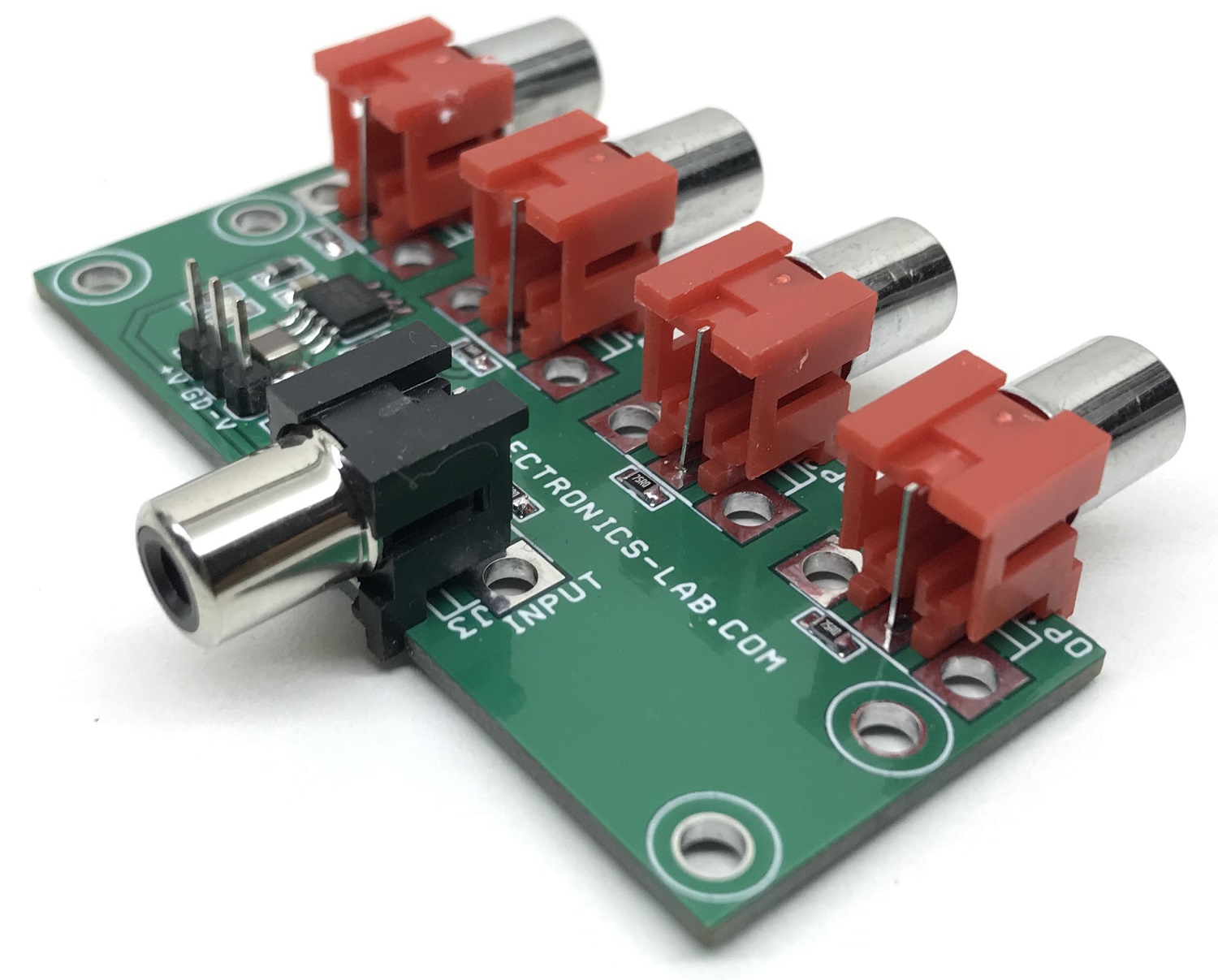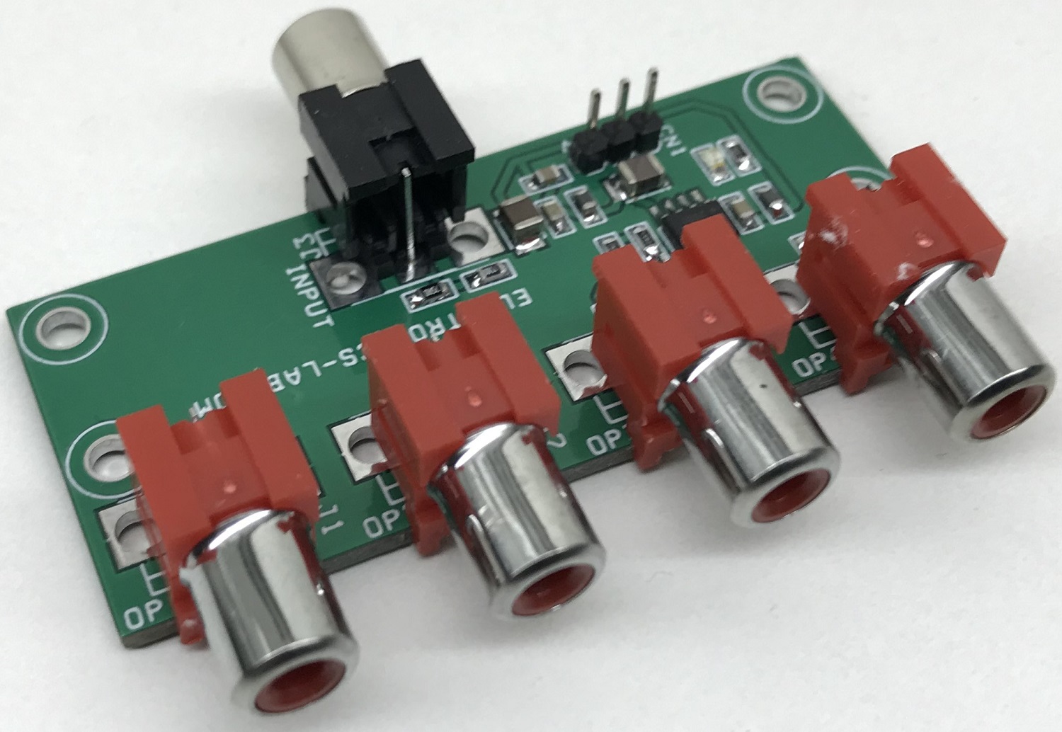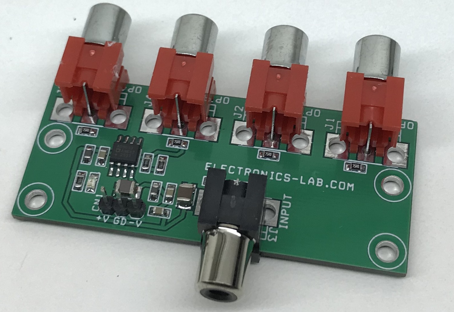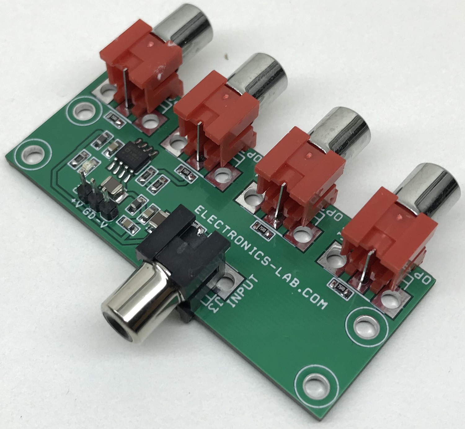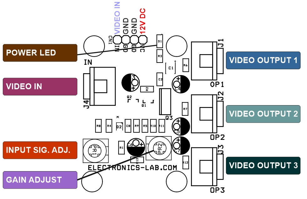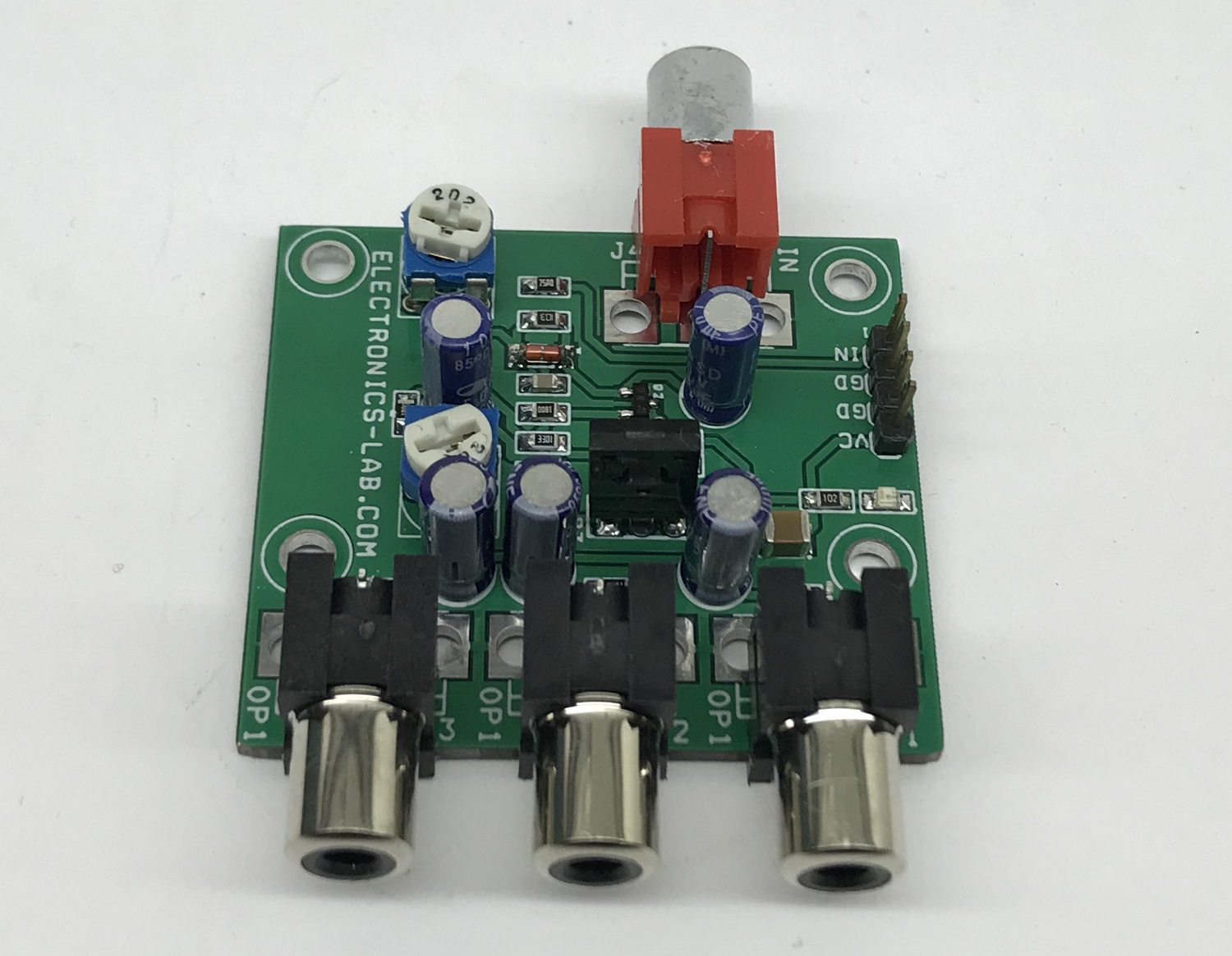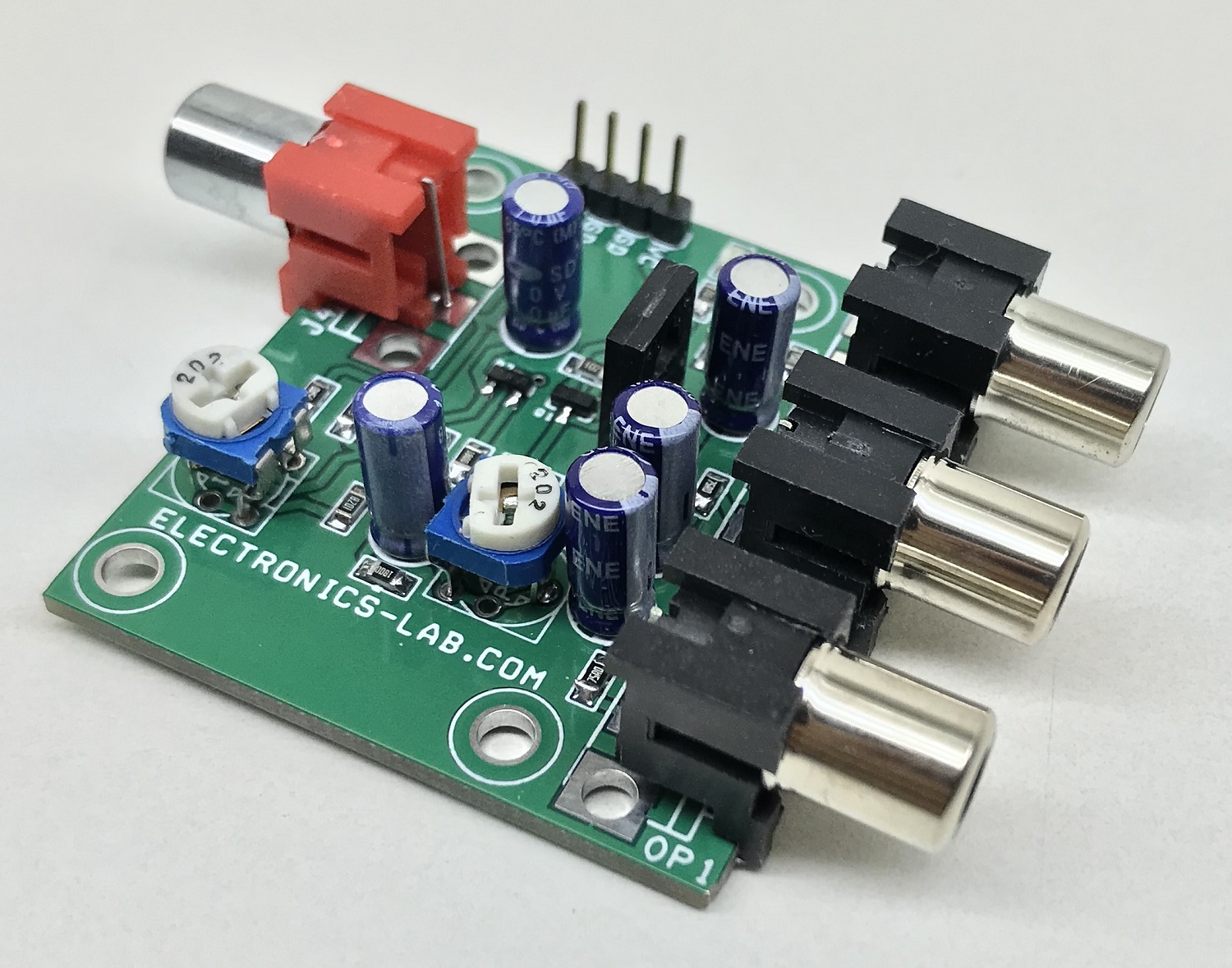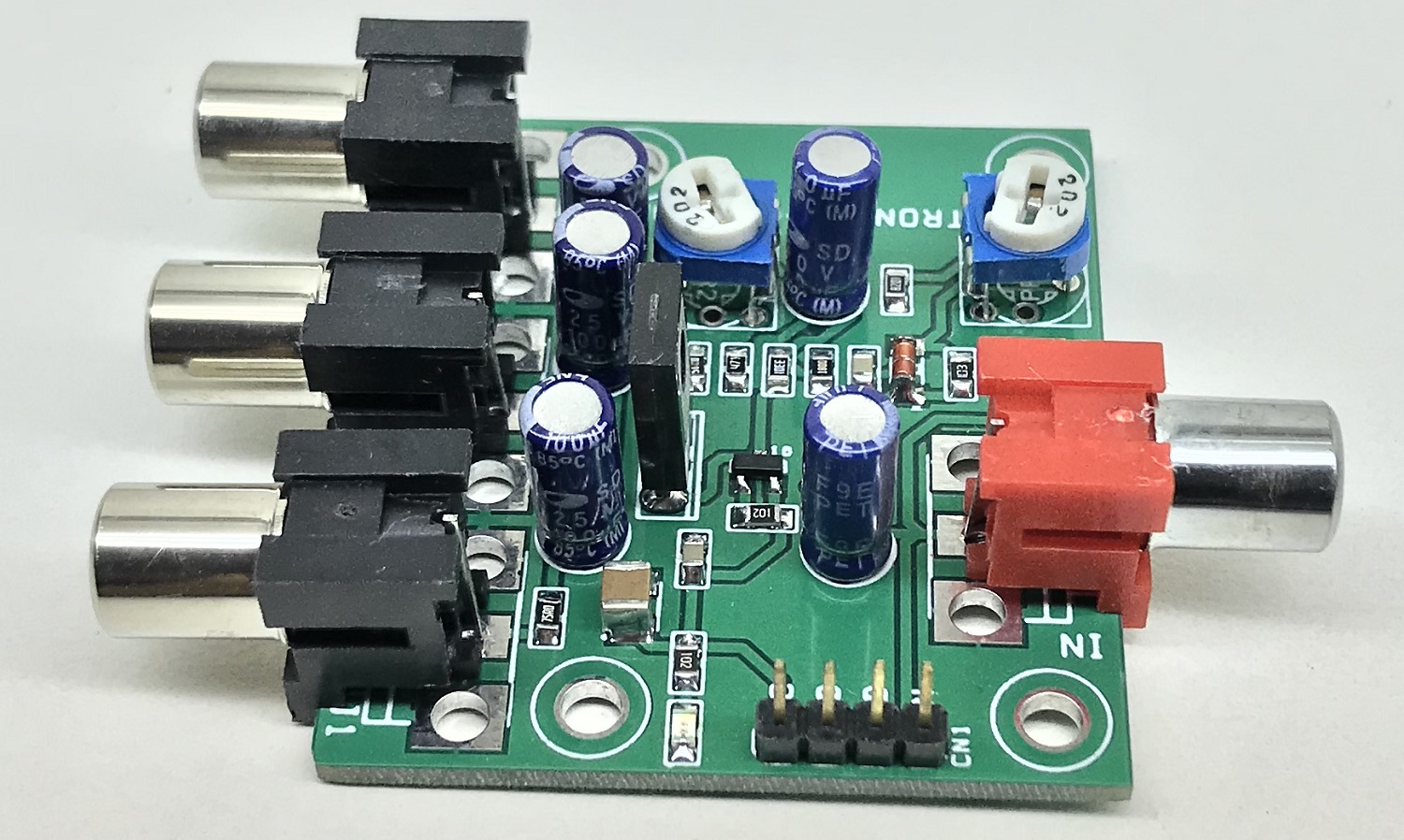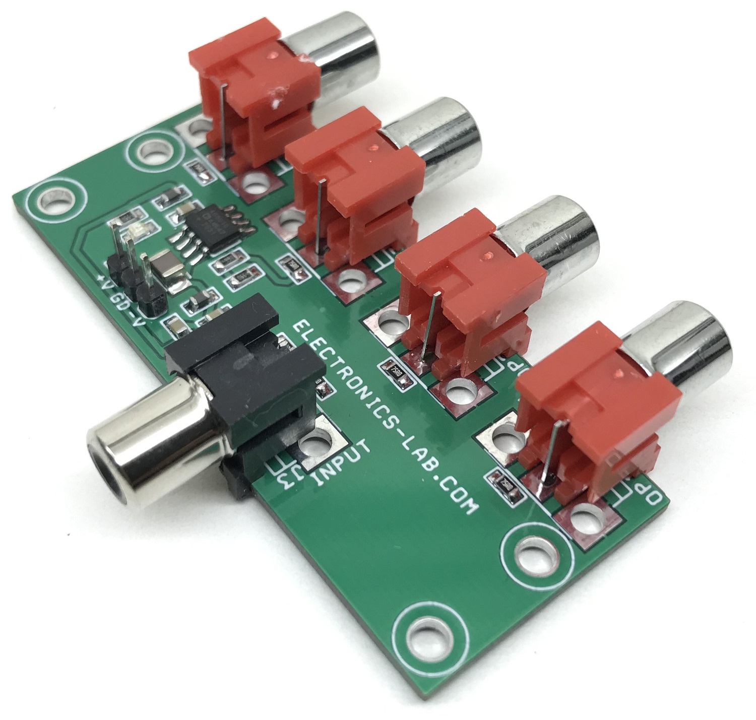
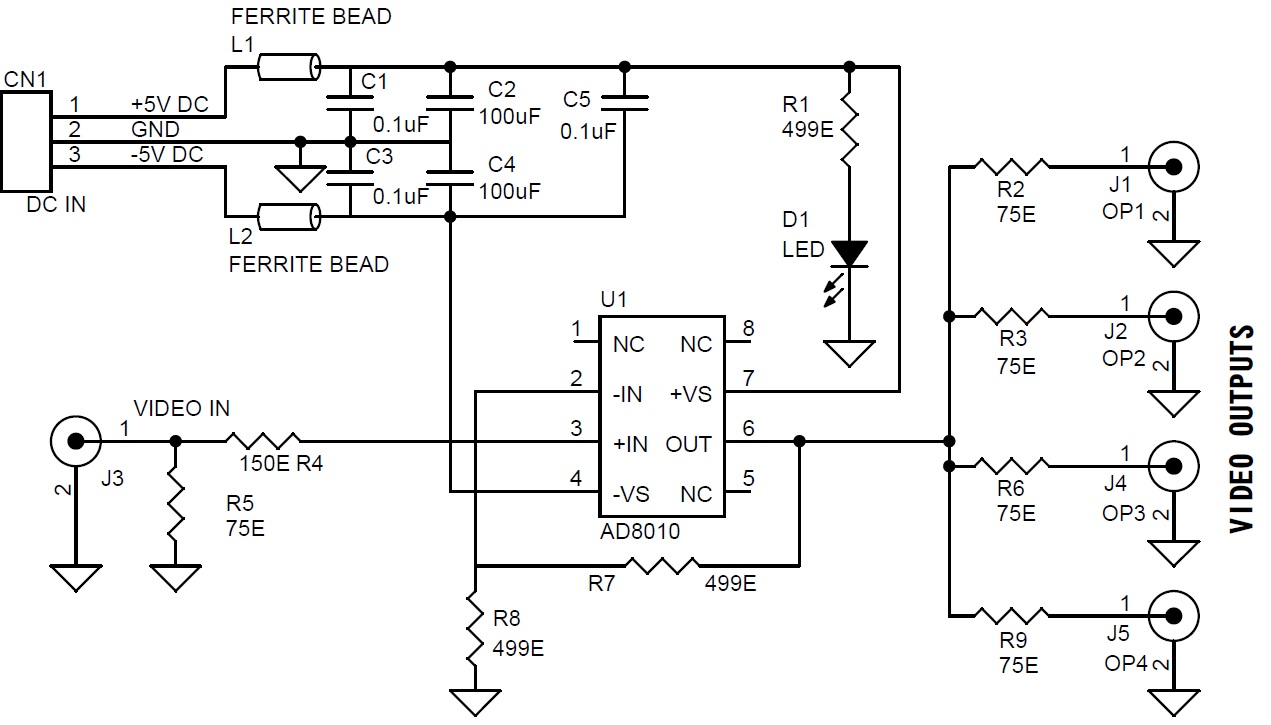
The project presented here is a low-cost video distribution amplifier capable of driving up to four video lines. The amplifier is configured with a non-inverting gain of 2. The input video source is terminated in 75 Ohms and is applied to the high impedance non-inverting input. Each output line is connected to the op-amp’s output via 75 Ohms series back termination resistor for proper cable termination. The termination resistor at the other end of the lines divides the output signal by 2, which is compensated by the gain of 2 of the op-amp. The project is built using AD8010 op-amp which is optimized for this specific function of providing excellent video performance in driving multiple video loads in parallel. Significant power is saved and heat sinking is greatly simplified because of the ability of the AD8010 to obtain this performance when running on ±5 V supply. Circuit provides 46dB of output-to-output isolation at 5Mhz driving back terminated 75 Ohms cable. Ferrite beads and high-value ceramic capacitors are used on the power supply input to reduce the noise.
Features
- Power Supply +/-5V DC (Dual 5V Symmetrical Power Supply) @ 20mA
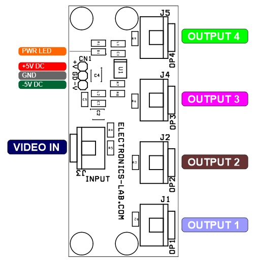
- RCA Connector for Video In
- 4 x RCA Connector for Video Output
- Power LED
- PCB Dimensions 69.06 x 29.69 mm
The AD8010 is a low-power, high current amplifier capable of delivering a minimum load drive of 175 mA. Signal performance such as 0.02% and 0.03° differential gain and phase error is maintained while driving eight 75 Ω back terminated video lines. The current feedback amplifier features gain flatness to 60 MHz and –3 dB (G = +1) signal bandwidth of 230 MHz and only requires a typical 15.5 mA supply current from ±5 V supplies. These features make the AD8010 an ideal component for Video Distribution Amplifiers.
Schematic
Parts List
| NO. | QNTY. | REF. | DESC. | MANUFACTURER | SUPPLIER | SUPPLIER PART NO |
|---|---|---|---|---|---|---|
| 1 | 1 | CN1 | 3 PIN MALE HEADER 2.54MM PITCH | WURTH | DIGIKEY | 732-5316-ND |
| 2 | 3 | C1,C3,C5 | 0.1uF/50V SMD SIZE 0805 | YAGEO | ||
| 3 | 2 | C2,C4 | 100uF/10V SMD SIZE 1210 | KEMET | DIGIKEY | 399-11631-1-ND |
| 4 | 1 | D1 | LED RED SMD SIZE 0805 | OSRAM | DIGIKEY | 475-1415-1-ND |
| 5 | 1 | J1 | RCA FEMALE CONNECTOR | KYCON INC | DIGIKEY | 2092-KLPX-0848A-2-R-ND |
| 6 | 1 | J2 | RCA FEMALE CONNECTOR | KYCON INC | DIGIKEY | 2092-KLPX-0848A-2-R-ND |
| 7 | 1 | J3 | RCA FEMALE CONNECTOR | KYCON INC | DIGIKEY | 2092-KLPX-0848A-2-R-ND |
| 8 | 1 | J4 | RCA FEMALE CONNECTOR | KYCON INC | DIGIKEY | 2092-KLPX-0848A-2-R-ND |
| 9 | 1 | J5 | RCA FEMALE CONNECTOR | KYCON INC | DIGIKEY | 2092-KLPX-0848A-2-R-ND |
| 10 | 2 | L1,L2 | FERRITE BEAD SMD SIZE 0805 | WURTH | DIGIKEY | 732-1613-1-ND |
| 11 | 3 | R1,R7,R8 | 499E 1% SMD SIZE 0805 | YAGEO | ||
| 12 | 5 | R2,R3,R5,R6,R9 | 75E 1% SMD SIZE 0805 | YAGEO | ||
| 13 | 1 | R4 | 150E 1% SMD SIZE 0805 | YAGEO | ||
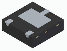
| 14 | 1 | U1 | AD8010 SO IC | ANALOG DEVICES | DIGIKEY | AD8010ARZ-ND |
Connections
Gerber View
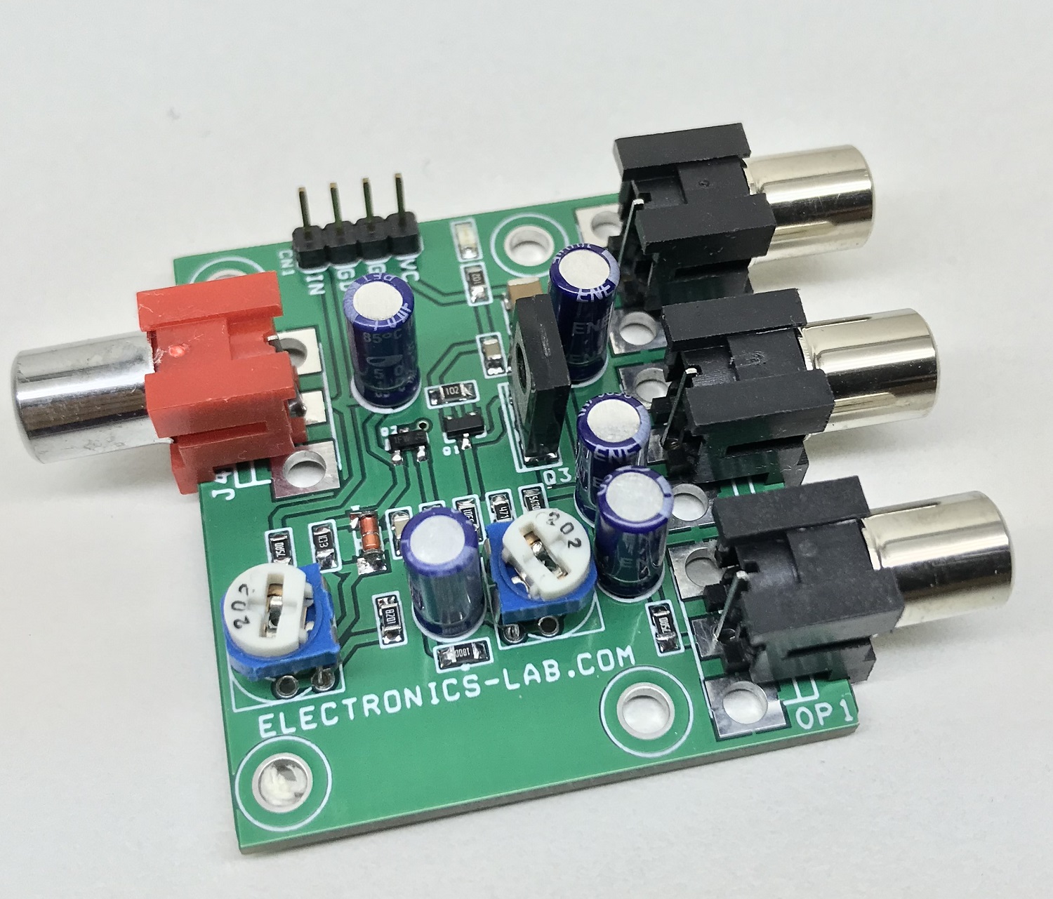
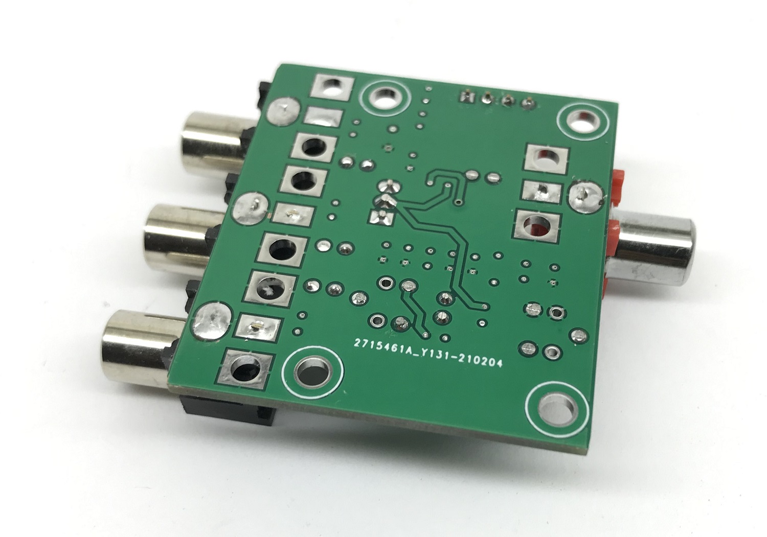
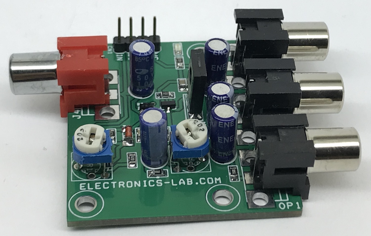
Photos