RGBDuino UNO and RGBDuino RGB Shield: Add Light and Questionable Arduino PCB

Now, from my writing experience here at eLab, I have dealt with some funny and interesting concepts, but nothing quite like what I am about to show you. But bear with me here, aside from the questionably looking electronics you are about to glance, there might be something useful to light up your Arduino projects. So, take this article with a grain of salt, as things will get very weird, very fast.

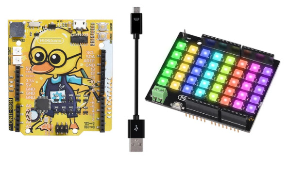
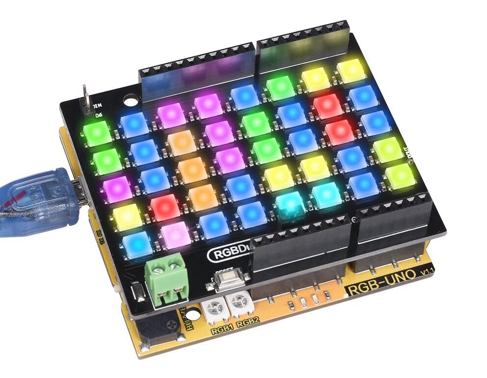
So, what is there so special about the RGBDuino? Firstly, we are talking about an RGB shield for Arduino, constituted by 40, individually addressable, RGB LEDs. It allows for a flexible 5 and 3.3 V inpt logic, as well as operate under the 3.5 to 5.3 V range, so nothing very limiting there. Speaking of limitations, you only need one pin to control it, and you also have a 24-bit color resolution, which is really good. It can be powered via the Arduino directly (with a mere 2 A of maximum operating current, are you sure you want to do that?), or via an external source. Regarding safety, it incorporates a reverse polarity protection diode for the external power port. Being compatible with the Arduino interface, it makes an ideal candidate for your projects where lightling is important. The last two things to take into consideration are a digital output connection, for you to expand the 40 LEDs to more, if you desire, and the adition of a reset button, so that you do not injure yourself trying to reach for the button on the bottom of the board, if necessary.

The RGBDuino shield
The RGBDuino shield

Now, everything discussed so far does not seem ridicule, in any way, so let us embrace the weirdness that accompanies this product. You can only get the RGBDuino shield if you get a very questionably looking Arduino UNO compatible board, the RGBDuino UNO. Do not get me wrong, it is a fully-fledge and dignified version of an Arduino, but they went with a very unusual looking PCB, which comes in the form of an anime woman (and I describe: half-naked, holding a soldering iron, the right way at least) named Jenny, or an intelectual-looking duck with glasses and dungarees. Why am I complaining? They look amazing! Well, they did not name the duck, and that bothers me.

Is this the part where I get fired?

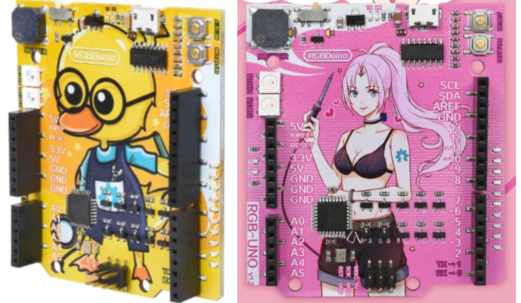
After what we have seen so far, you may be wondering: what’s the use of an image on top of a PCB if I am going to hide it with a shield? Well, do not hide it. It is worth much more, use an Arduino for the shield instead, and get a transparent case to the Arduino board! Lastly, as I said, you can only get this in bundle with Jenny or “duck”, and it will be $18.67, which is not bad, considering the creativity put into it (and the fact that LED shields are quite expensive).

When I said to not hide the board, here is a suggestion

Watchy: The Open-Source E-Paper Watch

The good thing about Tindie is that allows all of us to creatively showcase and sell our most promising projects. I cannot stress how awesome it is to have such a market online, for our inventions! As a good example of its usefulness, we will glance today at an e-paper watch that has the potential to do so much, the Watchy!

Created by SQFMI and hosted on Tindie, the Watchy is an open-source (hardware and software) e-paper watch, that consists of a single PCB, with the connectors for a battery and an 200 x 200, e-paper display. While its display gives you a unique vibe, not really usual in a watch, the wearable is also a very promissory development platform, due to its hardware and the easiness to program it to incorporate different functionalities: it can be stated as an innocent watch, but can go far beyond that scope. Besides that, its appearance can be customized with no fuss, through 3D printed cases and different watch straps.

Watchy, dissected
Watchy, dissected

By taking a deeper dive into its internals, you can see why we have done nothing but compliment this innofensive timepiece. At the heart of the PCB there is an ESP32, giving you the Wi-Fi and Bluetooth capabilities most smartwatches rely upon these days. When it comes to sensors and actuators, you are well served: a motor, some tactile buttons, an accelerometer… and more obviously, the serial-USB adapter for programming / charging and an RTC (because at the end of the day, it is still intended to be a watch).

Taking a look at the specs, here is what you will find:

  • Ultra-low-power, 1.54″ e-paper display, with a resolution of 200 x 200 and wide viewing angles
  • ESP32-PICO-D4 MCU, with Wi-Fi and Bluetooth connectivity
  • 3-axis accelerometer with gesture detection capability
  • Vibration motor
  • 4x tactile buttons, located on the sides
  • Open-source hardware and software architecture; many watch faces + examples available on GitHub and 3D case designs + watch straps
Watchy and its inner beauty

As you can see here, the Watchy has the potential both as a product and also as a handheld development platform, for you to unleash your creativity upon. It even has a website entirely dedicated to it! We do not see many alternatives on the market, beside some Arduino-based projects, but this one here is something else, in my humble opinion. One thing I do not know for sure is the e-paper display, I do like a bit of color, so I would like to see them release an alternative display, just because I think it would bring even more attention to it. Lastly, let us discuss price: for $44.99 (in sale right now) you can get the complete Watchy. If you are int he market for something similar, it is a no-brainer!

Even the case is cooler than the cool kids

Meet Qomu – A complete SoC that easily fits inside a USB port

Tomu family of USB devices has recently introduced a small form factor board that is not only a single MCU or an FPGA, but a complete System-on-chip that fits easily inside a USB port.

The tiny compact board called Qomu, is a capable USB device that integrates an EOS S3 low-power MCU and an eFPGA with 100% open source tools. The MCU can run up to 80 MHz while the embedded FPGA has about 2,400 effective logic cells and up to 64 Kbits of available embedded RAM.

Whether it’s a glue logic for a new peripheral or an accelerated machine learning classifier that you need, the EOS S3 SoC makes it easier to make fine-grained design tradeoffs. Contained within the chipset is a 16-channel DMA for efficient data movement, configurable serial peripheral interface, I2C controller interfaces and two dedicated multipliers that can be used to offload math-intensive functions.

Qomu is compatible with a number of open source tools, so you don’t have to worry about being an expert with Verilog before you can use the FPGA. They include nMigen for Python-to-FPGA design flow, Zephyr, FreeRTOS, SymbiFlow and Renode. The board also features about 16 Mbit flash, 3x RGB LEDs and up to 4x capacitive touchpads.

Some of the key features and specifications of this board include:

  • QuickLogic EOS S3 SoC that integrates:
    • An Arm® Cortex-M4F MCU that can be clocked at up to 80 MHz
    • embedded FPGA with 2,400 effective logic cells
    • 512 KB system memory
    • 64 Kbits of embedded RAM with about eight RAM/FIFO controllers
    • 2x dedicated multipliers for offloading math-intensive functions
    • 16-channel DMA (for efficient data movement within the chipset)
    • Configurable SPI controller and peripheral interface
    • I2C controller interface
    • Ultra low Power consumption (in µW)
  • 16 Mbit Flash
  • 3x LEDs (R G B), and,
  • 4x capacitive touch pads

The board which can be used with low-power machine learning-capable devices, is a perfect EOS S3 development kit to get started with. It is the kind of device that you can carry anywhere even while you are still at your project. Just slot it into any USB Type-A port and it becomes easy to move around.

The board project is still looking for community funding and is yet to be launched on Crowdsupply, but you can sign up here to receive updates and notifications when it finally does. Hopefully that should come up sometime around the beginning of next year.

More details about the board can also be found here: https://www.crowdsupply.com/quicklogic/qomu

Headphone Amplifier For DAC Converter

This is a headphone amplifier project for audio digital-to-analog converters (DACs) with differential voltage outputs. This circuit converts the differential voltage output of the DAC to a single-ended, ground-referenced signal and provides the additional current necessary for low-impedance headphones. Project is built using OPA1688 low distortion, high-drive Sound Plus audio amplifier. The circuit tested with dual +/-5V DC supply, and it can drive a load 16 Ohms to 600 Ohms. Headphone amplifier provides an output 50mW into 32 Ohms. Signal for the right channel and left channel input is applied to the amplifier through connectors CN1and CN3, respectively.

The positive input from the source connects to the pin labelled I1+/I2+, the negative input from the source connects to the pin labelled I1-/I2-, and the ground connection from the source connects to the center pin of CN1 and CN3, labelled GND. Stereo 3.5mm Female EP socket provided to interface the Headphone.  The project supports headphone of 16 Ohms, 32 Ohms and 600 Ohms, output power of the circuit depends on impedance of headphone, for example, a pair of headphones with a 95dB/mW sensitivity given a 3mW input signal produces a 100dB SPL. If the headphones have a nominal impedance of 32 Ω, then the voltage and current from the headphone amplifier (voltage=310mV RMS and current 9.86mA RMS)

Features

  • Supply +/-5V DC
  • Differential Input Signal
  • Output Power 50mW in to 32 Ohms Headphone
  • Head-Phone Loads: 16 Ohms, 32 Ohms, 600 Ohms
  • Frequency Response 20Hz to 20Khz
  • PCB Dimensions 42.23 x 20.16 mm

Schematic

Parts List

Connections


Gerber View

Photos

Video

OPA1688 Datasheet

Texas Instruments UCC27288 Half-Bridge Driver

Texas Instruments UCC27288 Half-Bridge Driver is a robust N-channel MOSFET driver with a maximum switch node (HS) voltage rating of 100V. It allows for two N-channel MOSFETs to be controlled in half-bridge or synchronous buck configuration based topologies. Its 3.5A peak sink current and 2.5A peak source current, along with low pull-up and pull-down resistance, allows the UCC27288 to drive large power MOSFETs with minimum switching losses during the transition of the MOSFET Miller plateau. Since the inputs are independent of the supply voltage, UCC27288 can be used in conjunction with both analog and digital controllers. Two inputs are completely independent of each other and therefore provide added control design flexibility.

The input pins, as well as the HS pin, can tolerate significant negative voltage, which improves system robustness. The inputs are completely independent of each other. This feature allows for control flexibility where two outputs can be overlapped by overlapping inputs if needed. Small propagation delay and delay matching specifications minimize the dead-time requirement, which improves system efficiency. Under-voltage lockout (UVLO) is provided for both the high-side and low-side driver stages forcing the outputs low if the VDD voltage is below the specified threshold. No integrated bootstrap diode allows users to use an application-appropriate external bootstrap diode. Texas Instruments UCC27288 is offered in a SOIC8 package to improve system robustness in harsh environments.

Features

  • Drives two N-channel MOSFETs in high-side low-side configuration
  • 16ns typical propagation delay
  • 12ns rise, 10ns typical, fall time with 1800pF load
  • 1ns typical delay matching
  • Configurable external bootstrap diode
  • 8V typical undervoltage lockout
  • Absolute maximum negative voltage handling on inputs (–5V)
  • Absolute maximum negative voltage handling on HS (–14V)
  • 3.5A sink, 2.5A Source output currents

more information: https://www.ti.com/product/UCC27288

OSRAM Opto Semiconductors OSIRE® E3323 RGB LEDs

OSRAM Opto Semiconductors OSIRE® E3323 RGB LEDs offer individually addressable LED chips for maximum flexibility in terms of color point, driver selection, and interconnection. These LEDs provide an integrated Dot Matrix Code (DMC) that provides the measurement data of luminous intensity, forward voltage, and color coordinates. The E3323 LEDs feature thin-film/thinGaN chip technology and a white SMD package with colorless clear silicone resin. These LEDs incorporate close chip arrangements in the triangle and series configurations. The E3323 LEDs are AEC qualified and can be traced via device ID. These LEDs are designed for colored ambient lighting in automotive applications and interior illumination like an ambient map.

Features

  • Compact size of 3.3mm x 2.3mm
  • Reduced height of 0.7mm
  • Close chip arrangement in the triangle and series configurations
  • DMC carrying device ID
  • Improved traceability via device ID
  • Measurement data at 10mA and 50mA
  • Thinfilm/thinGaN chip technology
  • 2kV ESD according to the ANSI/ESDA/JEDEC JS-001 (HBM, Class 2)
  • AEC-Q102 qualified
  • White SMD package with colorless clear silicone resin

more information: https://www.osram.com/os/products/product-promotions/led-for-automotive-industry-and-consumer-applications/product_promotion_osire.jsp

Always-on Low-power Gas Sensing with 10+ Year Coin Cell Battery Life Reference Design

The TIDA-00756 TI Design uses nano-power operational amplifiers, comparators, system timers, temperature sensors, and the SimpleLink™ ultra-low power 2.4-GHz wireless microcontroller (MCU) platform to demonstrate an ultra-low power carbon monoxide detector implementation. These technologies lead to an extremely long battery life, over 10 years with a standard CR2032 lithium ion coin cell battery, which could be used for applications including gas detection or air quality monitoring. The carbon monoxide detector has sensitivity up to 1000 ppm with a standby current of 1.07-µA. The design guide includes techniques for system design, detailed test results, and information to get the design up and running quickly.

Features

  • Use of nano-power analog ultra-low-power design resulting in 10-year battery life from single CR2032 coin cell
  • Carbon monoxide gas sensor and analog logic always powered on to enable continuous monitoring and fast response times
  • Bluetooth® Low Energy (BL) wireless connectivity reduces installation costs and allows multiple sensors to communicate with single host
  • Self-check and end-of-life monitoring recognizes malfunctioning gas sensor and reports status every five minutes (configurable)
  • Carbon monoxide gas detection range of 0 to 1000 ppm with ±15% accuracy

more information: https://www.ti.com/tool/TIDA-00756

2Gb, 4Gb, and 8Gb LPDDR4 SDRAMs with low power usage

Alliance Memory 2Gb, 4Gb, and 8Gb LPDDR4 SDRAMs Offer Low Power Consumption to Increase Battery Life in Mobile Electronics; Devices Combine Low-Voltage Operation of 1.1V With Fast Clock Speeds of 1.6GHz for increased Efficiency and Performance

The 2Gb AS4C128M16MD4-062BAN, 4Gb AS4C256M16MD4-062BAN and AS4C128M32MD4-062BAN, and 8Gb AS4C256M32MD4-062BAN provide lower power consumption and faster speeds than the previous-generation LPDDR3 SDRAMs. The devices are available in 200-ball FBGA packages.

The devices offer low-voltage operation of 1.1V/1.8V to prolong battery life in portable electronics for the consumer and industrial markets. For higher efficiency for advanced audio and high-resolution video in embedded applications, the LPDDR4 SDRAMs provide clock speeds of up to 1.6GHz for high transfer rates of 3.2Gbps. For automotive applications, the AEC-Q100 qualified products can operate over an extended temperature range of -40°C to +105°C.

The LPDDR4 SDRAMs are organized as 1 channel (AS4C128M16MD4-062BAN and AS4C256M16MD4-062BAN) and 2 channels (AS4C128M32MD4-062BAN and AS4C256M32MD4-062BAN) per device. Individual channels consist of eight banks of 16 bits. The components feature fully synchronous operation; programmable read and write burst lengths of 16, 32, and on the fly; and selectable output drive strength. An integrated temperature sensor controls the self-refresh rate.

Alliance Memory’s LPDDR4 SDRAMs have been developed to provide a reliable drop-in, pin-for-pin-compatible replacement for numerous similar solutions in high-bandwidth, high-performance memory system applications — eliminating the need for costly redesigns and part requalification.

Key Specifications and Benefits:

  • On-chip ECC
  • AEC-Q100 qualified
  • Low-voltage operation of 1.1V/1.8V
  • Fast clock speeds of 1.6GHz
  • Extremely high transfer rates of 3.2Gbps
  • Automotive A2 Grade, temperature range -40°C to +105°C
  • Eight internal banks per channel
  • x32 for 2-channels per device (AS4C128M32MD4, AS4C256M32MD4)
  • x16 for 1-channel per device (AS4C128M16MD4, AS4C256M16MD4)
  • Programmable read and write latencies
  • Programmable and on-the-fly burst lengths (16 and 32)
  • Selectable output drive strength
  • On-chip temperature sensor to control self-refresh rate
  • Offered in the 200-ball FBGA package

Samples and production quantities of the new LPDDR4 SDRAMs are available now, with lead times of eight weeks.

More information: www.alliancememory.com

DIY Air Quality Monitor measures PM2.5, CO2, VOC, Ozone, Temp & Humidity

Dejan over at HowToMechatronics shared detailed instructions on how to build your own air quality monitor:

Have you ever wondered about the quality of the air you are breathing, or maybe, why you sometimes feel sleepy in the office or tired in the morning even after sleeping all night? Poor air quality can lead to many negative health effects as well as can cause tiredness, headaches, loss of concentration, increased heart rate and so on. Monitoring the quality of the air may actually be more important than you realize. So, in this tutorial we will learn how to build our own Air Quality Monitor which is capable of measuring PM2.5, CO2, VOC, Ozone, as well as temperature and humidity.

DIY Air Quality Monitor measures PM2.5, CO2, VOC, Ozone, Temp & Humidity – [Link]

TOP PCB Companies