Digital Pressure Gauge 0 to 10kPa (0 to 1.75 psi) with OLED display

The project presented here is a Digital Pressure Gauge using an OLED display. The measuring range of this unit is 0 to 10kPa (0 to 1.75 psi). Additional this compact open-source hardware is Arduino compatible. This board can be used for measuring low pressure up to 1.75psi with great accuracy. The board contains an MPXV5010DP analog pressure sensor, ATmega328 microcontroller, and 0.96 inch I2C OLED display. The board can also be connected to other high-pressure analog sensors from NXP. The operating power supply is 5V DC and it requires 25mA of current. The output of the pressure sensor is 0.2V to 4.75V that proportional to applied pressure. The analog output of the sensor is connected to the A0 analog pin of the ATmega328 chip. A 4 pin header connector is provided to mount the OLED display. A4, A5, VCC, and GND pins used to interface the display. You can download the sample Arduino code to test the board.

Digital Pressure Gauge 0 to 10kPa (0 to 1.75 psi) with OLED display – [Link]

Low-Cost Room Thermometer Using 16×2 LCD and Atmega328

This is an easy to build small size and low-cost room thermometer. The project consists of LM35 analog temperature sensor, 16×2 LCD, and an Atmega328 chip. This compact board is Arduino compatible and provided with an onboard connector for Boot-Loader burning and Arduino IDE programming. Board also has 2 additional connectors for analog input and digital I/O. Trimmer potentiometer PR1 helps you to adjust the contrast of the LCD.  Example Arduino Code for the thermometer is available as a download to test the board. The example will display the temperature value in Celsius as well as Fahrenheit. The operating voltage of the circuit is 5V DC and it draws approx. 35mA of current with backlight LED ON. Scale factor/Output of LM35 is 10mV/Centigrade. This board can also be used in other Arduino applications that require a 16×2 LCD and I/O Pins.

Low-Cost Room Thermometer Using 16×2 LCD and Atmega328 – [Link]

Smart RGB LED Light Stick – Arduino Compatible

This is a Smart LED light stick that contains 20 x WS2812B single wire addressable full colors RGB LEDs and Atmega328 microcontroller. These full colors chainable intelligent RGB LEDs work with a single wire addressable protocol thus they require a micro-controller to generate the pulse train to control the colors and flashing effects. Refer to the datasheet of LEDs to decode the various colors flashing effects. The operating supply of the circuit is 5V DC with a maximum current of 1A.

Example Arduino code will help you to test the board. The Atmega328 chip can be programmed using the Arduino platform, we have used the DIP package of the microcontroller for easy programming using Arduino UNO and insertion of the programmed chip to the LED stick.

Smart RGB LED Light Stick – Arduino Compatible [Link]

Advantech Launches AIMB-233 “THIN” Mini-ITX Industrial Motherboard with 8th Gen. Intel® Core™

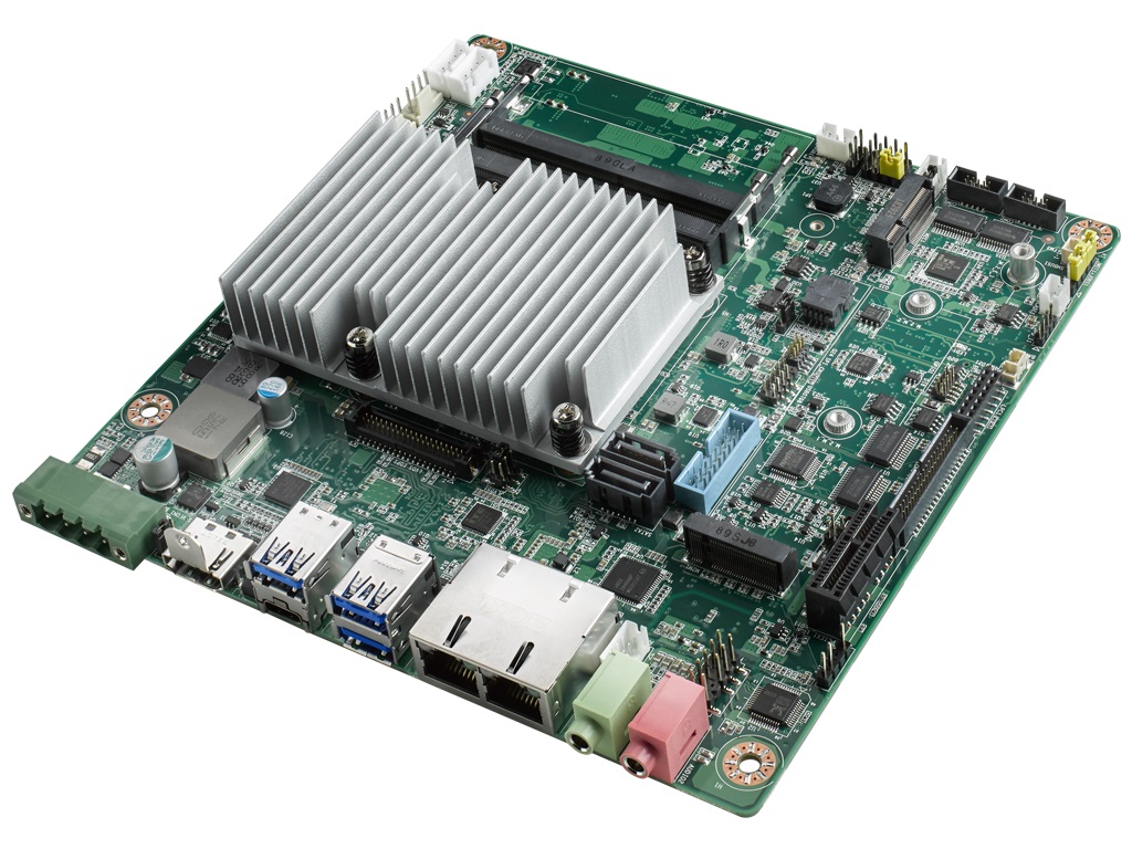
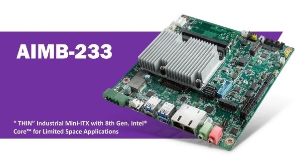
Advantech, a leading provider of industrial motherboards, is pleased to release AIMB-233, a low-profile industrial-grade “THIN” Mini-ITX motherboard to enable graphics processing and computing power in limited space applications. AIMB-233 is powered by an 8th Gen. Intel® Core™ Processor, features diverse I/O ports and utilizes an optimized thermal solution. With an overall height of just 25 mm, this motherboard is an excellent choice for slim design applications in Human Machine Interfaces (Panel PCs), mobile devices, nursing carts with integrated wall displays, patient care systems and medical imaging processing.

Featuring Dual Ethernet and Numerous I/O for Diverse Applications

Advantech AIMB-233 features multiple high-speed I/O — including 8 USB ports (1x type C USB 3.1, 3x USB 3.1, 2x USB 3.0, 2x USB 2.0), 2x SATA III, PCIe x1, 1x M.2 M-Key, and 1x M.2 E-key (optional full-size MiniPCIe) — to consolidate legacy and modern peripheral devices on a motherboard. Additionally, this motherboard has 8-bit digital programmable I/O, 6x COM ports (one port for RS-232/422/485) and a 2W dual-channel audio amplifier. AIMB-233 is further equipped with dual Gigabit Ethernet ports that deliver up to 1000 Mbps of bandwidth for two network segment applications. These features allow AIMB-233 to support a wide range of peripherals and network connections in a myriad of applications.

Designed to Empower High-End Graphics and Low-Latency Storage

AIMB-233 supports high-speed interfaces via USB Type-C Alt to offer USB, DisplayPort and HDMI. USB Type-C Alt supports a max. 4906 x 2034 @60Hz resolution to deliver excellent graphics to medical imaging processing. The M.2 M-key socket enables the use of high-performance SSD to deliver reliable high-speed processing for critical data operations.

AIMB-233 Key Features:

  • Equipped with 8th Gen. Intel® Core™ i / Celeron mobile processors
  • Dual channel DDR4-2400 260-pin SODIMM up to 32 GB
  • 8x USB, 2x SATA III, 6x COM, 1x M.2 M-key/8-bit GPIO, 1x M.2 E-key
  • Triple display by Type C Alt. + HDMI + LVDS (or eDP*)
  • FCC/CB Class B Certified and ESD level 4 (Contact 8 KV)
  • 12~24V DC power input
  • Pre-installed WISE-DeviceOn software for remote monitoring and management
  • Note: BOM optional function by request.

Advantech AIMB-233 industrial-grade “THIN” Mini-ITX motherboard is available now. For further information or Advantech Industrial Motherboard products, please contact your local sales support team, an authorized channel partner or visit www.advantech.eu. Learn more as well about Advantech’s local customization options under http://bit.ly/AdvantechDMS.

Rapid Deployment in Harsh Environments

AIMB-233‘s fanless design reduces time-to-market for System Integrators. This motherboard provides powerful and stable computing performance in a wide temperature range (-20~70°C) and in harsh environments. Additionally, its 12-24V DC-in feature supports flexible system power designs for Medical and Industrial Automation applications.

Enhanced Security Solution for Medical Applications

Medical devices, including radiation/diagnostic equipment, monitoring devices, and patient information systems require advanced security capabilities. AIMB-233 motherboard features secure hardware and software to protect data and patient privacy. Its software, UEFI Secure Boot and boot guard, secures pre-boot environments, while its hardware supports optional TPM 2.0 for enhanced data protection.

IAM-20680HP – High-Performance Automotive 6-Axis MotionTracking Device

TDK Invensense’s 6-axis MotionTracking device enables manufacturers to eliminate the need for system-level integration of discrete devices

TDK Invensense’s IAM-20680HP is a 6-axis MotionTracking device for automotive applications that combines a 3-axis gyroscope and a 3-axis accelerometer in a small 3 mm x 3 mm x 0.75 mm (16-pin LGA) package. It also features a 4096-byte FIFO that can lower the traffic on the serial bus interface and reduce power consumption by allowing the system processor to burst read sensor data and then go into a low-power mode. Its 6-axis integration enables manufacturers to eliminate the costly and complex selection, qualification, and system-level integration of discrete devices, guaranteeing optimal motion performance.

  • Digital-output X-, Y-, and Z-axis angular rate sensors (gyroscopes) with a user-programmable full-scale range of ±250 dps, ±500 dps, ±1000 dps, ±2000 dps, and integrated 16-bit ADCs
  • Digital-output X-, Y-, and Z-axis accelerometer with a full-scale programmable range of ±2 g, ±4 g, ±8 g, ±16 g, and integrated 16-bit ADCs
  • User-programmable digital filters for gyroscope, accelerometer, and temperature sensor
  • Embedded self-test
  • Wake-on-motion interrupt for low power operation of applications processor
  • Reliability testing performed according to AEC-Q100: PPAP and qualification data available upon request
  • Final test at -40°C, +25°C, and +105°C
  • Burn-in in production

more information: https://invensense.tdk.com/products/motion-tracking/6-axis/iam-20680/

Meet PiFinger – World’s First Fingerprint HAT for Raspberry Pi

SB Components, the company behind several ambitious, Raspberry Pi-based products like PiTalk phone, LapPi laptop, and PiArm robotic arm, has weighed in with the world’s first fingerprint HAT for Raspberry Pi, called PiFinger.

PiFinger has a structure that is designed with powerful peripherals to provide stable performance. It is programmed to compare and register up to 24 fingerprints, as well as recognize algorithms for fingerprint comparison. The HAT features a powerful 2D capacitive fingerprint area sensor with a hardened surface that can detect and measure anything that is conductive or has a dielectric. The sensor has an active scanning area of 8.8 mm x 8.8 mm with a 176 x 176 pixels and 408 dpi spatial resolution. The sensor also has an enhanced ESD immunity of + / – 15kV, and a low-power consumption rate in both normal and standby modes. Other specifications include 8-bit pixel value / 256 gray levels, high-speed SPI interface, 1:1 image ratio of length to width, and up to 2 megapixels per second image capture speed.

Despite its really low power consumption (supplied with 3.3V and 5V), the PiFinger is a very powerful device with high efficiency. PiFinger incorporates onboard Nuvoton MCU with an on-chip crypto-accelerator, Cortex-M23 TrustZone and XOM memory protection security technologies which makes it powerful to perform its task efficiently. The device also has other features including a reset button, an 0.91″ OLED display for displaying messages like “Access Granted” or “Access Denied”, 40-pin GPIO header, and three LEDs. The HAT is also touted for its wide temperature range and robust coating material.

PiFinger can be connected directly via USB to PC as a biometric security device or controlled by the MCU/processor over a serial UART interface. If you want to use and control it with RPi or PC application then you need to connect it to the PC first by a USB for UART.

PiFinger is small in size and compatible with all variants of Raspberry Pi. It can be used for a couple of tasks like attendance management system, door authentication, Lock/Unlock Raspberry Pi, etc.

PiFinger is available for order on Kickstarter through December 24th starting at $60, and will ship in February next year. There’s however a $100 package of the PiFinger that bundles an RPi 4 with 2GB RAM, another package that bundles the HAT with a 5-inch, HDMI connected screen for $107, and a fourth package that has both a RPi 4 and a display for $134.

Further details on the open-source device may be found on the PiFinger Kickstarter page.

LM5161 Based DC-DC Bias Power Supply for Solar Projects

There’s great news for you if you are one of those looking for a DC-DC bias supply with small outputs that you can use for your projects. Brian Cornell, an electronic enthusiast with an interest in power management, has built a DC-DC bias power supply using Texas Instruments’ LM5xxx series IC.

“I often need a DC-DC bias supply for my projects that supplies a few outputs, typically 5V & 12V, only a few watts, and most often non-isolated. There are a lot of COTS [Commercial Off-The-Shelf] choices in this range with unit costs under $20.00 but I often find that they don’t meet some key spec,” writes Cornell as he talks about the motivation behind his project. “Most often it is the dual output requirement combined with a Vin range from ~10V ~ 25V. In the past, I’ve worked around this by going with a single 12V output followed by a 5V linear regulator. Not a big deal but it is more parts to source & place along with a bit more dissipation.”

Cornell oftentimes has kicked around the idea of designing one that has some configuration flexibility but this time he obviously did not want to spend the time since a 5W design can demand just as much time as a 500W.

“I found myself needing one for my solar charger and this time the itch got the better of me. I had one of TI’s LM5017 evaluation boards lying around and decided to give it a go.”

The LM50xx family of regulators is non-isolated buck regulators known for a number of incredible features including simplicity, low-cost wide Vin range, and output configuration flexibility. Cornell started by adding extra windings to obtain outputs at different voltages which could be tied to the primary ground or isolated. He then used a constant on-time PWM scheme to eliminate the traditional compensation network required to close the control loop. The artifact of the constant on-time control scheme however showed the control loop requires some ripple for stability (a contributing factor is the small output capacitance) so he went ahead to add a small LC filter to the output to solve this problem.

Cornell, however, noted that the LM5017 has a current limit of 600mA which would not be enough to handle the power required of both outputs, but one can use the LM5161 which is a higher power sibling of LM5017 that integrates more features.

SPECIFICATIONS (as configured)

  • Vin 10.6 – 30V DC (tested to 25V)
  • # Outputs – 2 (V1, V2)
  • V1 – +5V, 300mA, 1.5W, non-isolated
  • V2 – +12V, 200mA, 2.4W, [non]-isolated
  • Output ripple: V1 < 10mV P-P, V2 < 20mV P-P
  • Regulation: V1 – 1%, V2 – 11% (over Vin range, V1 & V2 @ full load)
  • Transient response (3mS pulse, 20%->100% load)
    V1 – 250uS
    V2 – 960mV droop
  • Peak efficiency: 84.5% (V_in=14V, V1 & V2 @ full load)
  • Average efficiency: 83% (over Vin range, V1 & V2 @ full load)
  • Low efficiency: 81.5% (Vin=10.6V, V1 & V2 @ full load)
  • Radiated EMI: not tested
  • Operating temperature: -40C (characterized) – +85C (tested)
  • Soft start
  • Protection: over current, thermal shutdown
  • Dimensions(LWH): 4.7cm x 2.3cm x 1.6cm (1.85″ x 0.91″ x 0.63″)
  • Unit cost: $23.00 (excluding assembly time & materials)

Cornell has released the schematic and KiCad project files as well as supporting data for the board, but you may want to read the full details of the project before going ahead to build one for yourself. The design, inherent to the controller architecture, has a lot of “problems” including secondary regulation, conditional stability, and the current limit scheme used but “as long as these are understood,” he says, it can be used successfully.

Further details including file downloads can be found on his project page on Hackaday.io by Brian Cornell

Quantum Engineering’s Hackboard is a Windows 10 Pro SBC with Optional 4G or 5G connectivity

Single-board computers (SBCs) have gained a tremendous boost over the years. More and more powerful processors have made their way into the embedded computing market and this has caused the single board computers of today to become so powerful that they have almost the capability of modern-day PCs and tablets.

Companies on the other hand are beginning to take full advantage of emerging technologies in order to keep pace with the ever-growing customer needs. One such is Quantum Engineering who is preparing to launch a very powerful but affordable Intel Celeron-powered single-board computer (SBC) that offers optional 4G or 5G cellular connectivity and is capable of running Windows 10 IoT or the more demanding desktop builds. Whether you are a DIY maker, system integrator, solution provider, or an IoT (Internet of Things) developer, Hackboard is your powerful development board that can empower creation and accelerates your productivity.

“Hackboard is a new SBC that was designed from the ground up to be one of the most powerful and affordable Windows-capable, Intel-based computers ever. With optional 4G or 5G connectivity, it is ideal for students, teachers, families, makers, and hobbyists alike,” says the company.

The board aims at helping more people connect to one another and to information, be it from home, or school, or office. It is a high performing platform that is well suited to a large and diverse set of possible projects like home automation, smart home peripherals, weather stations, industrial monitors and controls, media servers, games consoles, and digital audio hubs.

Quantum Engineering is yet to release the full specifications of the board which is said to be considerably larger than Arm-based rivals like the Raspberry Pi 4, but here are some of the features and specifications that it has:

  • CPU: 64-bit, dual-core Intel Celeron processor running at up to 2.8GHz
  • Intel UHD graphics processor
  • 4 GB DDR4 RAM
  • 64 GB on-board eMMC storage with an M.2 slot for up to two additional terabytes of storage
  • 3x USB 3.0 ports
  • 1x 40-pin general-purpose input / output (GPIO) header
  • HDMI 2.0 output
  • Headphone jack
  • Optional 4G or 5G cellular connectivity, and,
  • An included Power Supply

There is no word yet on how much the board is going to be sold but the company claims that it is going to be affordable even as it is powerful and reliable.

More information on the board can be found on the project’s page on Crowd Supply.

The crowdfunding campaign is yet to go live, but you can sign up and get the chance to receive updates and be notified when it finally does.

Digital Pressure Gauge 0 to 10kPa (0 to 1.75 psi) with OLED display

The project presented here is a Digital Pressure Gauge using an OLED display. The measuring range of this unit is 0 to 10kPa (0 to 1.75 psi). Additional this compact open-source hardware is Arduino compatible. This board can be used for measuring low pressure up to 1.75psi with great accuracy. The board contains an MPXV5010DP analog pressure sensor, ATmega328 microcontroller, and 0.96 inch I2C OLED display. The board can also be connected to other high-pressure analog sensors from NXP. The operating power supply is 5V DC and it requires 25mA of current. The output of the pressure sensor is 0.2V to 4.75V that proportional to applied pressure. The analog output of the sensor is connected to the A0 analog pin of the ATmega328 chip. A 4 pin header connector is provided to mount the OLED display. A4, A5, VCC, and GND pins used to interface the display. You can download the sample Arduino code to test the board.

Programming the board with Arduino IDE

After assembly of the board, the ATmega328 chip will need boot-loader burning and Arduino code uploading.

Refer to the wiring diagram for boot-loader burning and Arduino code uploading. More info available here for Boot-loader/Arduino programming.

Features

  • Operating Supply 5V DC @ 25mA
  • Measuring range 0 to 10kPa (0 to 1.75 PSI)
  • PCB Dimensions 44.61MM X 27.31MM

Schematic

Parts List

Connections

Gerber View

Photos

Video


MPXV5010DP Datasheet

Win an Xbox Series X or PlayStation 5 in OEMsecrets.com competition

In oemsecrets.com‘s latest competition, they’ve teamed up with Traco Power to give 2 lucky subscribers the chance to win the latest PS5 and Xbox Series X consoles worth $500 each.

PS5 is given away, but Xbox is still in the game!

oemsecrets.com is a comparison search engine which helps buyers and engineers quickly find the best price and inventory for millions of electronic parts from the industry’s leading distributors. Simply enter an MPN to compare prices and inventory from distributors including Mouser, Avnet, Arrow, Future, Farnell, RS, and many more.


How to Enter

  • Option 1 – Fill out the form using the following link
  • Option 2 – Share and like the posts on the following platforms and receive an additional entry into the competition. Share using Facebook, Twitter, Linkedin.

NOTE: This giveaway is in partnership with Traco Power, a leading manufacturer of DC/DC converters, AC/DC switching power supplies, and customer-specific power supply solutions. Traco and oemsecrets.com also partnered to power the ‘Where to Buy’ feature on tracopower.com, which shows customers on product pages which distributors have inventory available, with a buy link to purchase directly from the distributor’s shopping cart to order [See example].

TOP PCB Companies