Stretchable Conductors Maintain Conductivity Under 700% Strain

Conductive materials change their properties under strain or stretching. The electrical conductivity decreases and resistance increases with stretching. The US Air Force Research Laboratory (AFRL) is working with liquid metal systems that can autonomously change the structure to become better conductors in response to strain.

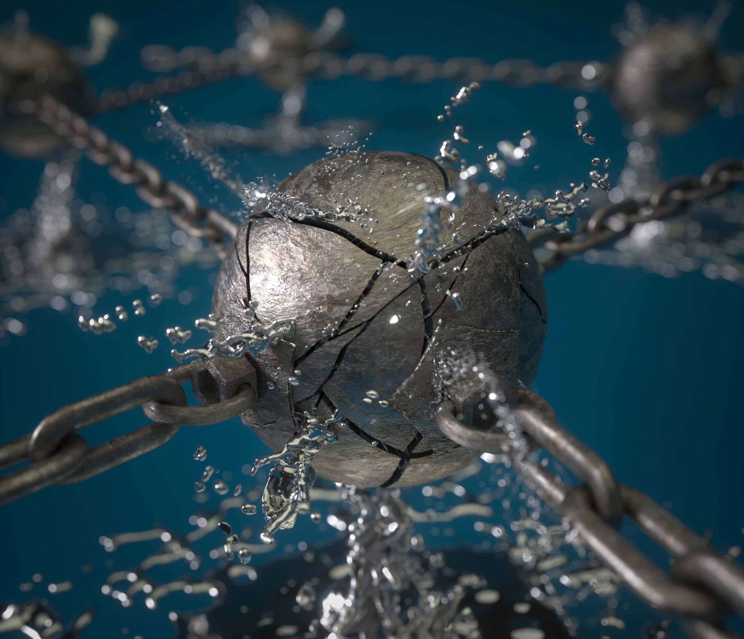
Polymerized Liquid Metal Networks, the material developed by AFRL scientists, can show very odd even opposite properties while under strain. These flexible liquid-metal networks can sustain up to 700% of the strain from the normal stage and still, can keep the resistance virtually the same and still return to their original state. It is all possible due to the self-organized nanostructure within the material that performs these responses automatically.

This response to stretching is the exact opposite of what you would expect,

Dr. Christopher Tabor, AFRL lead research scientist on the project said.

Typically a material will increase in resistance as it is stretched simply because the current has to pass through more material. Experimenting with these liquid-metal systems and seeing the opposite response was completely unexpected and frankly unbelievable until we understood what was going on.

This new material has many applications in next-generation wearable electronics where the material could be combined into a long-sleeve garment. Previous stretchable electronics had a problem with transferring power through the shirt and across the body in a way that bending an elbow or rotating a shoulder would change the power transferred.

The researchers are currently working with both private companies and universities to explore further development of the circuit system. In this case, they will enable the integration of these materials into textiles that can serve to monitor and augment human performance.

When the liquid metal particles are strained, the particles tear open and liquid metal spills out and maintains the conductivity and stretchability. During each stretching cycle, the conductivity increases and returns to normal. As claimed, there is no detection of fatigue in the base material after 10,000 cycles. This new nanomaterial holds the potential for a ton of feasible applications in the future. Most beneficial will be wearable electronics and health monitoring devices.

More information can be found in this article published on Advanced Materials.

[photo credits: Advanced Materials – Volume 31, Issue 40]

Smart RGB LED Light Stick – Arduino Compatible

This is a Smart LED light stick that contains 20 x WS2812B single wire addressable full colors RGB LEDs and Atmega328 microcontroller. These full colors chainable intelligent RGB LEDs work with a single wire addressable protocol thus they require a micro-controller to generate the pulse train to control the colors and flashing effects. Refer to the datasheet of LEDs to decode the various colors flashing effects. The operating supply of the circuit is 5V DC with a maximum current of 1A.

Example Arduino code will help you to test the board. The Atmega328 chip can be programmed using the Arduino platform, we have used the DIP package of the microcontroller for easy programming using Arduino UNO and insertion of the programmed chip to the LED stick.

Features

  • Digital pin D2 controls the LEDs, and Analog pin A0 provided to interface a sensor or switch.
  • Operating Supply 5V DC / 1Amp
  • PCB Dimensions 156.37 x 13.81 mm

Boot-loader/Arduino Programming Atmega328 is available here: https://www.arduino.cc/en/Tutorial/BuiltInExamples/ArduinoToBreadboard

WS2812B LED

WS2812B is an intelligent control LED light source that the control circuit and RGB chip are integrated into a package of 5050 components. It internal includes an intelligent digital port data latch and signal reshaping amplification drive circuit. Also include a precision internal oscillator and a voltage programmable constant current control part, effectively ensuring the pixel point light color height consistent. The data transfer protocol uses a single NZR communication mode. After the pixel power-on reset, the DIN port receive data from the controller, the first pixel collects initial 24bit data then sent to the internal data latch, the other data which reshaping by the internal signal reshaping amplification circuit sent to the next cascade pixel through the DO port. After transmission for each pixel, the signal to reduce 24bit. pixel adopt auto reshaping transmit technology, making the pixel cascade number is not limited to the signal transmission, only depend on the speed of signal transmission. RESET time>280μs, it won’t cause wrong reset while interruption, it supports the lower frequency and inexpensive MCU. Refresh Frequency updates to 2KHz, Low Frame Frequency, and No Flicker appear in HD Video Camera, it improves excellent display effect. LED with low driving voltage, environmental protection, and energy-saving, high brightness, scattering angle are large, good consistency, low power, long life, and other advantages. The control chip integrated into the LED above becoming a more simple circuit, small volume, convenient installation.

Schematic

Parts List

Connections

Gerber View

Photos


Video

WS2812B Datasheet

Monolithic Power Systems (MPS) MP8833x Thermoelectric Cooler Controllers

Monolithic Power Systems (MPS) MP8833x Thermoelectric Cooler Controllers feature built-in internal power MOSFETs and achieves 1.5A continuous output current. These controllers include TEC current monitor, external SYNC function, and EN/SD for power sequencing. The MP8833x cooler controllers provide full protection that includes internal soft-start, Over-Current Protection (OCP), Over Voltage Protection (OVP), and Over-Temperature Protection (OTP). These controllers operate at -40°C to 125°C temperature range and 2.7V to 5.5V input voltage range. The MP8833x controllers offer 1MHz switching frequency and 2.27W QFN continuous power dissipation. Typical applications include optical laser diode modules, fiber communication networks, and systems with TEC temperature control.

Block Diagram

Features

  • Thermoelectric Cooling (TEC) current monitor
  • External SYNC function
  • EN/SD for power sequencing
  • Internal soft-star
  • Over-Current Protection (OCP)
  • Over Voltage Protection (OVP)
  • Over-Temperature Protection (OTP)

Specifications

  • 1% 2.5V REF accuracy
  • Up to 1.5A TEC current
  • 30mΩ internal MOSFETs for PWM switches and linear switches
  • -40°C to 125°C operating temperature range
  • 2.7V to 5.5V input voltage range
  • 1MHz switching frequency
  • 2.27W QFN continuous power dissipation at TA=25°C
  • 150°C junction temperature

Evaluation Tools

1.5A Thermoelectric Cooler Controller Evaluation Demo Board

The MP8833 is a monolithic thermoelectric cooler controller with built-in internal power MOSFETs. It achieves 1.5A continuous output current from a 2.7V-to-5.5V input voltage with TEC voltage range. The TEC voltage is linear controlled by an analog voltage.

The features such as TEC voltage/current limit, can be controlled on-the fly through a 3.4Mbps I2C serial interface. This brings minimum external components. Combined with a QFN package, the minimum solution size is obtained.

more information: https://www.monolithicpower.com/en/mp8833.html

RGB LED Controller using Atmega328

This is a 3-channel, PWM based current-adjustable LED driver designed for RGB LED control. The circuit has been designed to control high current RGB LEDs or RGB LEDs strip. Colors of the three RGB LEDs can be set using 3 potentiometers, different colors are possible by adjusting these potentiometers.

We have used ATmega328 microcontroller to generate 3 PWM signals by reading analog inputs. These analog inputs are connected to 3 potentiometers. PWM outputs interfaced with gates of 3 x IRLR7843 MOSFETs which drive the high current loads. MC78M05 IC used to power the Atmega328 chip with 5V DC. The operating voltage of this circuit is 12V DC and each channel can drive a continuous load current up to 600mA or 1 A with cool air. Screw terminals provided for an easy connection for RGB LED strip or RGB LEDs. The circuit can drive 12V RGB strip/12V RGB LEDs. Any RGB LED strip with RGB and +V connection will work with this board or use a common anode RGB LED.

RGB LED Controller using Atmega328 – [Link]

Current Meter Using 0.96″ OLED Display

This project provides an economical and precise solution for DC current sensing and display on an OLED display. This board uses the ACS715T-20A hall effect-based linear current sensor chip, 0.96 Inch I2C OLED Display and Atmega328 microcontroller chip. It is an Arduino compatible open-source hardware that can be modified to your requirements. It is easily programable using the Arduino IDE. Connector CN2 is provided for Boot-Loader burning and programming of the Atmega328 chip using Arduino IDE. Refer to the wiring diagram below for programming and connections. The board can measure current up to 20A DC. Operating power supply 5V DC and it consumes approx. 20mA current.

Current Meter Using 0.96″ OLED Display – [Link]

Attiny85 8-pin Arduino Programing Shield

This Arduino shield transforms your Arduino UNO into an ISP-Programmer for the ATtiny85 microcontroller. The board simplifies the Boot-loader burning on the ATtiny85 chip. It consists of an 8-pin DIP socket to insert the new ATtiny85 chip, C1 decoupling capacitor, and C2 capacitor is provided to avoid the Arduino UNO from being auto-reset when we upload the program to the ATtiny85 chip. The project is a good choice when the user wants to shrink the Arduino project into an 8-pin microcontroller and when the project requires only a few I/O pins.

Attiny85 8-pin Arduino Programming Shield – [Link]

Designing with an inverted-F 2.4 GHz PCB antenna

PCB design guide for an inverted-F 2.4 GHz antenna from Silicon Labs.

One of the main reasons to use a PCB antenna is to reduce cost. Since the antennas are printed directly on the board, they are generally considered to be free. On boards with room to spare, this will be true. On boards that need to grow to account for the increased size of the printed antenna, you must include the added cost of the larger PCB when calculating cost savings.

Designing with an inverted-F 2.4 GHz PCB antenna – [Link]

Maxim Integrated MAX20077/MAX25277 Mini Buck Converters

Maxim Integrated MAX20077/MAX25277 36V, 2.5A Mini Buck Converters offer integrated high-side and low-side switches and is designed to deliver up to 2.5A (2.0A for the MAX20077ATCC/VY+) with 3.5V to 36V input voltages while using only 3.5µA quiescent current at no load. The MAX20077/MAX25277 Converters provide an accurate output voltage of ±2% in FPWM mode within the standard 6V to 18V operation input range.

The Maxim MAX20077/MAX25277 Mini Converters feature 20ns minimum on-time capability allowing sizeable input-to-output conversion ratios. The converters can operate in dropout mode by running at a 99% duty cycle, making it ideal for automotive and industrial applications. The device provides two fixed output voltages (5V and 3.3V) and can configure 1V to 10V output voltages using an external resistor-divider.

The MAX20077/MAX25277 Mini Buck Converters are available in a small (3mm x 3mm), 12-pin, side-wettable TDFN package with an exposed pad and requires very few external components.

Features

  • Synchronous DC-DC converter with integrated FETs
    • MAX20077ATCA/VY+/B/D/E = 2.5A IOUT
    • MAX20077ATCC/VY+ = 2.0A IOUT
    • 3.5µA Quiescent current in standby mode
  • Small solution size saves space
    • 20ns Minimum on-time
    • 2.1MHz or 400kHz Operating frequency
    • Programmable 1V to 10V output voltages, or fixed 5V/3.3V options available
    • Fixed 3.5ms internal soft-start
    • Fixed output voltage with ±2% output accuracy in FPWM mode (5V/3.3V), or externally resistor adjustable (1V to 10V) with ±1.5% FB accuracy
    • Innovative current-mode-control architecture minimizes total board space and BOM count
  • PGOOD Output and high-voltage EN input simplify power sequencing
  • Protection features and operating range ideal for automotive applications
    • 3.5V to 36V Operating VIN range
    • 40V Load-dump protection
    • 99% Duty-cycle operation with low dropout
    • -40°C to +125°C Automotive temperature range
    • AEC-Q100 Qualified

Block Diagram

more information: https://www.maximintegrated.com/en/design/videos/2019/vid_1_5ktu9ylx.html/

GPS/GNSS eRideOPUS 7 Modules

Kaga Electronics USA offers FURUNO Electrics GPS/GNSS timing and synchronization solutions

Kaga Electronics USA, offers FURUNO Electrics GPS/GNSS timing and synchronization solutions that utilize GPS/GNSS timing receivers to synchronize with the grand master clock (GMC) to reduce latency. This makes FURUNO’s GPS/GNSS receiver and modules suitable for projects that require precise timing synchronization in today’s data-heavy world.

FURUNO GNSS/GPS chips and GNSS/GPS modules are based on eRideOPUS 7, which provides the world’s most accurate positioning and navigation solution using simultaneous multi-GNSS technology in combination with active anti-jamming and advanced multipath mitigation.

Utilizing FURUNO’s eRideOPUS 7 chipset and dead-reckoning technology, the GV/GN series is suitable for applications using velocity and position. In combing the eRideOPUS7 with a disciplined oscillator, the GT/GF series is suitable for markets geared towards timing applications.

more information: https://www.furuno.com/en/products/gnss-chip/ePV7010B

Vishay VCNL4035X01 fully integrated proximity and ambient light sensor

Vishay introduces a new fully integrated Automotive Grade proximity and ambient light sensor for gesture recognition

Vishay introduces a new fully integrated Automotive Grade proximity and ambient light sensor for gesture recognition. Featuring Filtron™ technology, the Vishay Semiconductors VCNL4035X01 combines photo-detectors for proximity and ambient light, a signal conditioning IC, a 16-bit ADC, and a driver for up to three external IREDs in one compact 4 x 2.36 x 0.75 mm surface-mount package. The AEC-Q101 qualified sensor features an interrupt function and supports the I2C bus communication interface for portable electronics and smart home, industrial, and automotive applications.

Key features

  • Integrated modules: ambient light sensor, proximity sensor, and signal conditioning IC
  • Operates ALS and PS in parallel structure
  • Filtron technology adoption for robust background light cancellation
  • Low power consumption I2C (SMBus compatible) interface

Additional features

  • Integrated modules:
    • Ambient Light Sensor (ALS)
    • Proximity Sensor (PS)
    • Signal conditioning ICL
  • Operates ALS and PS in parallel structure
  • FiltronTM technology adoption for robust background light cancellation
  • Temperature compensation:
    • From -40 °C to +105 °C
  • Low power consumption I2C (SMBus compatible) interface
  • Output type:
    • I2C bus (ALS/PS)
  • Operation voltage:
    • From 2.5 V to 3.6 V
  • Floor life:
    • 168 h, MSL 3, according to J-STD-020
  •  Package type:
    • Surface-mount
  • Dimensions (L x W x H in mm):
    • 4.0 x 2.36 x 0.75
  • AEC-Q101 qualified

Vishay’s VCNL4035X01’s 16-bit high-resolution ALS offers excellent sensing capabilities with sufficient selections to fulfill most applications whether dark or high transparency lens design. Both the ALS and PS have programmable interrupt features of individual high and low thresholds, which offer the best utilization of resource and power saving on the microcontroller.

The proximity sensor features an intelligent cancellation scheme so that the cross-talk phenomenon is eliminated effectively. To accelerate the PS response time, smart persistence prevents the misjudgment of proximity sensing but also keeps a fast response time. Active force mode, one time trigger by one instruction, is another good approach for more design flexibility to fulfill different kinds of applications with more power saving.

The adoption of patented Filtron™ technology achieves the closest ambient light spectral sensitivity to real human eye responses and offers the best background light cancellation capability (including sunlight) without utilizing the MCU’s resources. The VCNL4035X01 provides an excellent temperature compensation capability for keeping output stable under various temperature configurations. It is packaged in a lead-free 8-pin molding package, which offers the best market-proven reliability quality.

more information: https://www.vishay.com/optical-sensors/gesture-sensors/

TOP PCB Companies