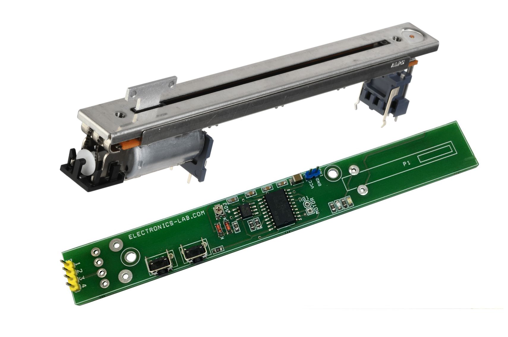
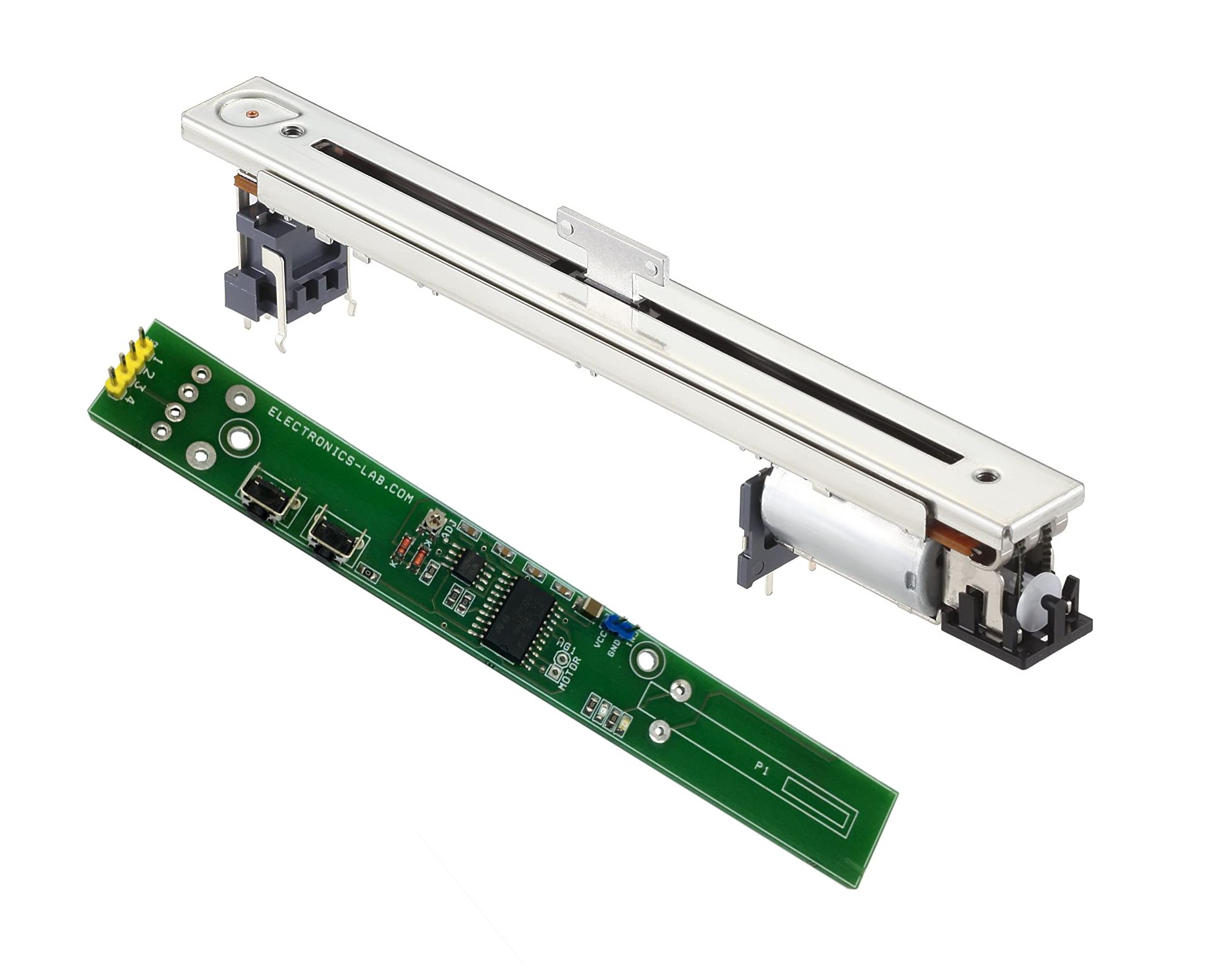
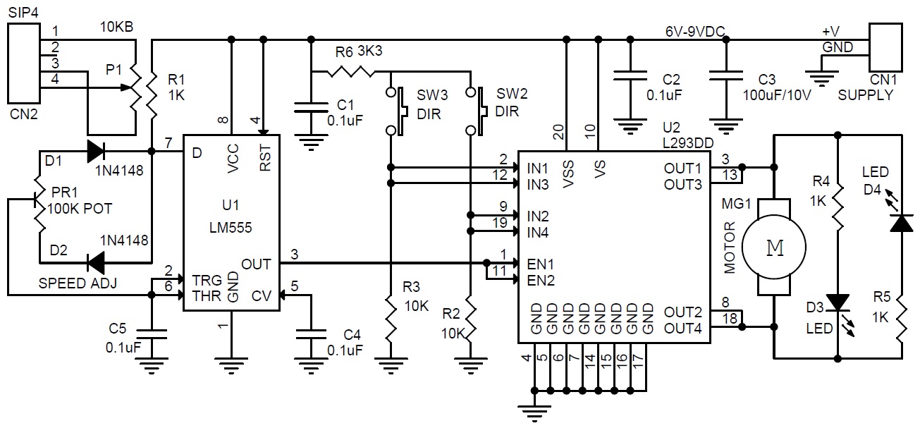
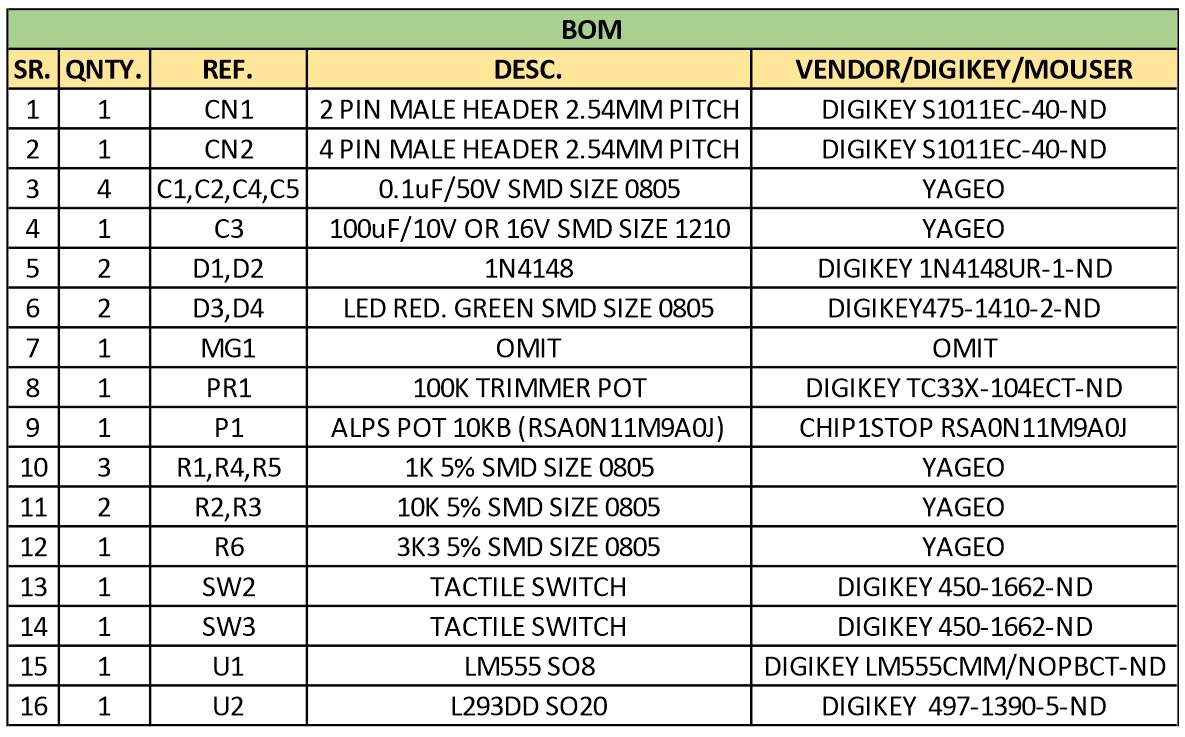
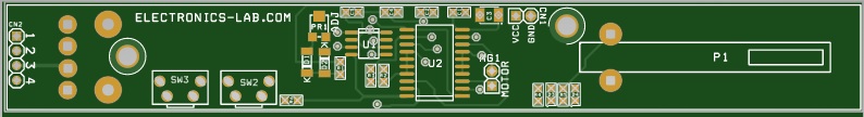
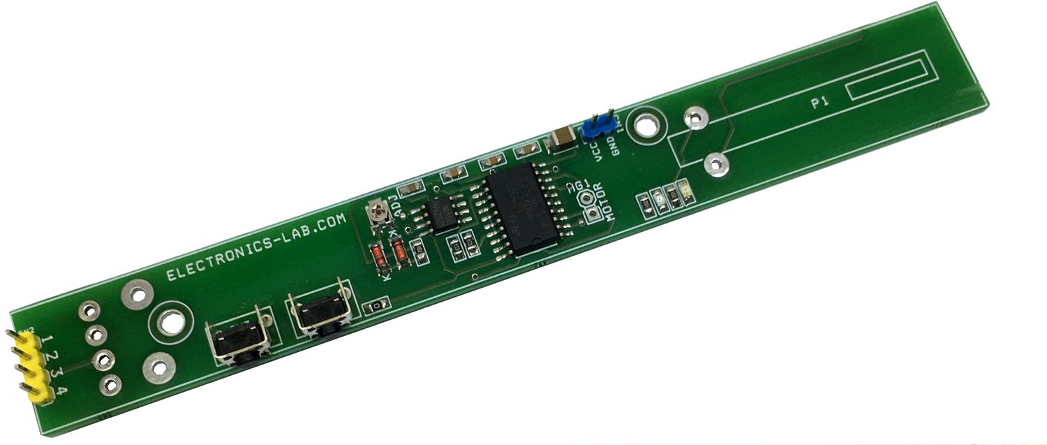
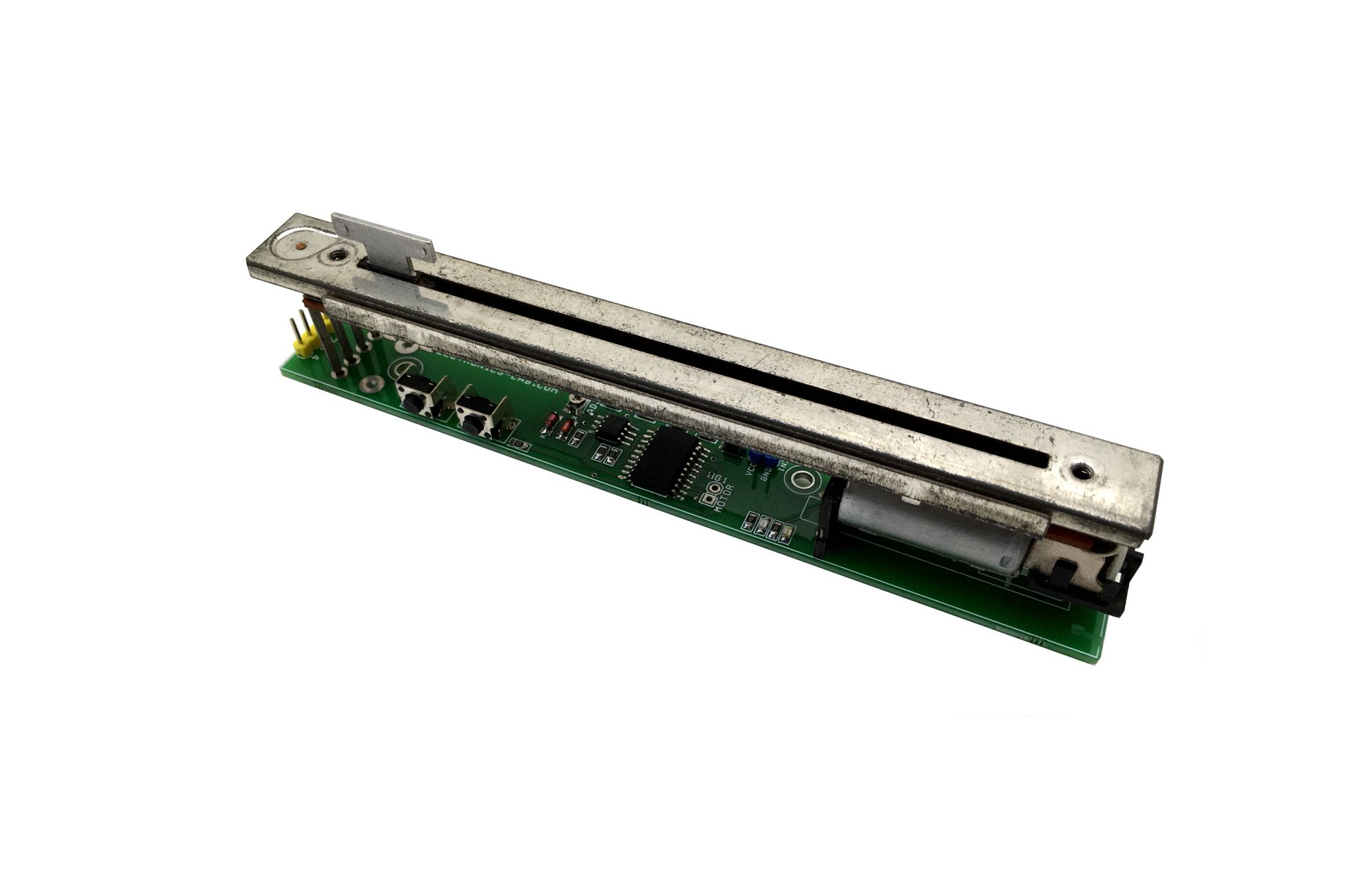
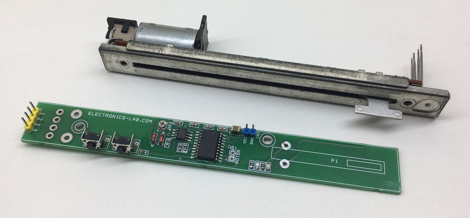
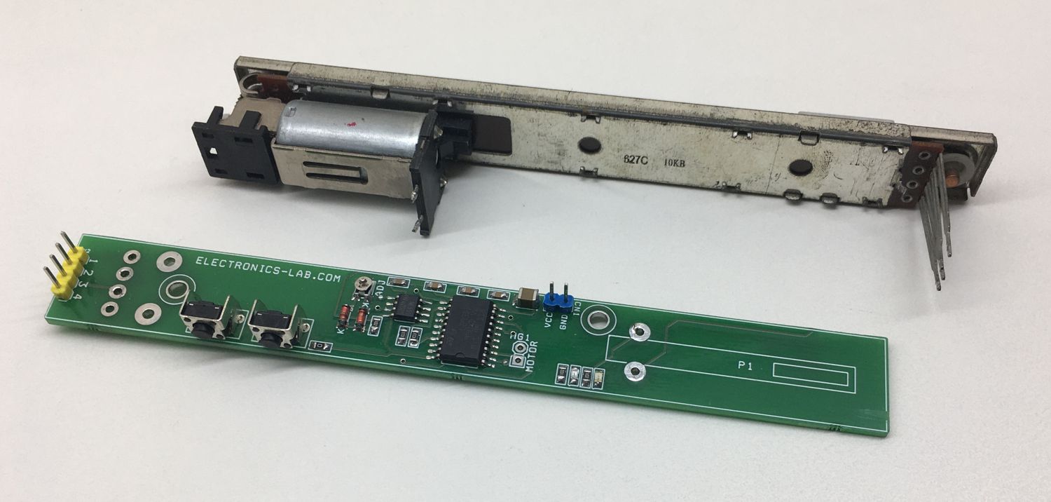
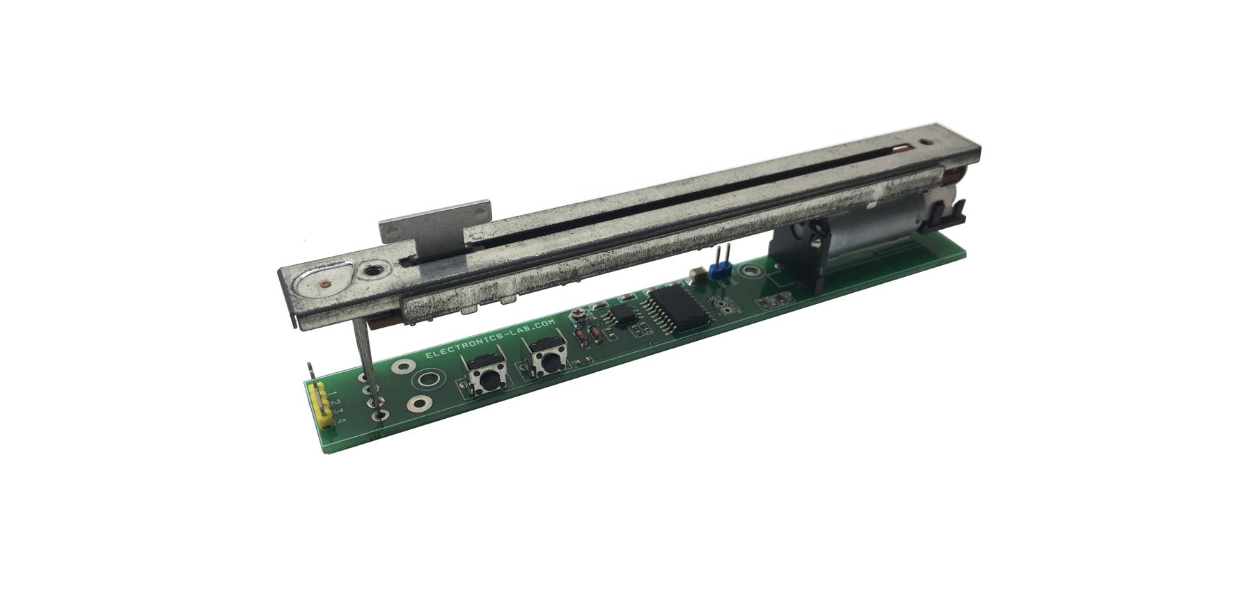
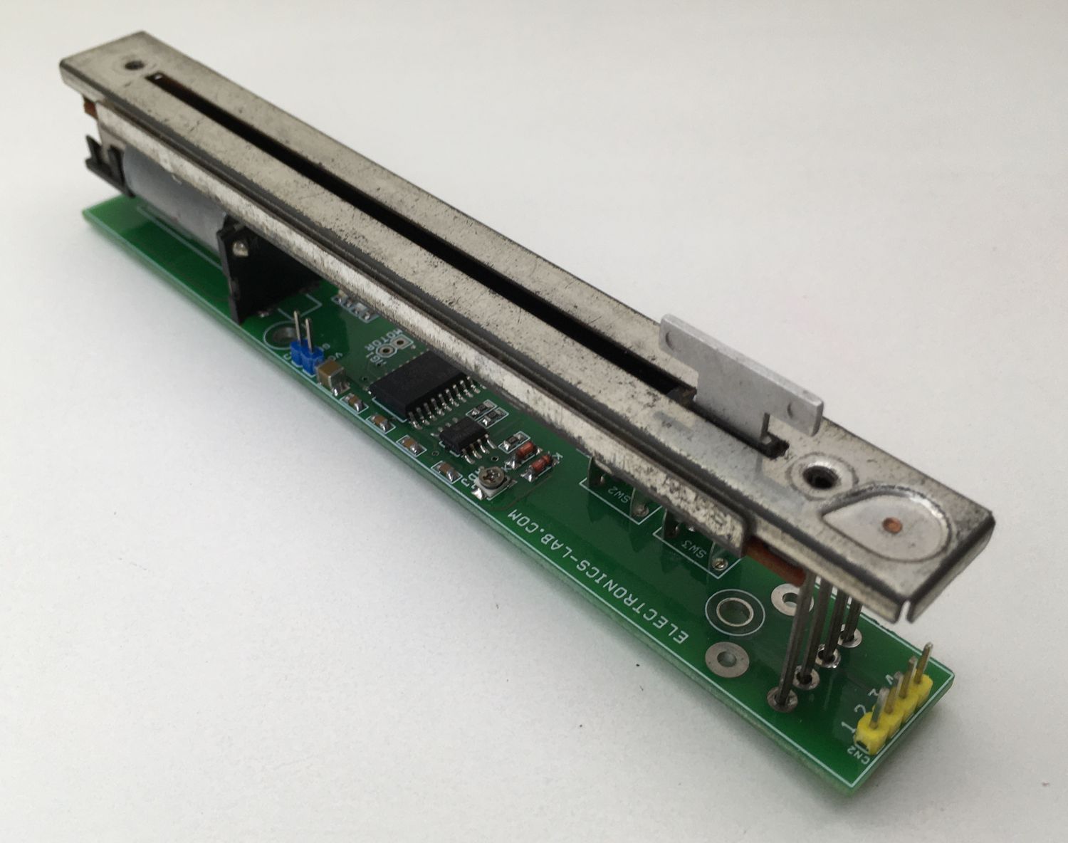
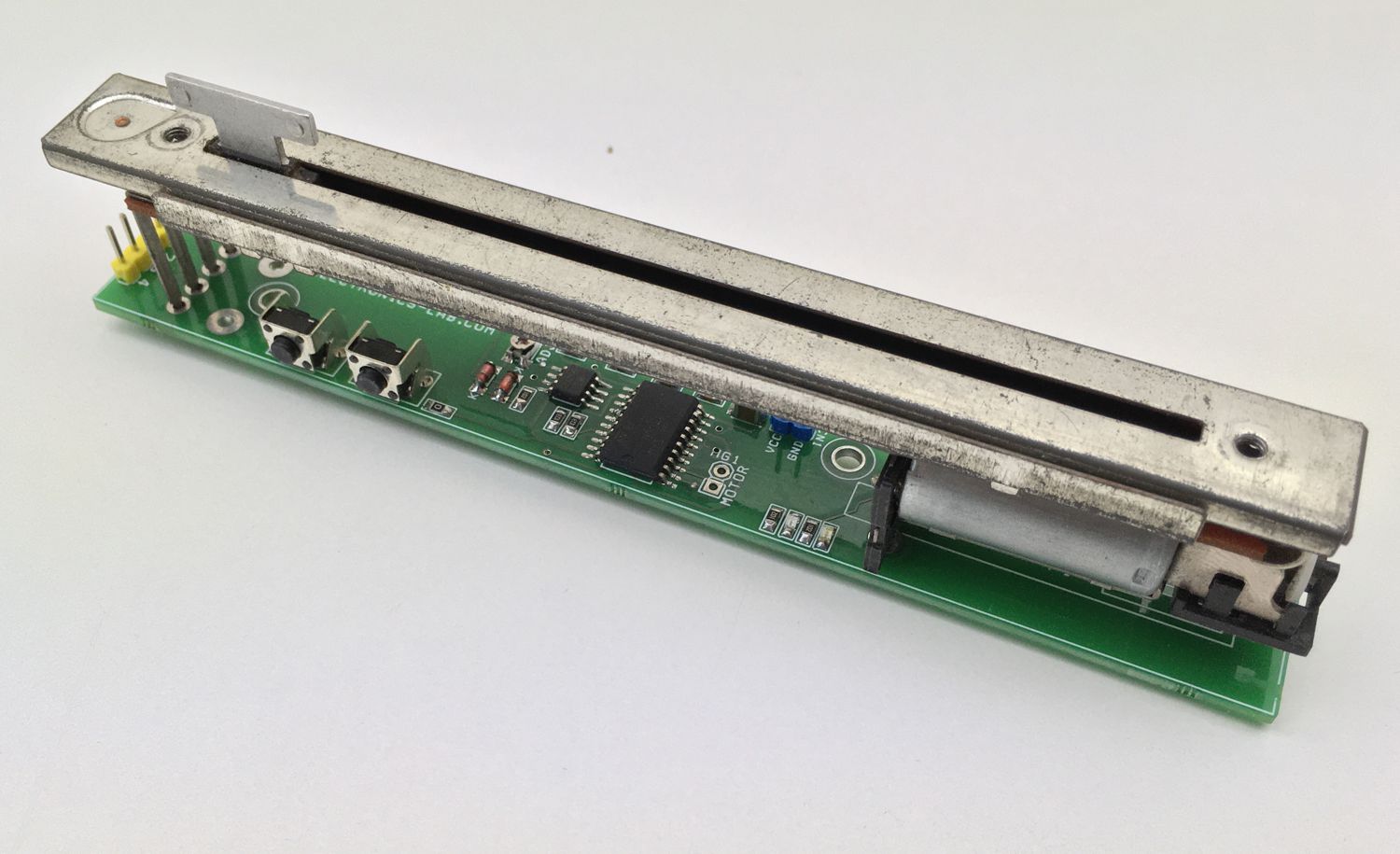
This motorized slide potentiometer is used in lighting and Audio/Video equipment or other similar application. It is a simple solution to control a motorized slide potentiometer using two tactile switches or a microcontroller interface. The project includes bidirectional motor driver L293DD H-Bridge chip, LM555 timer IC to generate the PWM pulse for speed control and two tactile switches to control the direction of the motor. Instead of two tactile switches, these pins can be interfaced with Arduino or microcontroller. SW2 and SW3 are used for CCW/CW motor control. PR1 trimmer potentiometer is provided to set the motor speed. Operating power supply of the project 6V to 9V DC. LED D3 and D4 Motor direction indicator. We have used a 10KB taper resistance potentiometer with a 100mm travel distance.
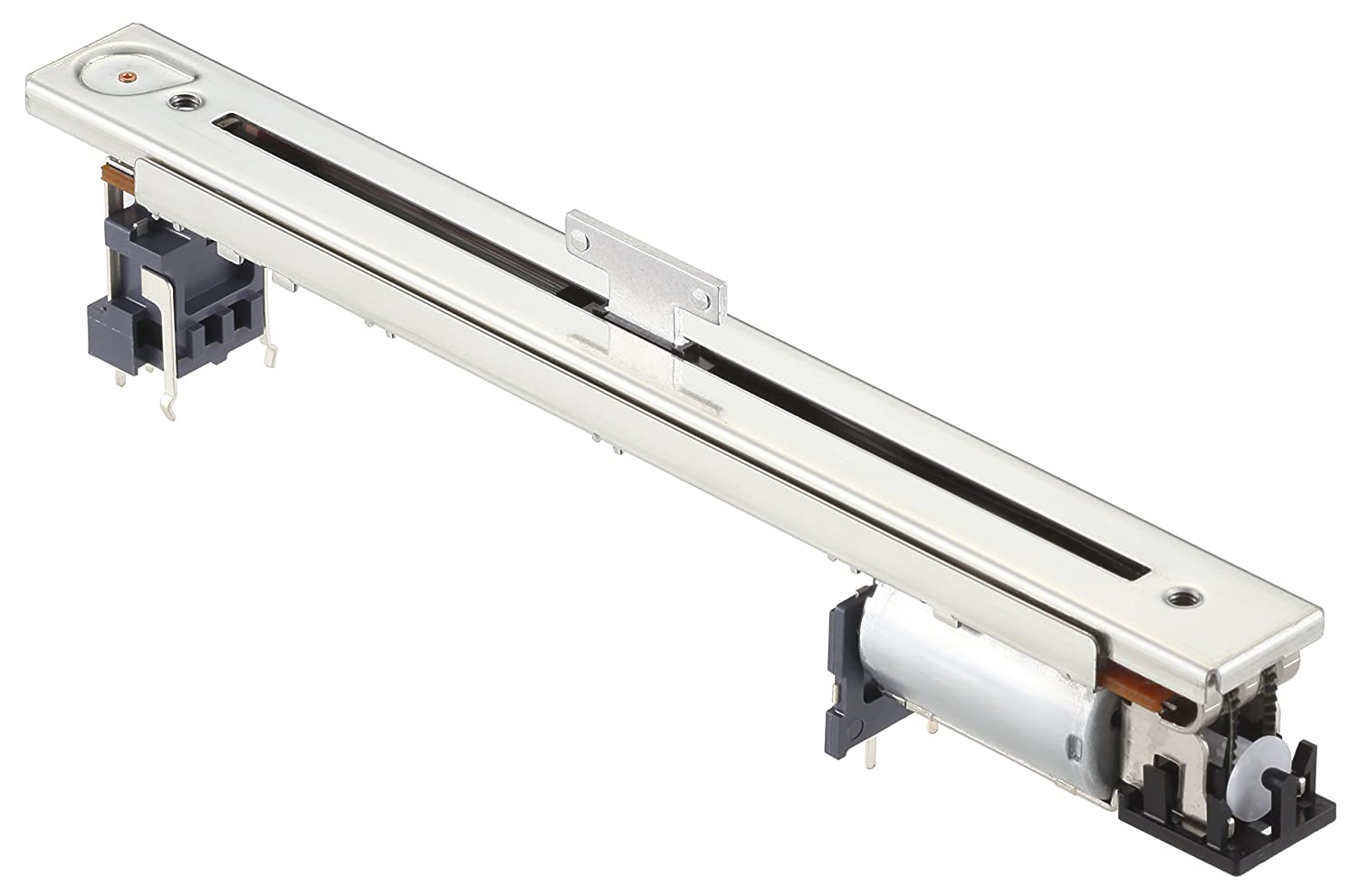
A motorized potentiometer is a slide pot which is has a timing belt driven by a small DC brushed motor and two-timing pulley. It is a single channel 10K Ohms B type resistance taper Pot.
Motor Slide Potentiometer (ALPS ALPLINE) – Part number: RSA0N11M9A0J
Features
Operating Supply 9V DC (6V to 9V)
Current consumption 400mA Peak
PWM Frequency Approx. 5Khz
Duty Cycle 10 to 90%
Motor Potentiometer Travel 100MM
Potentiometer 10K Resistance B Type Taper (RSA0N11M9A0J)
2 X Motor Direction LED
Trimmer Potentiometer for Motor speed adjust
2 X Tactile Switches Motor CW/CCW Direction Control
This tutorial will focus on a configuration commonly known as the multivibrator and particularly on op-amps based circuits. Indeed, multivibrators can also be designed thanks to bipolar transistors or also timer integrated circuits such as NE555 but we will focus on OPAMP implementation.
In its general definition, a multivibrator is an electronic oscillator that generates a non-sinusoidal waveform at its output such as a square or triangular signal for example.
Multivibrators can be differentiated into three categories depending on how they are controlled (the trigger):
Astable: no triggering
Monostable: one trigger pulse
Bistable: two trigger pulses
First of all, we focus on an op-amp based circuit known as the Schmitt Trigger, already briefly presented in the op-amp comparator tutorial. This circuit will indeed enable us to understand the major ideas behind the astable multivibrator.
In the following sections, we focus on the astable, monostable, and bistable op-amp based multivibrator circuits, their properties, and their differences.
Schmitt trigger
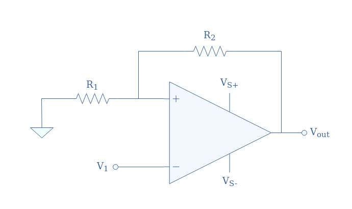
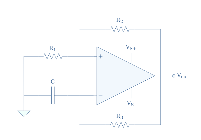
An inverting Schmitt trigger circuit is presented in Figure 1:
fig 1: Schmitt trigger circuit representation
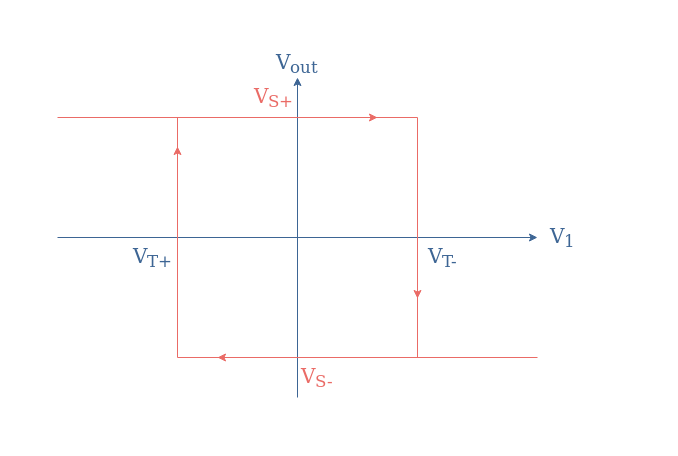
The transfer characteristic of this circuit is a hysteresis plot given by the following Figure 2:
fig 2: Transfer characteristic of the inverting Schmitt trigger
The threshold voltages are always symmetrical (VT-=-VT+) and given by:
VT+=-VS(R1/(R1+R2))=-βVS
VT-=+VS(R1/(R1+R2))=+βVS
With β=R1/(R1+R2) known as the feedback fraction provided by the voltage divider circuit. The supplying voltages VS+ and VS- can be assimilated to the saturation voltages of the op-amp.
As we can see from Figure 2, if the input signal V1 reaches or exceeds the threshold voltage VT-, the output will negatively saturate. After that, if the input decreases down to the threshold voltage VT+, the output will switch to its positive saturation level.
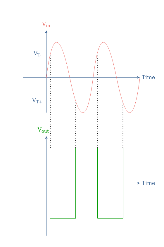
As a consequence, for any periodic signal input that is applied to the inverting pin of the op-amp, a rectangular output will be provided by the Schmitt trigger acting as a rectangular converter.
We show in Figure 3 how a sinusoidal waveform would be converted by the Schmitt trigger:
fig 3: Sinusoidal to rectangular signal conversion
It is interesting to note that the period of the output and input signals match, regardless of the position of the threshold voltages as long the amplitude of the input signal is higher than the threshold value.
Op-amp Astable Multivibrator
An op-amp based astable multivibrator circuit is presented in Figure 4:
As mentioned in the introduction section, we can see that in this example of an astable multivibrator, no external input signal is present as both inverting and non-inverting pins are indirectly wired to the ground. Instead, as we will detail during this section, the triggering signal will be provided by the charge/discharge cycles of the capacitor present at the inverting input.
The functioning of the astable multivibrator is quite simple, as when V+>V–, the output saturates in positive values and when V+<V–, the output saturates in negative values.
If we set an origin of time where the capacitor is fully discharged, the inequality V+>V– is respected and as long as this condition is valid, the capacitor is charged through the resistor R3. After a certain time, the charge of the capacitor is high enough so that the voltage produced across it exceeds V+, we obtain therefore the inequality V+<V–. Finally, the capacitor begins to discharge until the first inequality is satisfied again, the circuit will continue to oscillate permanently between these two states, thus the label “astable”.
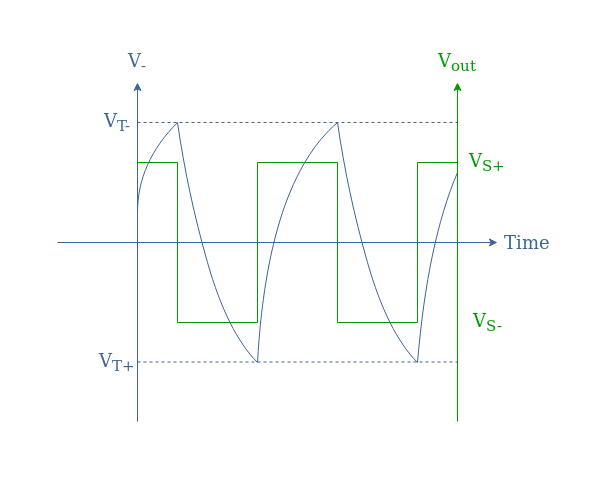
To illustrate this behavior, a chronogram of V– (the capacitor voltage) and Vout is presented in Figure 5:
fig 5: Input/output chronogram of the astable multivibrator
The sawtooth shape for the voltage V– is typical for a capacitor that charges and discharges by following laws of the form:
V–(t)=VT(1-exp(-t/τ)) for the charge
V–(t)=VTexp(-t/τ)) for the discharge
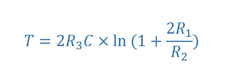
With τ being the time constant equals to the product R3×C. It can be demonstrated that the period T for the output signal can be expressed such as:
eq 1: Output period expression for the astable multivibrator
Therefore, we can see that by increasing either the value of R3 or C, the time constant τ is increased, which increases the charge and discharge time of the capacitor and in turn decreases the frequency of the output signal. Moreover, the period can be modified by changing the values of the feedback resistor (R2) and the resistor at the non-inverting input (R1).
Op-amp Monostable Multivibrator
The monostable multivibrator possesses one stable state and one unstable state that can be triggered by an external signal, the period of the unstable state depends mostly on an RC circuit but also on the command.
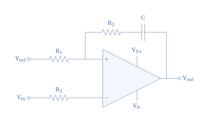
We present in Figure 6 an op-amp based monostable multivibrator:
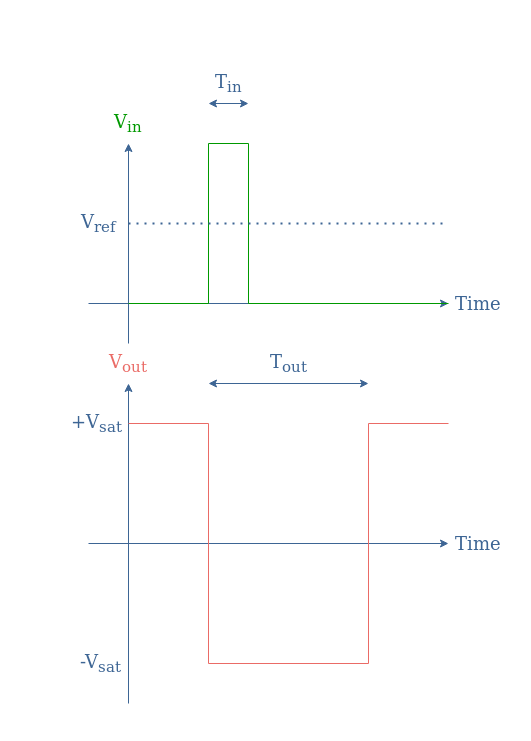
We can already note that this circuit is an inverting comparator as the input is applied to the inverting pin and compared to the reference provided to the non-inverting pin. If Vin<Vref (resp. Vin>Vref), we obtain Vout=Vsat (resp. Vout=-Vsat).
When Vin<Vref, the op-amp saturates in positive values, the voltage across the capacitor (which is fully charged) can therefore be expressed by the difference Vsat-Vref. This state is stable as long as the condition Vin<Vref is satisfied.
In order to induce a change of state for a certain period Tout, the input signal Vin must increase and be higher than the reference value Vref. This can be achieved with an impulsion of period Tin provided to the inverting input such as shown in Figure 7:
fig 7: Input/output chronogram of the monostable multivibrator
The period Tout for which the system is unstable corresponds to the time constant of the capacitor discharge given by the product R2×C.
Op-amp Bistable Multivibrator
At the last type of multivibrator, the bistable configuration, both states are stable and the transition from one to another requires a different type of trigger.
The circuit of a bistable multivibrator is actually the same as an inverting Schmitt trigger which is already presented in Figure 1.
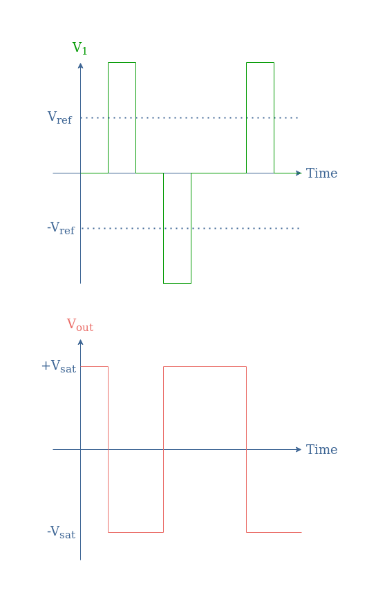
Before detailing the function of this circuit, we present its corresponding chronogram where we show how the transition between states is triggered:
As we can see, the transition from the +Vsat to -Vsat is realized similarly than for the monostable configuration by a positive impulse at the inverting input. The transition back from -Vsat to +Vsat is however not spontaneous as both states are here stable, it requires therefore a negative impulse.
In order for the impulses to effectively trigger the state transition, their absolute value must be higher than a certain reference value (Vref) given by the voltage absolute value at the non-inverting pin βVsat.
To understand the function, we can describe how the circuit behaves depending on the input signal provided:
Before the first input impulse, V1=0 and V+=βVsat, since V+>V1, Vout=+Vsat. When the first positive impulse input is applied, V1>V+ and therefore the output and non-inverting voltage switch both to a low state, respectively Vout=-Vsat and V+=-βVsat. When V1=0 again after the end of the first impulse, the output signal remains at -Vsat because V1>V+. In order to transition back to the initial state, V1 must become lower than V+ which is achieved by a negative impulse of absolute value greater than βVsat.
Conclusion
Multivibrators are simple electronic oscillators that can be used for logical applications (with two states) such as timers or flip-flops. They can be implemented thanks to operationnal amplifiers, and particularly with a comparator-based configuration.
The first section of this tutorial is a reminder for the Schmitt trigger configuration which constitutes the base design for the multivibrators presented in this article. A Schmitt trigger is a simple comparator circuit which output can only be equal to two distinct values and which depends on whether the input provided is higher or lower than a certain reference voltage.
The astable multivibrator is a Schmitt trigger which input branch is a feedback loop with an additional RC series component. No external input is present in this circuit as the discharge/charge cycles of the capacitor provides the necessary trigger signal in order for the output to permanently switch between its high and low states.
For the monostable multivibrator, the reactive component is present in the positive feedback loop of the Schmitt trigger. This particular desgin ensures that one state is stable and the other is unstable as the circuit always tends to come back to its initial state. In our example, the transition from a high to a low level is triggered by an external positive impulse, the period of this unstable state is given by the time constant of the RC series branch.
Finally, the bistable multivibrator is the most basic circuit as it is exactly the same design as a Schmitt trigger. In this case, both low and high states are stable and the transitions are triggered by either positive or negative impulses.
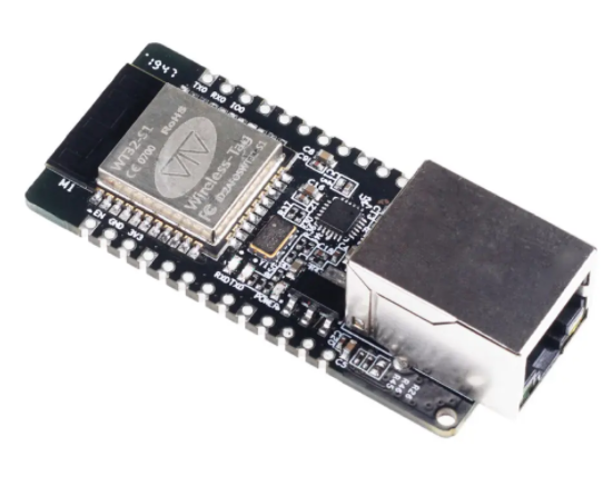
We have seen how good the ESP32 series of microcontrollers is, as they are probably the second favorite (only dethroned by the mighty Arduino boards) among makers, with their connectivity being their strongest suit, making it easy to develop IoT applications with Wi-Fi and Bluetooth capabilities. Besides that, you get a low power board with lots of peripheral options and online support, you cannot really go wrong with it. Now, the new WT32-ETH01 builds upon what already good there is about the ESP boards and adds something to the mix!
The WT32-ETH01 is a new development board that revolves around the ESP32 SoC. For those who are not familiar, you get a dual-core processor, 32MB of Flash memory, and onboard Wi-Fi (wit multiple modes, security options, encryptions, and protocols that cover the entire OSI model) and Bluetooth 4.2, along with other important peripherals that you expect for your projects, such as UART, SPI, SDIO, PWM, I2S, ADC, DAC, among others. Besides that, you get a temperature and a hall sensor. All this, of course, in a small form factor and featuring multiple low power modes.
The first thing that hits the eye is the Ethernet connectivity, powered by the LAN8720A transceiver, that does not support Power over Ethernet. As you may know, this is not the first ESP32-based board with it, so, what makes it so special? Well, the price is $5.90, which is cheap even for an ESP32 board. Besides that, its breadboard-friendly packaging makes it easy for you to develop new projects. You will notice that there is no USB on the board, so, to program it, you will need a USB to TTL boards, which is unfortunate but you probably have one laying around anyway. More unfortunate is having to power it up from an outside source.
Another ESP32 ready to size-down your home automation ideas
Regarding firmware, it ships with a program that can be controlled via AT commands, but you can easily change that, as you can on every ESP32, and run Arduino code or MicroPython. You can also use the Tasmota firmware, an open-source firmware that makes it easy to develop home automation solutions.
Lastly, where can you apply it? That is easy. With a price like that and such a small form factor, a feature-packed board at this price, with great software support makes for an ideal candidate as your go-to board for your projects. When it comes to the rest, its connectivity makes anything house related a breeze, as you can connect your phone via Bluetooth, connect it to your home Wi-Fi and let your creativity take place. You can even take advantage of the low power features to make something battery powered.
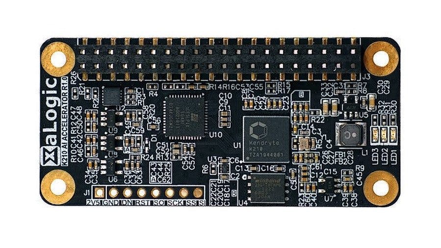
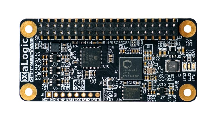
Shortly after XaLogic unveiled the XAPIZ3500 HAT intended to bring deep learning to the Raspberry Pi Zero, the Asian – based company who is consistently committed to enabling machine learning capabilities at the edge, has again unveiled a new K210 AI Accelerator that looks to bring Kendryte K210-powered AI Acceleration to the Raspberry Pi. The Kendryte K210 system-on-chip so far has proven popular for edge AI tasks and XaLogic is looking to bring the technology to the Raspberry Pi family of single-board computers using a simple add-on HAT.
The redesigned HAT allows fast development of real-time machine learning applications at the edge.
“K210 AI Accelerator is a Raspberry PI HAT powered by the Kendryte K210 AI Processor,”
says XaLogic, concerning their design.
“It fits into any [Raspberry Pi] with a standard 40 pins connector and gives it a Neural Engine Accelerator (Kendryte K210) with 0.5 TOPs (Tera Operations) processing power. Using one of our many free pre-trained models, you can add machine vision features using deep learning in a matter of minutes. So you can add AI features to your [Raspberry Pi] based camera even if you don’t know how to train your model.”
Features of the K210 AI Accelerator:
It adheres to the Hardware Attached on Top (HAT) standard
It has a very compact solution as it has the same footprint as the compact Raspberry Pi Zero family of single-board computers
Comes with lots of pre-trained models for developing smart AI applications without having to go through the tedious flow of training your neural networks, and,
Few APIs in Python give cool features such as real-time face detection, object detection etc.
The K210 AI Accelerator is also expected to come with open source software, sample Caffe and TensorFlow projects to help users create their own custom neural network, as well as a secured communication for fast IoT deployment.
“Once you are ready to deploy your edge devices, secure it easily when connecting to Amazon Web Services by leveraging on the Infineon Trust-M security chipset on the K210 AI Accelerator.”
More details on the K210 AI Accelerator including schematics, source codes and get started demo can also be found on the company’s website or their Crowd Supply page.
The crowdfunding campaign for the board is yet to be launched, but you can sign up and get the chance to receive updates and be notified when it finally does.
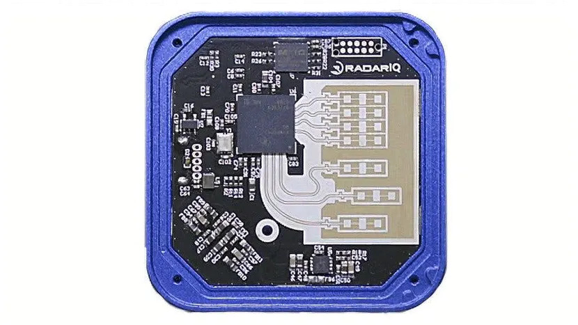
With the mindset of making millimeter RADAR (mmRadar) easily available and affordable to makers, tinkerers, and engineers around the globe, RadarIQ has launched a crowdfunding campaign for their new RadarIQ-M1 Sensor on Kickstarter. It is an attempt to make Radar technology open to every enthusiast. The RadarIQ sensors are designed to be affordable, and very easy to use. As claimed by the company, it can be integrated and run in a project in under 15 minutes.
The RadarIQ sensor is an affordable mmWave radar sensor designed for robotics and industrial applications. Data processing from the sensor is processed bundled software, compatible with Windows, macOS, and Linux operating systems. RadarIQ-M1 Sensor uses frequency-modulated continuous-wave (FMCW) radar in the 60-64GHz spectrum. It is limited to a 10m range as of now. The company claims high accuracy for close-up tasks, with a 110 degree horizontal and 15-degree field of view and up-to-30 frames per second refresh rate.
It can accurately detect distance, speed, and orientation for multiple objects. The company claims the modules are compatible with everything from ROS-based robots and Raspberry Pi single-board computers. It can integrate with low-power Arduino microcontrollers via USB and TTL UART buses.
Key Specs of the RadarIQ:
Range: 0-10m
Frequency: 60-64GHz
Horizontal field of view: 110 degrees
Vertical field of view: 15 degrees
Frame rate: 1-30 frames per second
Speed range: 0-3m/s
The minimum distance between objects: 40mm
Power consumption: 5V 0.38A (0.48 peak)
Communications:
Virtual COM port over USB
TTL UART
Key Features & Applications:
Detect moving objects easily.
Accurately measure speed.
Accurately measure distance.
Can see through walls and can therefore be installed inside an enclosure.
Impervious to low visibility environments such as fog or smoke.
Obstacle/obstruction detection
Object detection
Object tracking
Speed measurement
Distance measurement
Fusion with vision sensors
Supported platforms:
Arduino (Arduino requires external power supply)
Raspberry Pi
Linux
Windows
MacOS
Important notes:
The 60-64GHz frequency range is not permitted for use in automotive applications.
The sensor must be used at distances greater than 20cm away from a human body.
The modules are available to fund on Kickstarter, ahead of an estimated April 2021 delivery date, priced at NZ$320 (around $211) each.
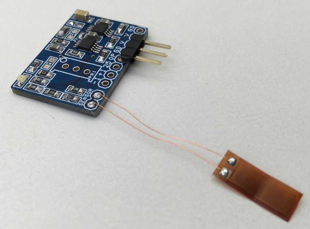
This is a new project, a single supply instrumentation amplifier with onboard bridge configuration, and a 2.5V precision reference voltage chip. The project can be configured for applications such as thermocouple amplifier, bridge amplifier, ECG amplifier, pressure sensors, medical instrumentation, portable instrumentation, RTD sensor amplifier. The project is based on INA333 micropower, zero drift, rail to rail out instrumentation amplifier chip. REF5025AID chip provides a precise 2.5V reference voltage. The board can be configured as an instrumentation amplifier or as a strain gauge amplifier with few easy changes.
Strain Gauge Sensor Amplifier OR Single Supply Instrumentation Amplifier – [Link]
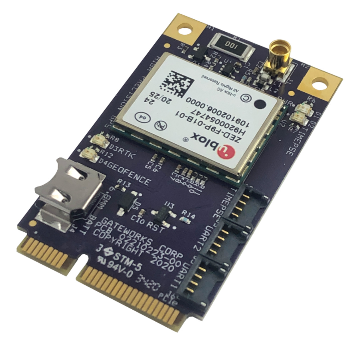
Gateworks is pleased to release a new high precision GNSS / GPS Mini-PCIe adapter based upon the u-blox ZED-F9P. The GW16143 enables precision navigation and automation of moving machinery in industrial applications such as agriculture, mining, and field mapping. Differential GNSS devices such as the GW16143 are starting to replace survey-grade equipment where precision is important. Multi-band Real-time kinematic (RTK) technology provides fast convergence times and reliable performance. The module supports both base and rover operation for RTK applications. Other radio cards such as the Gateworks GW16130 Iridium Satellite Modem or GW16132 CAT-M1 modem can provide communication links for the augmentation data.
GW16143 High Precision Mini-PCIe Card Highlights:
High Precision u-blox ZED-F9P GNSS/GPS Mini-PCIe Adapter
Concurrent reception of GPS, GLONASS, Galileo and BeiDou
Centimeter-level (<2cm) Accuracy GNSS positioning
Integrated Multi-Band Real Time Kinematics (RTK)
High update rate for highly dynamic applications
Allows for RTK “Base” and “Rover” Operation
Two UART headers for correction data over serial, PPS timepulse output header
Uses Standard NMEA, UBX and RTCM Message Format
Uses Mini-PCIe USB Signaling
Status LEDs
Rechargeable Lithium battery, 3.3V, 3mAH, 6.8mm
RTCM 3.x, SSR, SBAS Corrections
<1.0m SBAS, <0.2m SSR, <0.03m RTCM 3.x
Supports L1 and L2/L5 Bands
Rugged & Industrial design
-40C to +85C Industrial Operating Temperature
Made in the USA
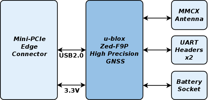
A MMCX antenna port allows for an external antenna. USB signaling is used on the Mini-PCIe connector to communicate with the host processor. Two UART headers are available to allow for correction data over serial. A PPS timepulse output header is also available. For faster cold start acquisition times, a rechargeable 3.3V lithium battery is provided.
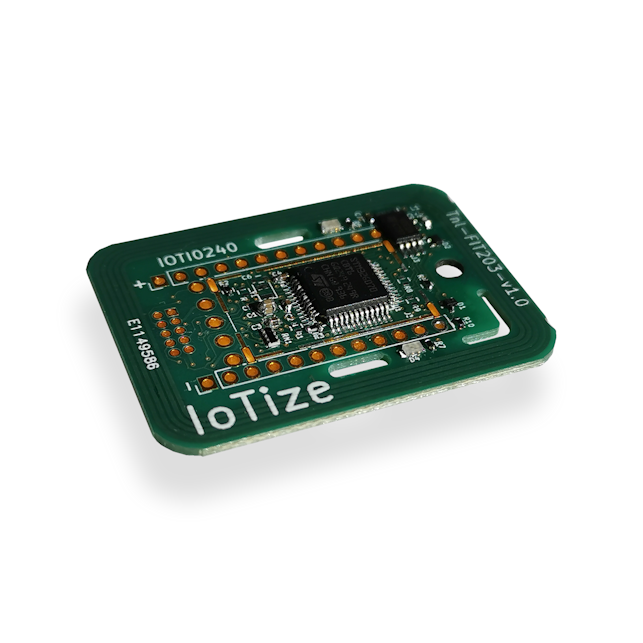
IoTize’s NFC module allows designers to add NFC 3-stroke configuration rapidly and with virtually no expertise
IoTize’s TapNLink TnL-FIT203 enhances user experiences with NFC 3-stroke configuration, providing an easy and secure way of viewing and updating appliance parameters using iOS or Android mobile phones. With NFC 3-Stroke configuration, users update parameters of appliances or machines in three steps:
approach the phone to the appliance to connect and read the actual configuration
view and modify settings in the mobile app
approach the phone to the appliance again to send the new parameters
With NFC, connecting mobile phones to appliances is automatic, intuitive, and secure. There are no addresses or codes to enter; just place the phone within a couple of inches of the NFC indicator on the appliance. The connection is established, data is read, and the appropriate app is launched instantaneously. Appliance users view and modify settings more easily with their mobile phones than with an on-board LCD-based user interface. Settings can even be stored and recalled for later use.
With TapNLink TnL-FIT203 appliance and equipment designers can add NFC 3-stroke configuration rapidly and with virtually no expertise. Designers simply connect TapNLink to their electronic design and configure it. The free IoTize Studio configuration software does the rest and automatically generates apps for iOS and Android mobile phones. No coding is required.
Features
Near field communication (NFC) Type5 tag (ISO/IEC 15693)
Configurable access profiles
Configurable, encrypted passwords
AES-128 data encryption
Configuration of up to 500 accessible data addresses
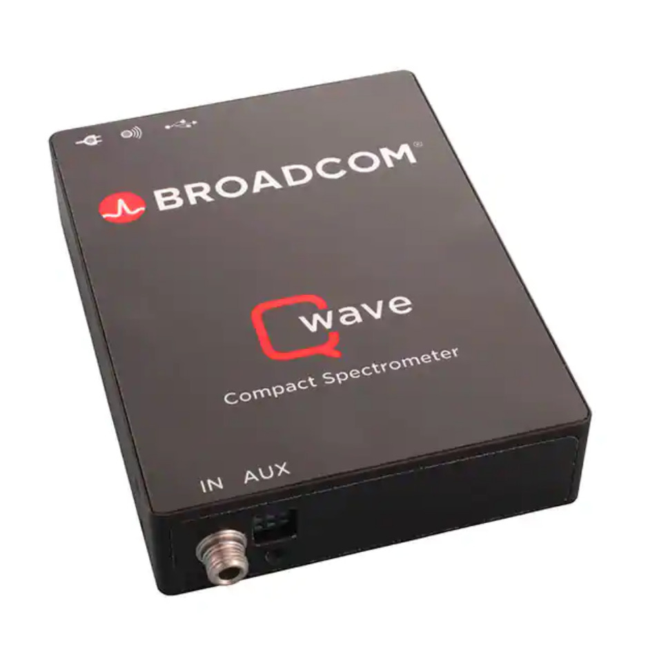
Qwave NIR–Compact USB spectrometer with high resolution and sensitivity for NIR measurements from 700 to 1030 nm
Armed with a high-resolution 3,648-pixel linear CCD detector, Broadcom’s Qwave 2 series can cope with bulkier spectrometer designs while maintaining a package size of 89.5 mm x 68.0 mm x 19.5 mm. Together with the smart spectrometer software Waves and various communication interfaces, the Qwave is the ideal spectroscopic instrument to be integrated into high-performance applications.
The TSZ181, TSZ182 are single and dual operational amplifiers featuring very low offset voltages with virtually zero drift versus temperature changes.
The TSZ181, TSZ182 are single and dual operational amplifiers featuring very low offset voltages with virtually zero drift versus temperature changes. They offer rail-to-rail input and output, excellent speed/power consumption ratio, and 3 MHz gain-bandwidth product, while consuming just 1 mA at 5 V. The device also features an ultra-low input bias current. These features make the TSZ18x ideal for high-accuracy high-bandwidth sensor interfaces.
Key features
Very high accuracy and stability
Rail-to-rail input and output
Low supply voltage: from 2.2 to 5 V
Low power consumption: 1 mA max. at 5 V
Additional features
Very high accuracy and stability:
Offset voltage 25 µV max. at 25 °C, 35 µV over the full temperature range (-40 to 125 °C)
Rail-to-rail input and output
Low supply voltage: 2.2 – 5.5 V
Low power consumption: 1 mA max. at 5 V
Gain bandwidth product: 3 MHz
Automotive qualification
Extended temperature range: -40 to 125 °C
Micro packages: DFN-8 2 x 2, SO-8 and MiniSO-8
Additional Benefits:
Higher accuracy without calibration
Accuracy virtually unaffected by temperature change