Printed circuit boards make the creation of electronic devices in a repeatable and reliable manner a possibility. However, due to factors such as long turnaround time, cost, and other challenges associated with making PCBs through established fab houses, electronics hobbyists and prototype engineers usually turn to DIY approaches of PCB development like the heat transfer method and the UV-based design transfer method. While the UV-based system with pre-sensitized PCBs is more reliable, the heat-based system is far more popular due to the complexity and cost of setting up the UV chamber required for a UV-based system. To remove these barriers and make the pre-sensitized PCB approach accessible to everyone, Youtube DIY Star; “Techbuilder“, recently shared the process of creating a DIY Digital PCB Exposure Box in a video.
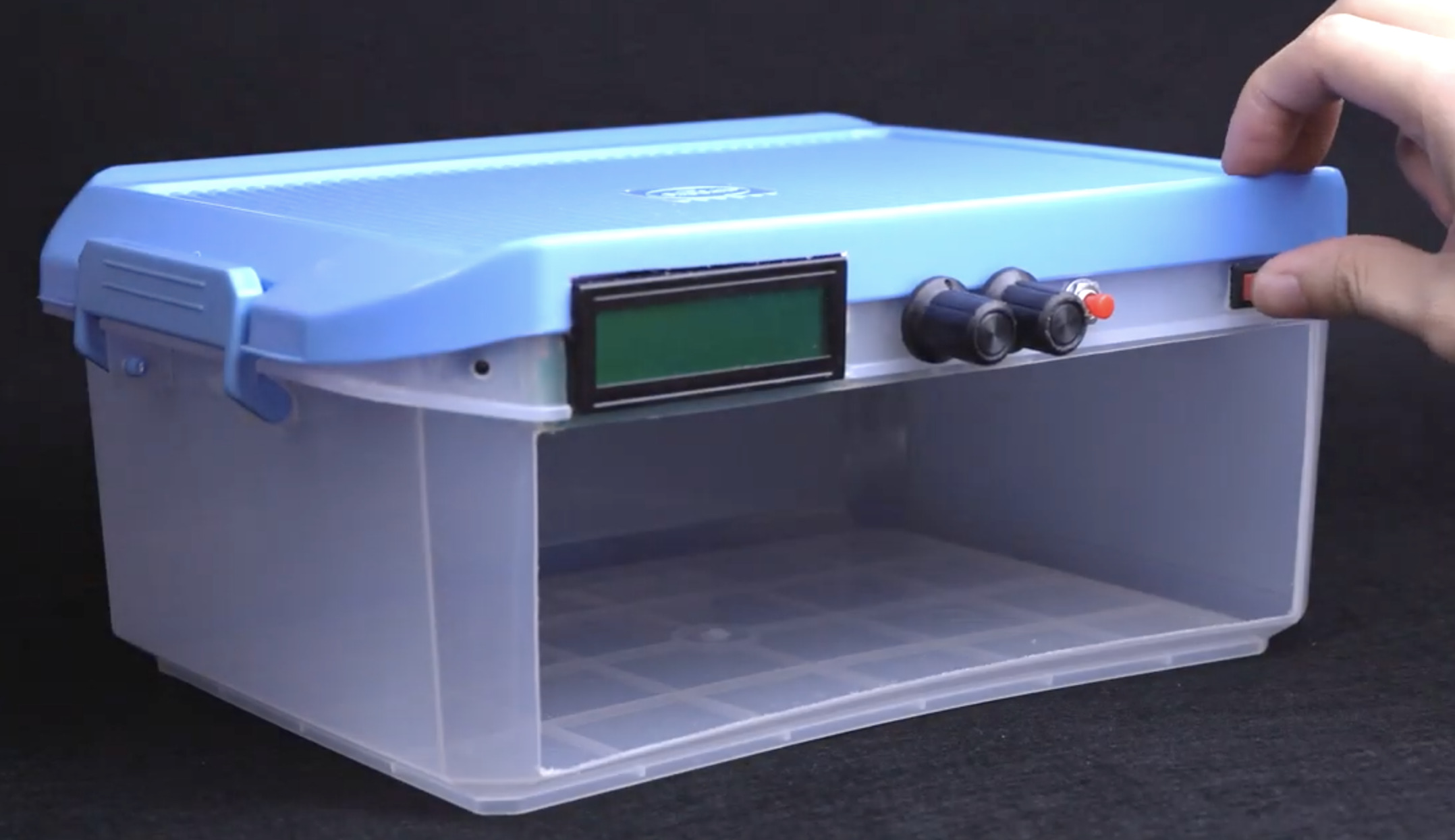
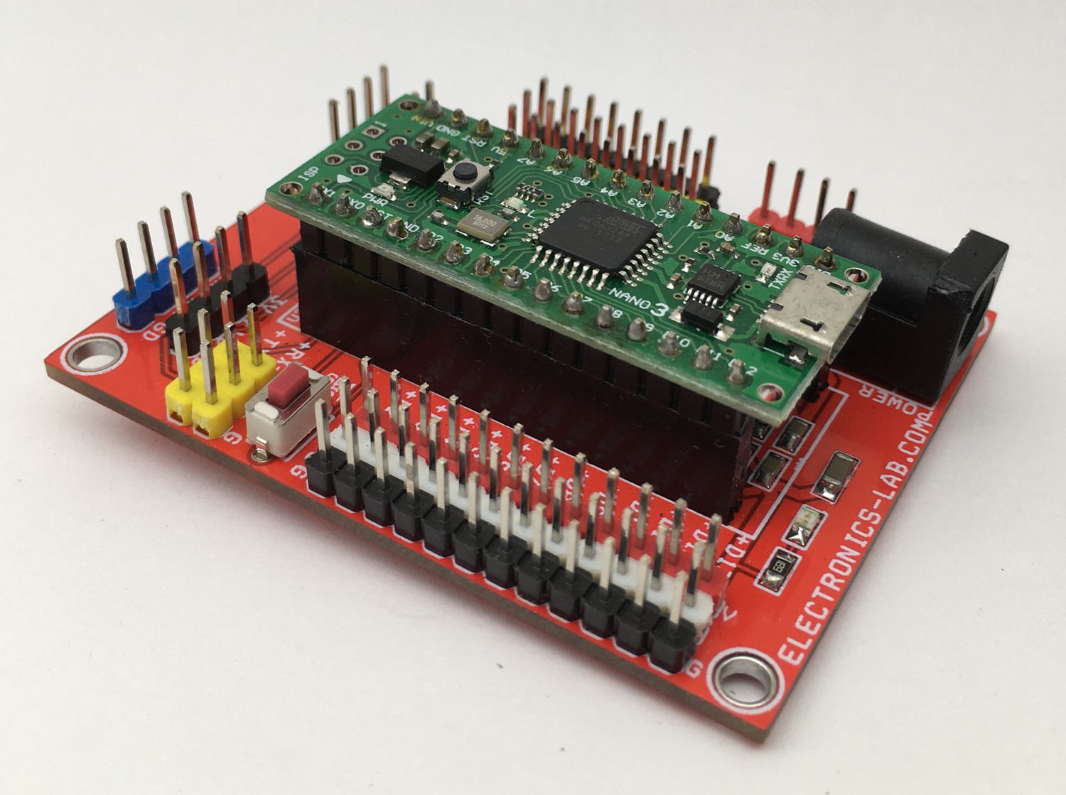
The Exposure Box which was made from a recycled components box, had it’s top lined with LED strips that are turned “on” or “off” by an Arduino Nano based control system. The control system makes use of time duration, preset by the user via a potentiometer, as the control variable. It turns off the light when the preset time has been attained, ensuring the PCB is not overexposed.
Today’s tutorial will lay out the project in a step-by-step manner to make it easy for you to replicate.
Ready? let’s go!
Required Components
To build the DIY Digital PCB Exposure Box, you will need the following components:
- Plastic Container
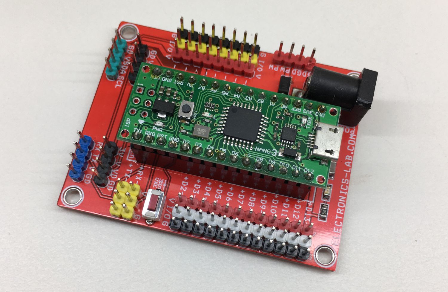
- Arduino Nano
- White LED Strips
- UV LED Strips [Better]
- 12V 2A Power Brick
- TIP31C NPN Transistor
- 10k Ohm Trimmer Resistor
- 10k Ohm Potentiometer
- 10k Ohm Resistor
- 470 Ohm Resistor
- 100 Ohm Resistor
- Male Headers
- Power Switch
- Piezo Buzzer
- DC Jack
- PCB Materials
While you may be able to salvage some of these components from old projects/a dumpster dive, the components can also be bought via the links attached to them. In case you are not able to get the exact components, the project is flexible and almost all of the components can be swapped with close alternatives. For instance, you can decide to use the cheaper and smaller Arduino Pro-Mini instead of the Arduino Nano.
Schematics
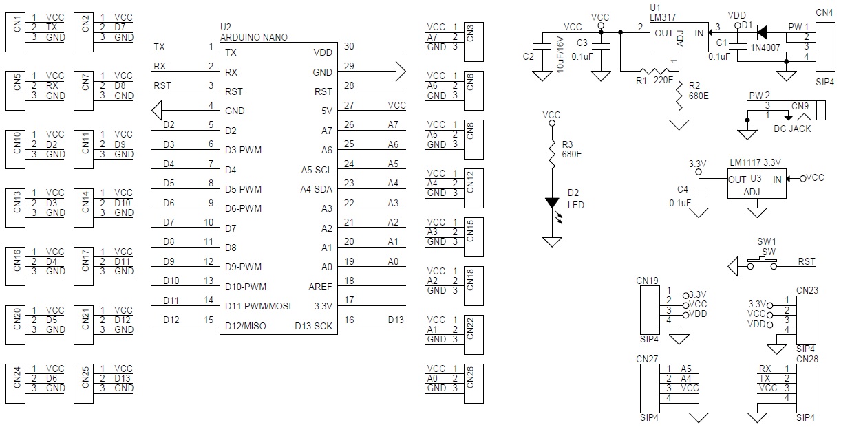
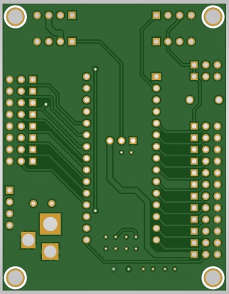
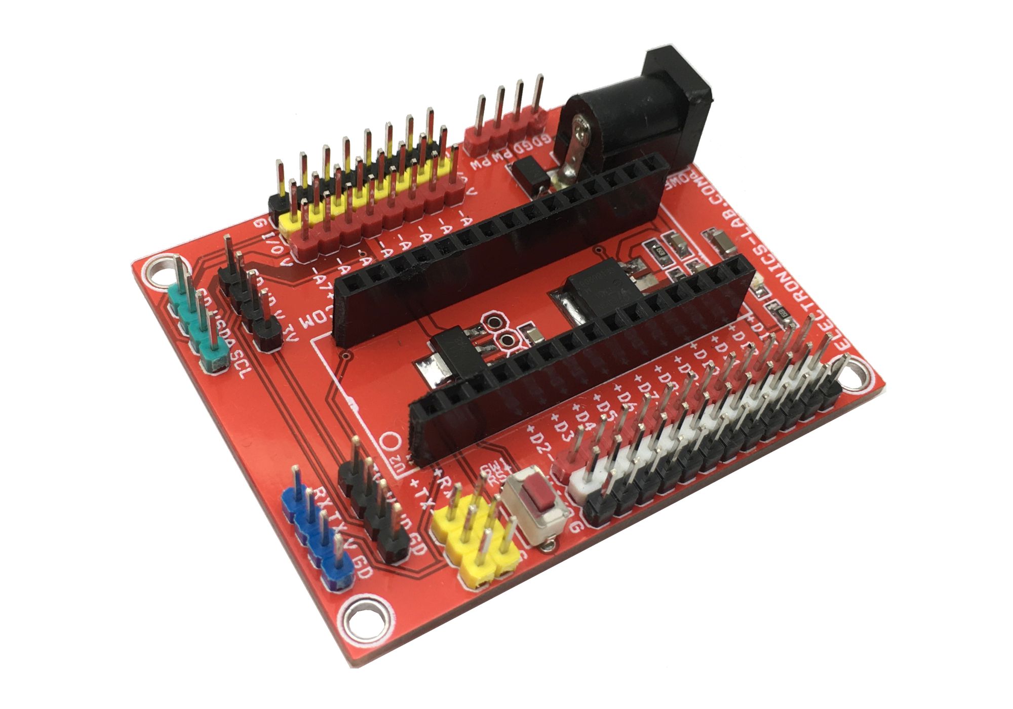
The schematics for the project is provided in the image below. The project was implemented on a PCB to make it more compact and easy to mount on the enclosure, but by carefully following the schematics below, you should be able to replicate the project on a veroboard or breadboard.
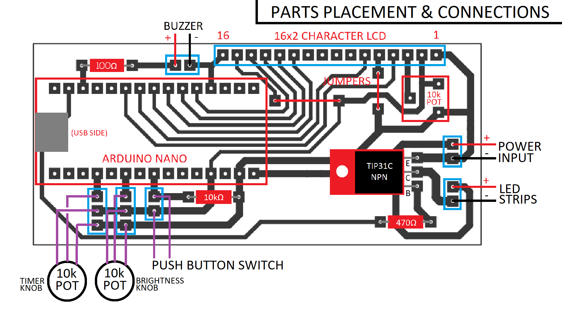
The schematics and PCB were created using Proteus and the project file with the schematics and PCB is attached under the download section to make it easy to replicate.
Project Enclosure and Assembly
The enclosure is an important part of this project and it makes sense that Techbuilder made use of components box, as they can be easily bought from any electronics component store. But just in case you are unable to get your hands on the exact kind of box, you can make do with any kind of box with a good opaque top. A wooden enclosure should also work great.
With the enclosure secured, follow the steps below to put it together.
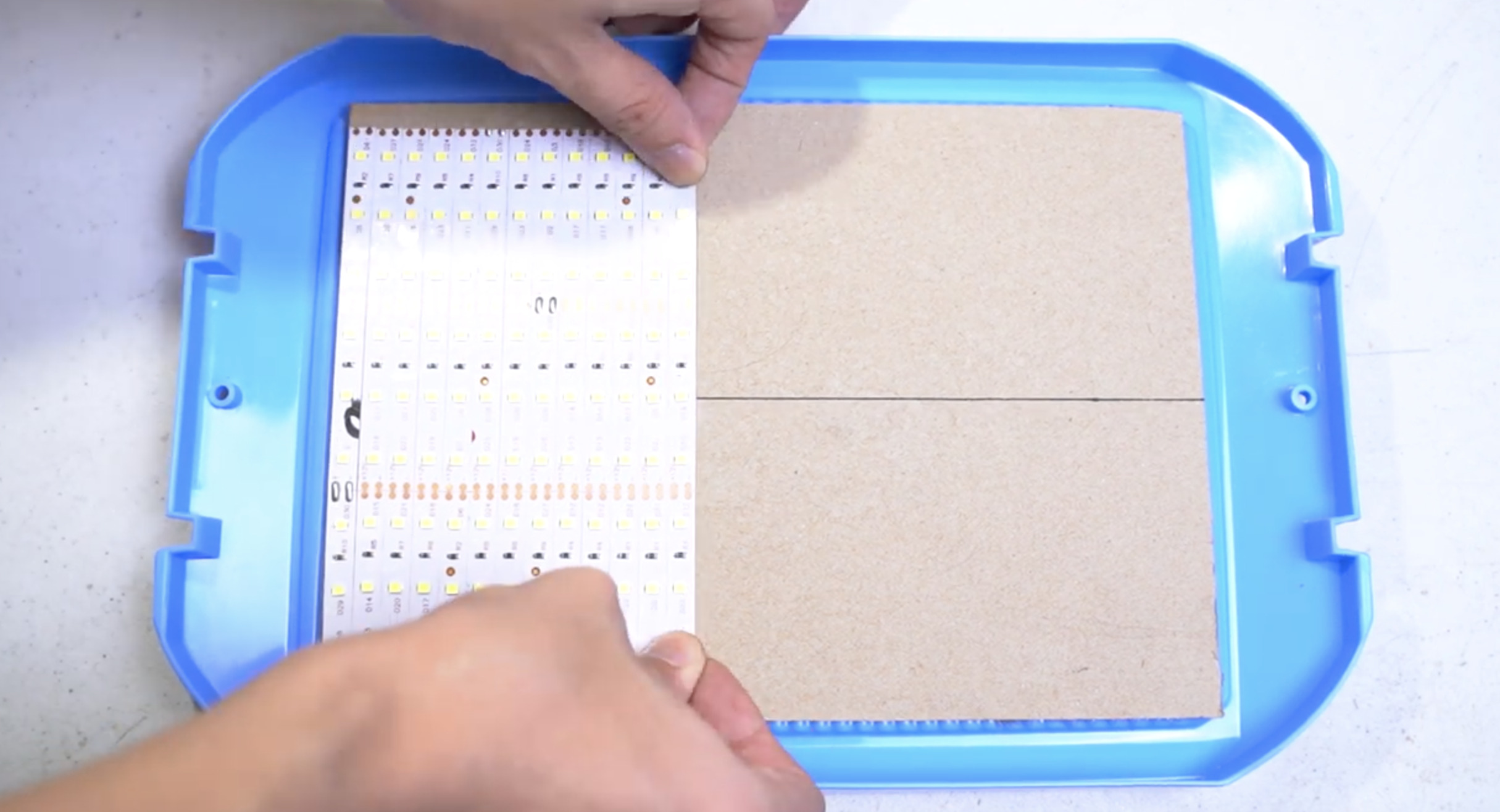
1. Prepare the top/cover of the enclosure. If the surface is not perfectly flat, you can put a layer of cardboard or any other material to make it flat.
2. Based on the width (or length, depending on the orientation you prefer) of the lid, cut the LED strips into pieces with equal length. Peel the cover off the back of the LED strips to expose the sticky side of the strips and gently mount the strips on the lid of your enclosure, ensuring there is little or no space between the strips.
3. Next solder the positive leads of the strips together on one side and the negative terminals together on the other side of the box. Soldering on different sides reduces the chances of shorts.
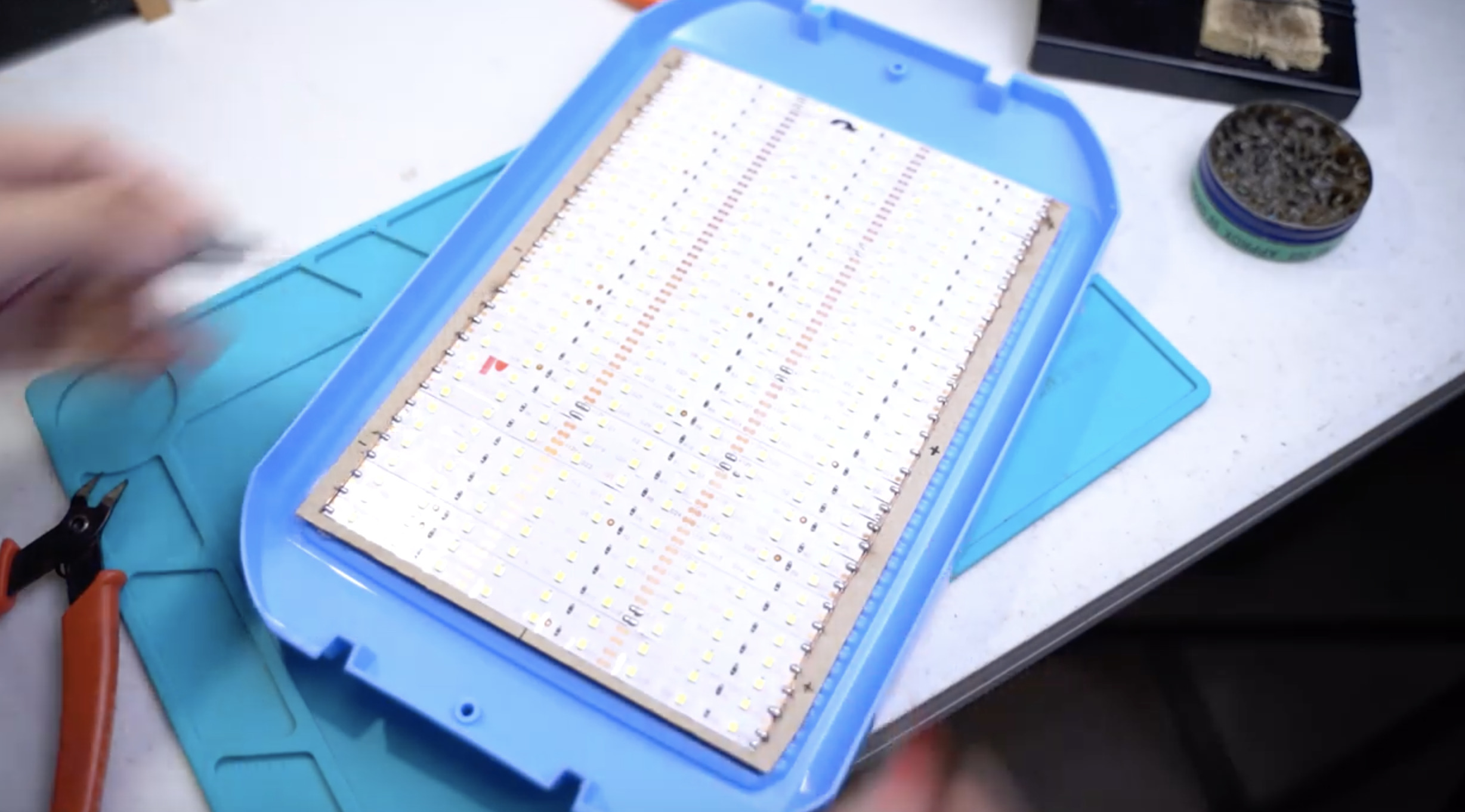
With this done, power the LEDs up with a 12VDC/2A supply to be sure there are no shorts. If your connections have been properly soldered, all LEDs should come on.
4. Next, you need to cut out holes for the screens, switch, and other elements that the users will interact with. You can do this with a CNC machine or a combination of drills, files, Dremel tools, and hot glue.
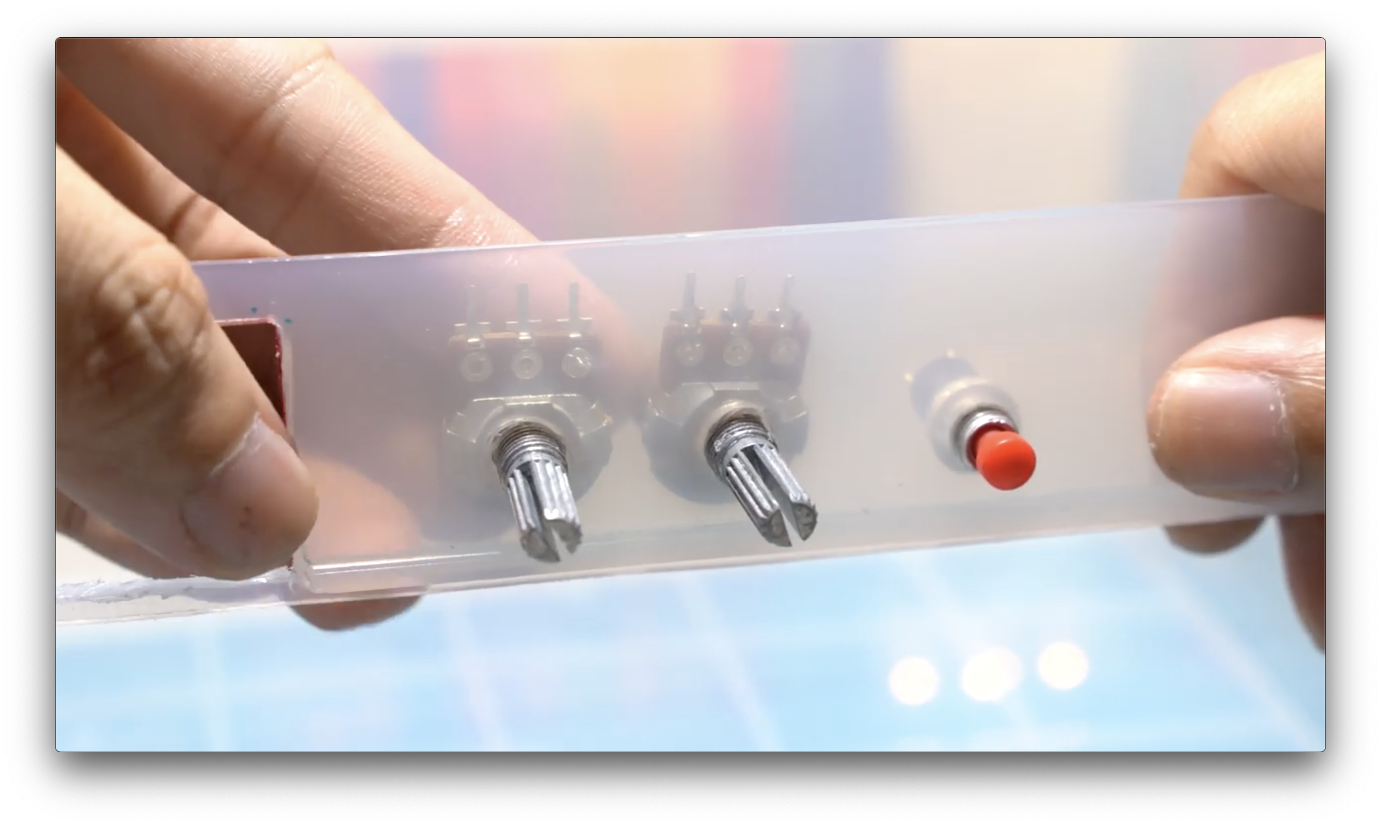
5. Connect all components and mount the external components in the holes made. feel free to use Hot glue to secure things in place where necessary.
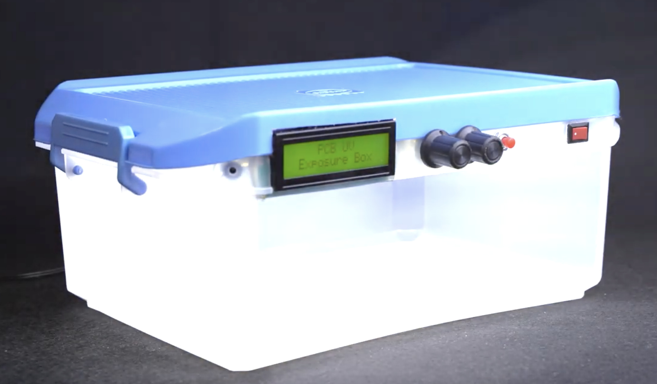
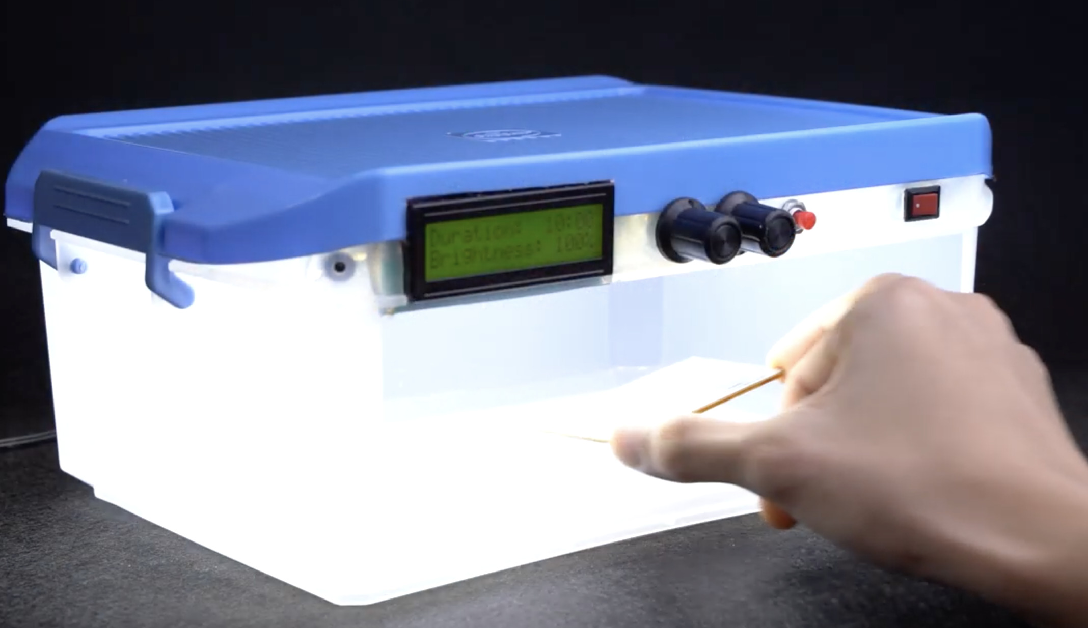
With all this in place, your enclosure should now be ready and look like the image below.
Code
With the enclosure ready, the next step is to write the code and upload it to the Arduino board. The operations of the device are quite straight forward; allow the user to set the desired exposure time via the potentiometer, turn on the LEDs, and initiate the countdown process with the progress being displayed on the LCD. When the preset time is reached, turn off the LEDs and initiate a beep on the buzzer so the user is notified.
To turn these these patterns into code, the Arduino IDE was used and since most of the heavy lifting associated with the code has to do with displaying data on the LCD, the Arduino LiquidCrystal Library was used.
As usual, I will do a quick breakdown of the code, explaining the concepts/parts of it that I feel might be difficult to follow.
The sketch starts with the include statements for the liquid crystal library along with a declaration of an instance of the library.
#include <LiquidCrystal.h>
LiquidCrystal lcd(7,6,5,4,3,2);
Next, some pin declaration is done with the pins of the Arduino to which different components are connected clearly laid out.
//----------PIN ASSIGNEMENTS-----------//
#define LEDs 11          //LED Transistor Trigger Pin
#define buzzer 10        //Buzzer Pin
#define button A4        //Select Button Pin
#define durationPot A0   //Duration Knob Pin
#define brightnessPot A2 //Brightness Knob Pin
Next, variables to hold different parameters including maximum countdown time, among others are declared and initialized.
//-------CONFIGURABLE PARAMETERS-------//
int
maxTime = 1200,          //Maximum countdown timer time (in secs)
buzzerFreq = 1000,       //Buzzer frequency (Hz, Change to customize tone)
glowDelay = 10;          //Change this to increase LED glow rate (0-200)
Next, system variables that are used to store different data during runtime are declared and initialized.
//---SYSTEM VARIABLES (DO NOT TOUCH)---//
float
timeLeftBarPercent = 0.00,
durationSecFloat = 0.00,
durationSecSelect = 0.00;
int
whitePWM = 0,
duration = 0,
durationSec = 0,
brightness = 0,
brightnessPercent = 0,
brightnessPWM = 0,
seconds = 0,
minutes = 0,
exposureLoop = 0,
startupLoop = 0;
unsigned long previousMillis = 0;
const long interval = 1000;
char timeMinSec[16];
Next, we write the void setup() function.
We start by setting the pinMode() of the output pins and initializing the LCD, after which some initialization and version control information is displayed.
//-VOID SETUP (Runs codes before entering loop)-//
void setup(){
  pinMode(LEDs,OUTPUT);
  pinMode(buzzer, OUTPUT);
  lcd.begin(16, 2);
  lcd.clear();

  brightnessPWM = map(analogRead(brightnessPot),0,1023,0,255);

  while(digitalRead(button)==LOW){
    lcd.setCursor(0,0);lcd.print("     PCB UV     ");
    lcd.setCursor(0,1);lcd.print("  Exposure Box  ");
    for (int i=0; i <= brightnessPWM; i++){
      analogWrite(LEDs,i);
      delay(glowDelay);
    }
    lcd.clear();
    lcd.setCursor(0, 0);lcd.print("Firmware Version");delay(500);
    lcd.setCursor(0, 1);lcd.print("TechBuilder v3.1");delay(500);
    break;
  }
  lcd.clear();
}
Next is the void loop() function.
This is where the functionality of the exposure box is defined and implemented. The system waits for the user to set the duration and brightness parameters and updates the display in realtime based on the values. Once the start button is pressed, the last duration valued set is stored, the LED is switched on and the exposure process starts. The duration is used for a countdown timer, and once it hits zero, the exposure process is halted by switching off the LEDs.
To restart the process, the user will have to press the reset button, set the duration and brightness, and press the button again to start the exposure process again.
void loop(){
  //--Gather Duration Knob Readings--//
  duration = analogRead(durationPot);
  durationSec = map(duration,0,1023,0, maxTime);

  //--Gather Brightness Knob Readings--//
  brightness = analogRead(brightnessPot);
  brightnessPercent = map(brightness,0,1023,0,100);
  brightnessPWM = map(brightness,0,1023,0,255);

  //--Control LED brightness in real time--//
  analogWrite(LEDs,brightnessPWM);

  minutes = durationSec/60;
  seconds = durationSec%60;

  lcd.setCursor(0,0);lcd.print("Duration: ");
  sprintf(timeMinSec,"%0.2d:%0.2d",minutes,seconds);
  lcd.setCursor(11,0);lcd.print(timeMinSec);

  if(brightnessPercent<100){  //Used this instead of "lcd.clear();" function. Done to reduce LCD flicker.
    lcd.setCursor(14, 1);
    lcd.print(" ");
  }

  lcd.setCursor(0, 1);
  lcd.print("Brightness:     ");
  lcd.setCursor(12, 1);
  lcd.print(brightnessPercent);
  lcd.setCursor(15, 1);
  lcd.print("%");

  if (digitalRead(button)==HIGH){
    durationSecSelect = durationSec;
    durationSecFloat = durationSec;

    lcd.clear();
    /*
    lcd.setCursor(0, 0);lcd.print(" Initializing  ");delay(300);
    lcd.setCursor(0, 0);lcd.print(" Initializing.  ");tone(buzzer, buzzerFreq*3, 100);delay(300);
    lcd.setCursor(0, 0);lcd.print(" Initializing.. ");tone(buzzer, buzzerFreq*3, 100);delay(300);
    lcd.setCursor(0, 0);lcd.print(" Initializing...");tone(buzzer, buzzerFreq*3, 100);delay(500);
    */
    lcd.setCursor(0,0);lcd.print("    STARTING    ");
    lcd.setCursor(0, 1);
    for (int i=0; i <= 15; i++){
      lcd.print((char) 255);delay(35);
      tone(buzzer, buzzerFreq*2, 50);
    }
    lcd.print((char) 255);
    delay(300);
    analogWrite(LEDs,brightnessPWM);

    lcd.clear();
    lcd.setCursor(0, 0);
    lcd.print("Time Left: ");

    while(exposureLoop==0){

      timeLeftBarPercent = 100*(durationSecFloat/durationSecSelect);

      unsigned long currentMillis = millis();
      if (currentMillis - previousMillis >= interval){
        previousMillis = currentMillis;

        minutes = durationSec/60;
        seconds = durationSec%60;

        sprintf(timeMinSec,"%0.2d:%0.2d", minutes, seconds);
        lcd.setCursor(11, 0);
        lcd.print(timeMinSec);

        if(timeLeftBarPercent<2)        {for (int v=0; v <= 15; v++){lcd.setCursor(v, 1);lcd.print((char) 255);}}
        else if(timeLeftBarPercent<6.25){for(int v=0; v <= 14; v++){lcd.setCursor(v, 1);lcd.print((char) 255);}}
        else if(timeLeftBarPercent<12.5){for(int v=0; v <= 13; v++){lcd.setCursor(v, 1);lcd.print((char) 255);}}
        else if(timeLeftBarPercent<18.75){for(int v=0; v <= 12; v++){lcd.setCursor(v, 1);lcd.print((char) 255);}}
        else if(timeLeftBarPercent<25)   {for (int v=0; v <= 11; v++){lcd.setCursor(v, 1);lcd.print((char) 255);}}
        else if(timeLeftBarPercent<31.25){for(int v=0; v <= 10; v++){lcd.setCursor(v, 1);lcd.print((char) 255);}}
        else if(timeLeftBarPercent<37.5) {for(int v=0; v <= 9; v++){lcd.setCursor(v, 1);lcd.print((char) 255);}}
        else if(timeLeftBarPercent<43.75){for(int v=0; v <= 8; v++){  lcd.setCursor(v, 1);lcd.print((char) 255);}}
        else if(timeLeftBarPercent<50)   {for(int v=0; v <= 7; v++){  lcd.setCursor(v, 1);lcd.print((char) 255);}}
        else if(timeLeftBarPercent<56.25){for(int v=0; v <= 6; v++){  lcd.setCursor(v, 1);lcd.print((char) 255);}}
        else if(timeLeftBarPercent<62.5) {for(int v=0; v <= 5; v++){  lcd.setCursor(v, 1);lcd.print((char) 255);}}
        else if(timeLeftBarPercent<68.75){for (int v=0; v <= 4; v++){lcd.setCursor(v, 1);lcd.print((char) 255);}}
        else if(timeLeftBarPercent<75)   {for (int v=0; v <= 3; v++){lcd.setCursor(v, 1);lcd.print((char) 255);}}
        else if(timeLeftBarPercent<81.25){for (int v=0; v <= 2; v++){lcd.setCursor(v, 1);lcd.print((char) 255);}}
        else if(timeLeftBarPercent<87.5) {for (int v=0; v <= 1; v++){lcd.setCursor(v, 1);lcd.print((char) 255);}}
        else if(timeLeftBarPercent<93.75){lcd.setCursor(0, 1);lcd.print((char) 255);}
        durationSec--;
        durationSecFloat--;
      }

      if(durationSec<=0){
        digitalWrite(LEDs,LOW);           //Turn off LEDs when countdown hits 0
        tone(buzzer,3000,500);
        lcd.setCursor(0,0);lcd.print("    Exposure    ");
        lcd.setCursor(0,1);lcd.print("    Finished    ");
        delay(500);lcd.clear();
        lcd.setCursor(0,0);lcd.print("  Press Button  ");
        lcd.setCursor(0,1);lcd.print("    To Start    ");
        delay(500);
        while(digitalRead(button)==LOW){}  //Press button to proceed with system restart
        for (int i=0; i <= 255; i++){      //Glow-up Illumination LED
          analogWrite(LEDs,i);
          delay(glowDelay);
        }
        lcd.clear();
        exposureLoop=1;
      }
      else if(digitalRead(button)==HIGH){
        digitalWrite(LEDs,LOW);
        tone(buzzer,3000,500);
        lcd.setCursor(0,0);lcd.print("   Cancelling   ");
        lcd.setCursor(0,1);lcd.print("    Process!    ");
        delay(750);
        lcd.setCursor(0,0);lcd.print("    Exposure    ");
        lcd.setCursor(0,1);lcd.print("    Finished    ");
        delay(500);lcd.clear();
        lcd.setCursor(0,0);lcd.print("  Press Button  ");
        lcd.setCursor(0,1);lcd.print("    To Start    ");

        while(digitalRead(button)==LOW){}
        for (int i=0;i<=brightnessPWM;i++){
          analogWrite(LEDs,i);
          delay(glowDelay);
        }
        lcd.clear();
        exposureLoop=1;
      }
    } //End of While
    exposureLoop=0;
  } //End Of Startup Button
  delay(20);
}//End of loop
The complete code for the project is provided below and attached under the download section.
#include <LiquidCrystal.h>
LiquidCrystal lcd(7,6,5,4,3,2);
//----------PIN ASSIGNEMENTS-----------//
#define LEDs 11          //LED Transistor Trigger Pin
#define buzzer 10        //Buzzer Pin
#define button A4        //Select Button Pin
#define durationPot A0   //Duration Knob Pin
#define brightnessPot A2 //Brightness Knob Pin
//-------CONFIGURABLE PARAMETERS-------//
int
maxTime = 1200,          //Maximum countdown timer time (in secs)
buzzerFreq = 1000,       //Buzzer frequency (Hz, Change to customize tone)
glowDelay = 10;          //Change this to increase LED glow rate (0-200)
//---SYSTEM VARIABLES (DO NOT TOUCH)---//
float
timeLeftBarPercent = 0.00,
durationSecFloat = 0.00,
durationSecSelect = 0.00;
int
whitePWM = 0,
duration = 0,
durationSec = 0,
brightness = 0,
brightnessPercent = 0,
brightnessPWM = 0,
seconds = 0,
minutes = 0,
exposureLoop = 0,
startupLoop = 0;
unsigned long previousMillis = 0;
const long interval = 1000;
char timeMinSec[16];

//-VOID SETUP (Runs codes before entering loop)-//
void setup(){
  pinMode(LEDs,                                      OUTPUT);
  pinMode(buzzer, OUTPUT);
  lcd.begin(16, 2);
  lcd.clear();

  brightnessPWM = map(analogRead(brightnessPot),0,1023,0,255);

  while(digitalRead(button)==LOW){
    lcd.setCursor(0,0);lcd.print("     PCB UV     ");
    lcd.setCursor(0,1);lcd.print("  Exposure Box  ");
    for (int i=0; i <= brightnessPWM; i++){
      analogWrite(LEDs,i);
      delay(glowDelay);
    }
    lcd.clear();
    lcd.setCursor(0, 0);lcd.print("Firmware Version");delay(500);
    lcd.setCursor(0, 1);lcd.print("TechBuilder v3.1");delay(500);
    break;
  }
  lcd.clear();
}
//-VOID LOOP (Code that runs on repeat)-//
void loop(){
  //--Gather Duration Knob Readings--//
  duration = analogRead(durationPot);
  durationSec = map(duration,0,1023,0, maxTime);

  //--Gather Brightness Knob Readings--//
  brightness = analogRead(brightnessPot);
  brightnessPercent = map(brightness,0,1023,0,100);
  brightnessPWM = map(brightness,0,1023,0,255);

  //--Control LED brightness in real time--//
  analogWrite(LEDs,brightnessPWM);

  minutes = durationSec/60;
  seconds = durationSec%60;

  lcd.setCursor(0,0);lcd.print("Duration: ");
  sprintf(timeMinSec,"%0.2d:%0.2d",minutes,seconds);
  lcd.setCursor(11,0);lcd.print(timeMinSec);

  if(brightnessPercent<100){  //Used this instead of "lcd.clear();" function. Done to reduce LCD flicker.
    lcd.setCursor(14, 1);
    lcd.print(" ");
  }

  lcd.setCursor(0, 1);
  lcd.print("Brightness:     ");
  lcd.setCursor(12, 1);
  lcd.print(brightnessPercent);
  lcd.setCursor(15, 1);
  lcd.print("%");

  if (digitalRead(button)==HIGH){
    durationSecSelect = durationSec;
    durationSecFloat = durationSec;

    lcd.clear();
    /*
    lcd.setCursor(0, 0);lcd.print(" Initializing  ");delay(300);
    lcd.setCursor(0, 0);lcd.print(" Initializing.  ");tone(buzzer, buzzerFreq*3, 100);delay(300);
    lcd.setCursor(0, 0);lcd.print(" Initializing.. ");tone(buzzer, buzzerFreq*3, 100);delay(300);
    lcd.setCursor(0, 0);lcd.print(" Initializing...");tone(buzzer, buzzerFreq*3, 100);delay(500);
    */
    lcd.setCursor(0,0);lcd.print("    STARTING    ");
    lcd.setCursor(0, 1);
    for (int i=0; i <= 15; i++){
      lcd.print((char) 255);delay(35);
      tone(buzzer, buzzerFreq*2, 50);
    }
    lcd.print((char) 255);
    delay(300);
    analogWrite(LEDs,brightnessPWM);

    lcd.clear();
    lcd.setCursor(0, 0);
    lcd.print("Time Left: ");

    while(exposureLoop==0){

      timeLeftBarPercent = 100*(durationSecFloat/durationSecSelect);

      unsigned long currentMillis = millis();
      if (currentMillis - previousMillis >= interval){
        previousMillis = currentMillis;

        minutes = durationSec/60;
        seconds = durationSec%60;

        sprintf(timeMinSec,"%0.2d:%0.2d", minutes, seconds);
        lcd.setCursor(11, 0);
        lcd.print(timeMinSec);

        if(timeLeftBarPercent<2)        {for (int v=0; v <= 15; v++){lcd.setCursor(v, 1);lcd.print((char) 255);}}
        else if(timeLeftBarPercent<6.25){for(int v=0; v <= 14; v++){lcd.setCursor(v, 1);lcd.print((char) 255);}}
        else if(timeLeftBarPercent<12.5){for(int v=0; v <= 13; v++){lcd.setCursor(v, 1);lcd.print((char) 255);}}
        else if(timeLeftBarPercent<18.75){for(int v=0; v <= 12; v++){lcd.setCursor(v, 1);lcd.print((char) 255);}}
        else if(timeLeftBarPercent<25)   {for (int v=0; v <= 11; v++){lcd.setCursor(v, 1);lcd.print((char) 255);}}
        else if(timeLeftBarPercent<31.25){for(int v=0; v <= 10; v++){lcd.setCursor(v, 1);lcd.print((char) 255);}}
        else if(timeLeftBarPercent<37.5) {for(int v=0; v <= 9; v++){lcd.setCursor(v, 1);lcd.print((char) 255);}}
        else if(timeLeftBarPercent<43.75){for(int v=0; v <= 8; v++){  lcd.setCursor(v, 1);lcd.print((char) 255);}}
        else if(timeLeftBarPercent<50)   {for(int v=0; v <= 7; v++){  lcd.setCursor(v, 1);lcd.print((char) 255);}}
        else if(timeLeftBarPercent<56.25){for(int v=0; v <= 6; v++){  lcd.setCursor(v, 1);lcd.print((char) 255);}}
        else if(timeLeftBarPercent<62.5) {for(int v=0; v <= 5; v++){  lcd.setCursor(v, 1);lcd.print((char) 255);}}
        else if(timeLeftBarPercent<68.75){for (int v=0; v <= 4; v++){lcd.setCursor(v, 1);lcd.print((char) 255);}}
        else if(timeLeftBarPercent<75)   {for (int v=0; v <= 3; v++){lcd.setCursor(v, 1);lcd.print((char) 255);}}
        else if(timeLeftBarPercent<81.25){for (int v=0; v <= 2; v++){lcd.setCursor(v, 1);lcd.print((char) 255);}}
        else if(timeLeftBarPercent<87.5) {for (int v=0; v <= 1; v++){lcd.setCursor(v, 1);lcd.print((char) 255);}}
        else if(timeLeftBarPercent<93.75){lcd.setCursor(0, 1);lcd.print((char) 255);}
        durationSec--;
        durationSecFloat--;
      }

      if(durationSec<=0){
        digitalWrite(LEDs,LOW);           //Turn off LEDs when countdown hits 0
        tone(buzzer,3000,500);
        lcd.setCursor(0,0);lcd.print("    Exposure    ");
        lcd.setCursor(0,1);lcd.print("    Finished    ");
        delay(500);lcd.clear();
        lcd.setCursor(0,0);lcd.print("  Press Button  ");
        lcd.setCursor(0,1);lcd.print("    To Start    ");
        delay(500);
        while(digitalRead(button)==LOW){}  //Press button to proceed with system restart
        for (int i=0; i <= 255; i++){      //Glow-up Illumination LED
          analogWrite(LEDs,i);
          delay(glowDelay);
        }
        lcd.clear();
        exposureLoop=1;
      }
      else if(digitalRead(button)==HIGH){
        digitalWrite(LEDs,LOW);
        tone(buzzer,3000,500);
        lcd.setCursor(0,0);lcd.print("   Cancelling   ");
        lcd.setCursor(0,1);lcd.print("    Process!    ");
        delay(750);
        lcd.setCursor(0,0);lcd.print("    Exposure    ");
        lcd.setCursor(0,1);lcd.print("    Finished    ");
        delay(500);lcd.clear();
        lcd.setCursor(0,0);lcd.print("  Press Button  ");
        lcd.setCursor(0,1);lcd.print("    To Start    ");

        while(digitalRead(button)==LOW){}
        for (int i=0;i<=brightnessPWM;i++){
          analogWrite(LEDs,i);
          delay(glowDelay);
        }
        lcd.clear();
        exposureLoop=1;
      }
    } //End of While
    exposureLoop=0;
  } //End Of Startup Button
  delay(20);
}//End of loop
Demo
With the code complete, connect the Arduino nano board to your computer and upload the code to it. Ensure to select the right board type and COM port as the case may be.
After the upload, power up your device. You should see the LCD come up with the initialization messages being displayed. Feel free to test things out with any design, you should see more efficient design transfer than with heat or any other method.
That’s it. Your very own PCB Exposure BOX. Feel free to reach out via the comment section if you have any questions about this build.
Project credit goes to Techbuilder, and a video version of the tutorial is available on youtube here.
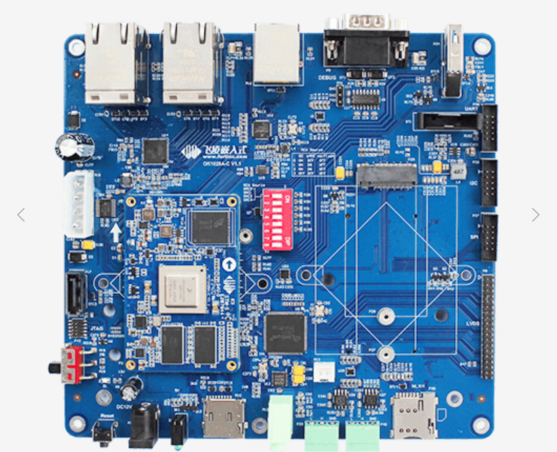
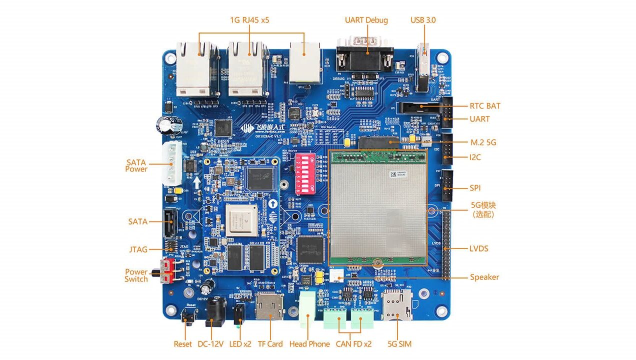
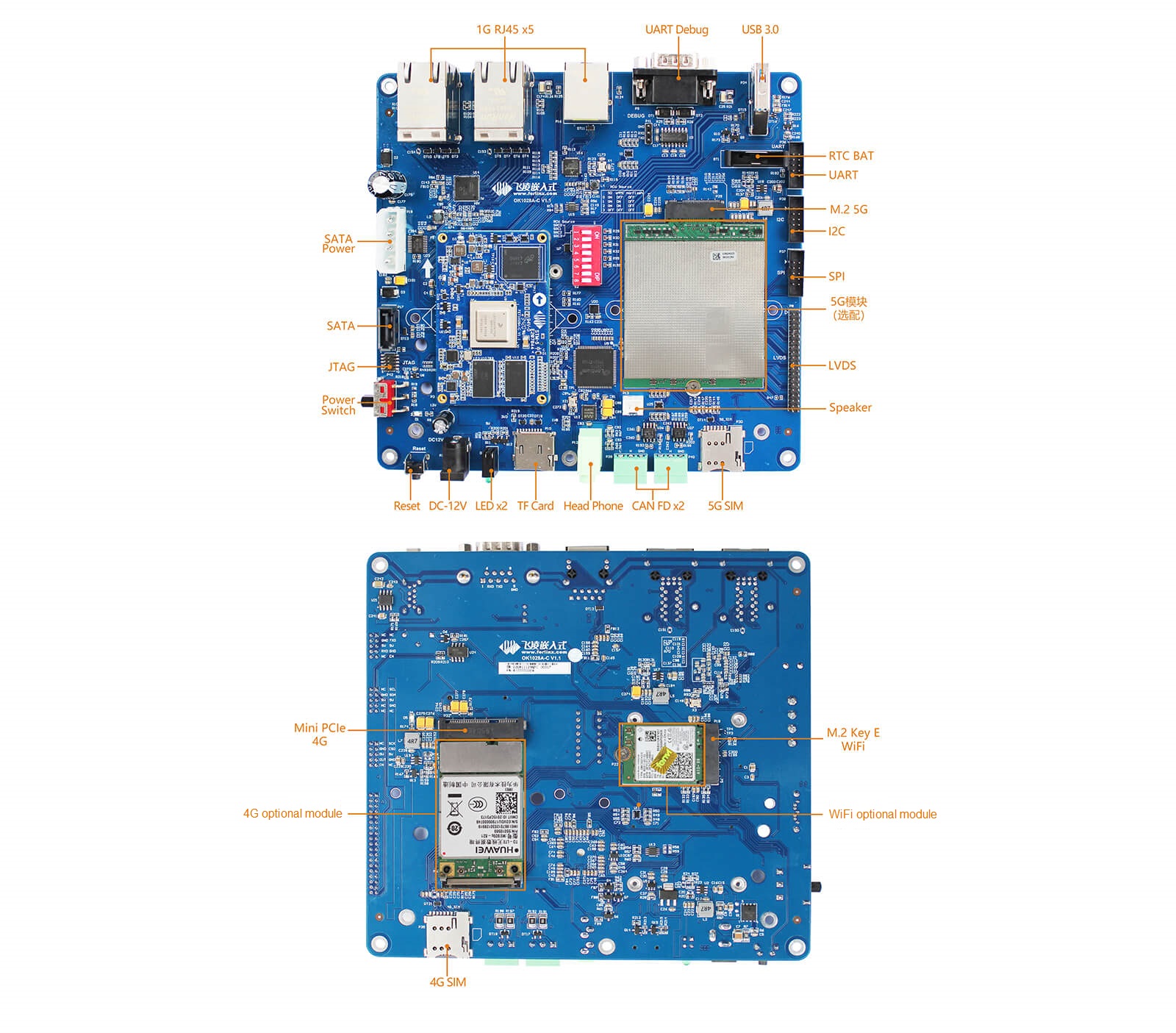

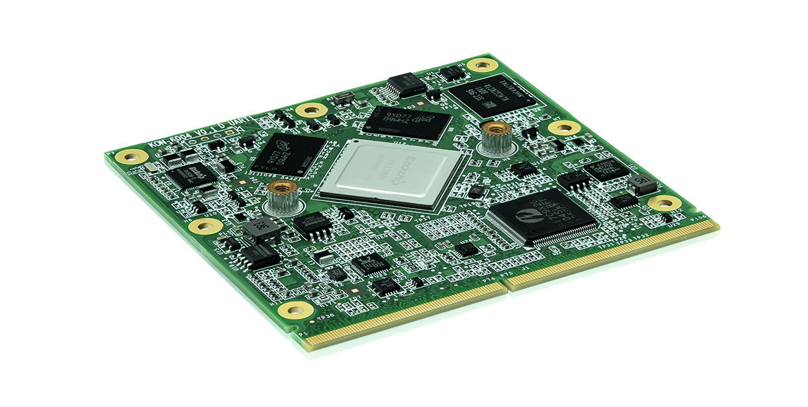
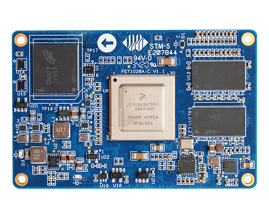
 The 65 x 42mm FET1028A-C module comes with 2GB DDR4 and 8GB eMMC memory. Other features include the support for DP 1.3 and eDP 1.4 interfaces up to 4Kp60. Available I/Os are 2x USB 3.0, 2x CAN FD, 4x UART, 6x I2C, 6x I2S, 2x SPI, and SD 3.0. The module has a robust operating temperature range of -40 to 85℃.