Lantronix Launches Open-Q™ 610 μSOM and Open-Q 610 Development Kit

Lantronix had announced its new Lantronix Open-Q™ 610 μSOM based on the powerful Qualcomm® QCS610 System on Chip (SOC). This micro System on Module (µSOM) is designed for connected visual intelligence applications with high-resolution camera capabilities, on-device artificial intelligence (AI) processing and native Ethernet interface. They also released a Qualcomm camera-focused development kit that run linux and an AI enabled octa-core Qcs610 Soc with triple 4-lane MIPI-CSI interfaces priced At $995 with shipments due in November. About the Open-Q 610 μSOM Paul Pickle, CEO of Lantronix says:

“Our long and successful relationship with Qualcomm Technologies enables us to deliver powerful micro SOM solutions that can accelerate IoT design and implementation, empowering innovators to create IoT applications that go beyond hardware and enable their wildest dreams”

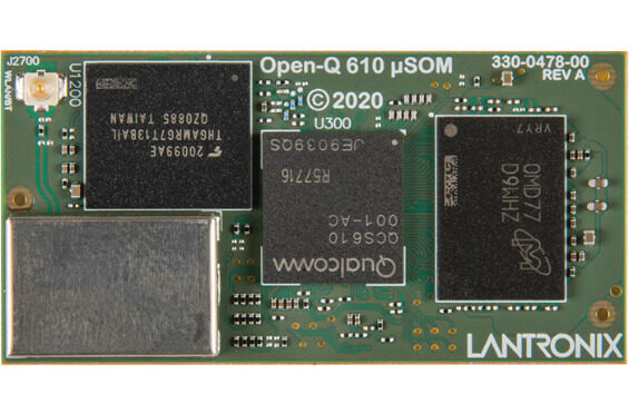
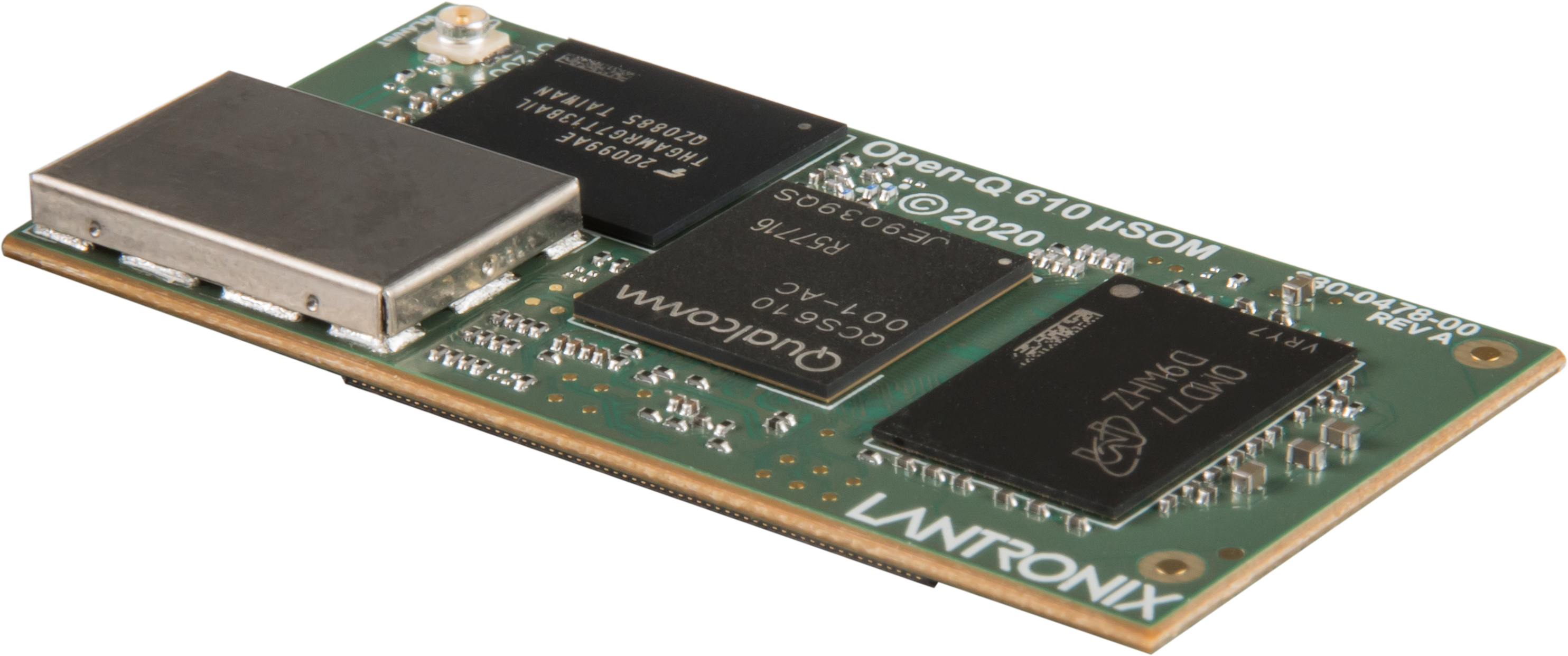
Lantronix’s Open-Q™ 610 μSOM is an ultra-compact (50mm x 25mm) production-ready SOM based on the powerful QCS610 SoC, with built-in Neural Processing Engine for on-device edge AI capabilities. Aimed at connected visual intelligence applications, with advanced built-in image sensor processing such as staggered HDR, lens de-warp, dual camera stitching, and image de-fog, the 610 μSOM is the ideal platform for your next smart camera product. Available with a full-featured development kit for ease of evaluation and POC development, the platform is supported by a Yocto Linux SDK with Qualcomm optimizations, GStreamer audio/video framework, and AI support for TensorFlow Lite and Qualcomm SNPE.

The Open-Q 610 µSOM provides the core computing capabilities for:

  • Image processing
  • Artificial intelligence
  • Advanced audio processing
  • Low power sensor processing

The new Lantronix Open-Q 610 μSOM is based on the powerful Qualcomm QCS610 SOC, the latest in the Qualcomm® Vision Intelligence Platform lineup targeting smart cameras with edge computing. Delivering up to 50 percent improved AI performance than the previous generation as well as image signal processing and sensor processing capabilities, it is designed to bring smart camera technology, including powerful artificial intelligence and machine learning features formerly only available to high-end devices, into mid-tier camera segments, including smart cities, commercial and enterprise, homes and vehicles.

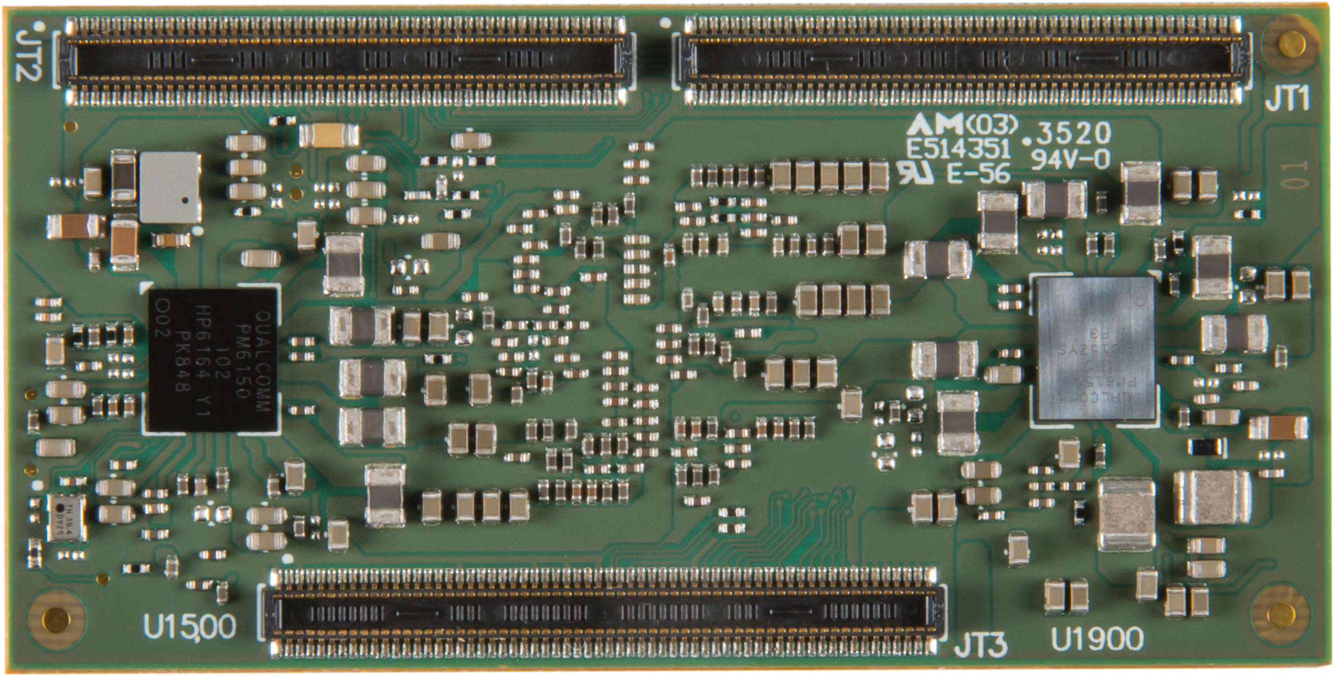
The Open-Q 610 μSOM follows other 50 x 25mm Intrinsyc μSOM modules such as Snapdragon 845 based Open-Q 845 uSOM. The Open-Q 610 μSOM ships with 2GB LPDDR4x and 16GB eMMC. The module integrates a native GbE controller and a Qualcomm WCN3980 module with dual-band 802.11a/b/g/n/ac and Bluetooth 5.x. Media interfaces include 3x 4-lane MIPI-CSI, 4-lane MIPI-DSI, DP 1.4 with Type-C support, and SLIMBus, SoundWire, and MI2S audio. Other I/O includes USB 3.1 and 2.0 plus SD, UART, I2C, SPI, and GPIOs. The 3.7V module is equipped with a PMIC.

Open-Q 610 Development Kit

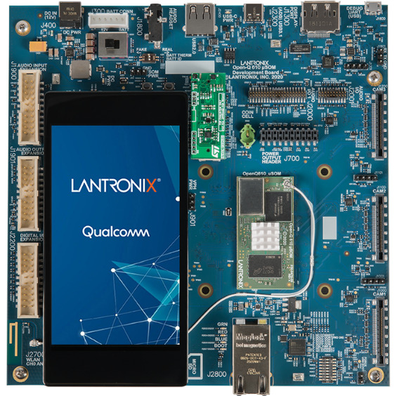
The companion Open-Q 610 Development Kit is a full-featured platform with available software tools, documentation, and optional accessories. It delivers everything required to immediately begin evaluation and initial product development. The development kit integrates the production-ready Open‐Q 610 µSOM with a carrier board, providing numerous expansion and connectivity options to support the development and testing of peripherals and applications. The development kit, along with the available documentation, also provides a proven reference design for custom carrier boards, providing a low-risk fast track to market for new products. The Open-Q 610 μSOM Development Kit is equipped with a single GbE, USB 3.1 Type-C, USB 2.0 host, and micro-USB serial debug ports. Available also is a dedicated DP 1.4 port that can be deactivated when running the Linux SDK.

There is no price available for the open-Q 610 μSOM. However, the Open-Q 610 μSOM Development Kit is available for pre-order at $995, with shipments due in November. More information about specification and documentation can be found on the Lantronix announcement, Open-Q 610 μSOM and Open-Q 610 μSOM Development Kit product pages, with the latter showing a shopping link.

Brushed DC Motor Speed and Direction Controller Using Joystick

This DC Motor controller provides direction and speed control of a brushed DC motor using a Joystick. This is an Arduino compatible open-source hardware with various applications. It can be used to control scissor lift motor, Linear actuator, Camera slider, camera pan-tilt head, curtain motor, power window motor, robotics, smart furniture automation, hospital furniture automation, projector up/down controller, TV up/down controller are few application examples. The board provides superb performance, smooth movement of motor, and hassle-free use. You only need to connect the motor wires, power the board, and you ready to go.

The controller has 3 main elements, Atmega328 Micro-Controller, LMD18201 DC Motor H-bridge, and Joystick connected to A0 Analog pin of microcontroller.  This board can control DC motor up to 48V DC with continuous current up to 3A and peak current 6A.

Brushed DC Motor Speed and Direction Controller Using Joystick – [Link]

DT-BL10 – Low-Power IoT Development Board Powered by RISC-V Core

DT-BL10 is a development board powered by BL602 WiSoC that sells for around $5. This board is specifically designed to work with a 32-bit RISC-V CPU with dynamic frequency from 1MHz to 192MHz. It has a 276KB SRAM and 128KB ROM.

The main focus of this board is on its wide range of wireless support. It has the support for Wi-Fi 4 802.11 b/g/n and Bluetooth 5.0 Low Energy. Wi-Fi security standards WPS/WEP/WPA/WPA2/WPA3 are available also with this low-power IoT application-focused board.

DT-BL10 Block Diagram

Moreover, a variety of security features such as secure boot, secure debug, XIP QSPI On-The-Fly AES Decryption (OTFAD), AES-128/192/256 are supported on this 49 × 26 × 3 mm board. Peripheral interfaces include SDIO, SPI, UART, I2C, IR remote, PWM, ADC, DAC, ACOMP, PIR, etc. Flexible GPIO configurations are supported. BL602 has a total of 16 GPIOs.

Board Specifications for the DT-BL10 :

  • SoC : Bouffalo BL602 RISC-V processor @ up to 192 Mhz with 276KB RAM, 128KB ROM with WiFi and Bluetooth
  • Wireless :
    • 2.4GHz 802.11b/g/n WiFI 4 up to 65 Mbps (802.11n) or 26 Mbps (802.11g)
    • Bluetooth LE 5.0
    • PCN antenna
  • Peripherals and I/Os :
    • SDIO 2.0 slave (AP-Host)
    • SPI master/slave, 2x UART, I2C master/slave, 5x PWM channels
    • ADC – 10-bit general DAC, 12-bit general ADC, 2x general analog comparators
    • PIR (Passive Infra-Red) detection
    • IR remote HW accelerator
    • 16x flexible GPIOs (BL602) / 23x flexible GPIOs (BL604)
    • 4x DMA channels
    • RTC timer up to One year
    • 2x 32-bit general-purpose timers
  • Supply Voltage : 3.0 to 3.6V
  • Power consumption : Deep-sleep mode: 22mA; deep standby mode: 2mA
  • Dimensions : 20 x 16 x 3mm
  • Temperature Range : -20°C to +85°C

Targeted toward the well-established low-power IoT applications, this board tries to rival the ESP8266 and ESP32 solutions which are already very affordable and community-supported. It may take the heat off from this competition with the implementation of the BL602 SoC. Time will tell if it can make an impact in the maker community. More information can be found on this product page.

PineCube Camera Dev Kit Powered by 5MP Omnivison OV5640

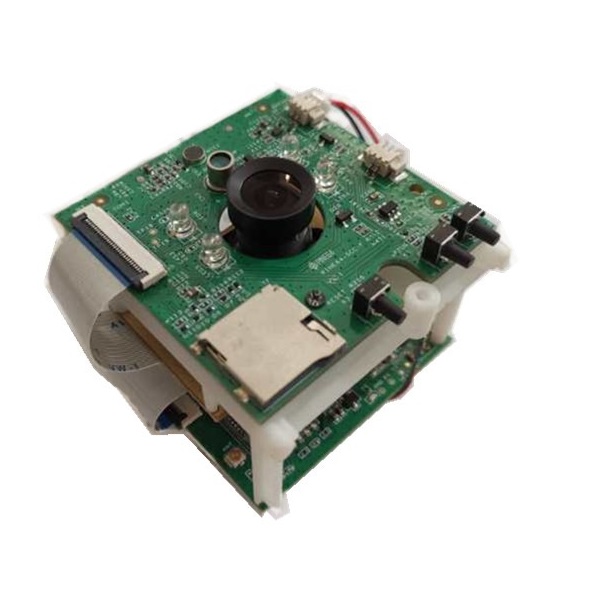
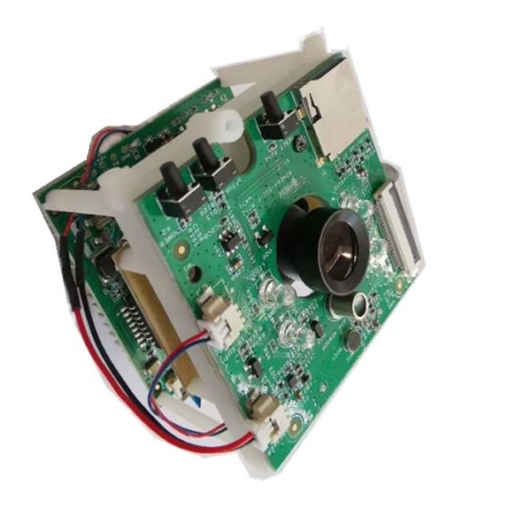
Pine64 announced its open-spec PineCube back in 2019 as a device called The Cube equipped with the 8-megapixel Sony iMX179 CMOS sensor. But for the technical issues with the Sony sensor, they changed it into a 5MP OmniVision OV5640 sensor and implemented the new name PineCube. The camera development kit has now shipped for $29.99.

The PineCube is powered by the SoC Cortex-A7 based Allwinner (Sochip) S3 clocked at 800MHz. This camera-application minded SoC allows 1080P@60fps decode and encode with support for up to two HD cameras. The OmniVision OV5640 is a 1/4 inch CMOS sensor that captures 2592 X 1944 @ 15fps and 1920 X 1080 @ 30fps video. It has an electronic rolling shutter with autofocus support for objects at 10cm-to-infinity distance. It comes with an adjustable control over brightness, contrast, color saturation, hue, gamma, white balance, and exposure. It has a FOV of 65-degree.

The PineCube

There is only a single RAM option of 128MB DDR3 and 26 pin GPIO for this 55 x 51.5 x 51mm 55gram board. Other features incorporate fast ethernet with passive PoE, 2.4GHz WiFi, micro-USB power, and USB 2.0 host ports, mic and speaker, and a bootable microSD slot. A battery pack and a 4.5-inch display are optional. The PineCube also offers an M12-compatible attachment. A variety of lens attachments are available for the kit.

PineCube Specification Summary :

  • Processor: Allwinner S3 (1x Cortex-A7 @ 800MHz)
  • Memory/storage:
    • 128MB DDR3
    • 128Mb SPI NOR flash
    • MicroSD slot (bootable)
  • Networking:
    • 10/100Mbps Ethernet port with passive PoE
    • 2.4GHz 802.11n/g/b
  • Sensor:
    • OmniVision OV5640 camera sensor — 5MP with M12 attachment for optional lenses
    • IR LED array for night vision
    • Photoresistor sensor
    • Mic, speakers, volume button
    • Optional 4.5-inch RGB LCD screen
  • Other I/O:
    • USB 2.0 host port
    • Micro-USB port for PD
    • 26-pin GPIO
  • Power: 5V/1A via micro-USB or 4-18V via PoE; optional 950-1600mAh Lithium Polymer Ion Battery Pack (model 903048)
  • Operating System: Linux SDK; supports NixOS, stock Linux

More information: The PineCube is available now for $29.99 on Pine64’s shopping and wiki pages.

Selpic Star A- The World’s Most Cost-Effective 3D Printer Hits Kickstarter for Only $99

Selpic Inc, a leading company focusing on digital printing solutions, has been developing innovative printing technologies since its foundation. Following the debut of Selpic P1, Selpic is going to launch the world’s most cost-effective 3D printer Star A on Kickstarter soon.

Star A is an ultra-compact and lightweight open-source 3D printer which is also easy to operate and set up. Most importantly, it supports extended functions, providing more possibilities of 3D printing.

Weighing 4.4 Ibs and measuring 10.29.49.8 inch, Star A is 3 times lighter than ordinary printers. With its compact body, Star A saves space and can be moved easily. Also, Star A is easy to assemble and set up. Its assembly can be finished within 4 steps. What you need to do is just turning screws, connecting 2 cables and setting filaments ready. Besides, 4 intuitive operating buttons can help with an easy reset, printing, filament feed and release.

With the X-axis and Y-axis accuracy of 100 μm and the Z-axis accuracy of 50 μm, Star A’s printing resolution is ±0.1 mm and its layer thickness can achieve 0.1~0.2 mm. Adopting low-noise motor, Star A keeps its working noise below 60 dB, which greatly improves the users’ experience. Besides, Star A has a resume-printing function. In the cases of an unexpected power outage or filament exhaustion, this function helps save filaments and improves printing efficiency.

It is worth mentioning that Star A is an open-source 3D printer. You can adjust the product parameters by modifying its code. We provide add-ons. By upgrading Star A’s parts, you can get the higher hotbed temperature up to 100 ℃ and 2.4 inch full-color and highly-sensitive touch screen. And with the laser head installed, you may have the laser engraving on the leather, cardboard, wood, etc.

Besides what is mentioned above, Star A has more surprises for you to explore. Should you be interested, Star A will meet you guys on Kiskstarter with only $99 pretty soon. Sign up now to enjoy the super early bird discount (50% off the $199 MSRP) for the first 100 backers only.

Learn more details from here: http://bit.ly/selpic3dks

Click the following link to participate in our giveaway activity and grab the chance of winning 3 units of Star A 3D printer: https://gleam.io/2Baaw/selpic-star-a

UPDATE 3/11/2020: Selpic Star A 3D printer will be launched on kickstarer.com at 6:00AM, Nov. 3, 2020, Pacific Time.

Brushed DC Motor Speed and Direction Controller Using Joystick

This DC Motor controller provides direction and speed control of a brushed DC motor using a Joystick. This is an Arduino compatible open-source hardware with various applications. It can be used to control scissor lift motor, Linear actuator, Camera slider, camera pan-tilt head, curtain motor, power window motor, robotics, smart furniture automation, hospital furniture automation, projector up/down controller, TV up/down controller are few application examples. The board provides superb performance, smooth movement of motor, and hassle-free use. You only need to connect the motor wires, power the board, and you ready to go.

The controller has 3 main elements, Atmega328 Micro-Controller, LMD18201 DC Motor H-bridge, and Joystick connected to A0 Analog pin of microcontroller.  This board can control DC motor up to 48V DC with continuous current up to 3A and peak current 6A.

Arduino Code

It is an Arduino compatible hardware and a new Atmega328 chip requires the burning of Bootloader to upload the Arduino code. Follow the below link for more info on programming and boot-loader burning.

The example code drives the DC motor with a joystick. I have used only 2 pins of LMD18201 chip, PWM, and Direction pin, I have not used the break pin, close the J1 jumper to free the break option of LMD182001. Open the jumper J1 in some applications if the user wants to use the Break option.

Click the download link at the end of the article to download the Arduino example code and test this hardware.

Arduino Pins Vs LMD18201 Motor Driver Pins

Arduino Digital D5>>PWM Pin LMD18201, Arduino Digital Pin D11 >> Direction Pin LMD18201, Analog Pin A1 >> Break Pin LMD18201, Analog pin A0 >> One Axis-Joystick

Power Supply

To run a 12V to 24V motor, the board requires a single power supply of 12V to 24V DC. To use this option Close the jumper 2 and power the CN2 wih 12V to 24V. To drive a Higher voltage motor, the circuit requires 2 separate power supplies, one for logic and one motor, in this case open the J2 jumper, use CN2 to apply motor supply 25V to 48V and CN1 7V to 24V logic supply.

Heat-sink

If you want to fetch full power from LMD18201 IC it is advisable to use a large size heatsink on the IC.

Features

  • Operating Power Supply 12V to 24V DC (for Motor 25V to 48V Power Refer to Note)
  • D1 Power LED
  • Joystick: Motor Direction CW/CCW and Speed Control
  • PWM Duty Cycle Adjustable 0 to 100% (Frequency 975Hz)
  • On Board Regulator L317 to Power 5V DC to Atmega328 Chip

LMD18201

The LMD18201 is a 3A H-Bridge designed for motion control applications. The device is built using a multi-technology process which combines bipolar and CMOS control circuitry with DMOS power devices on the same monolithic structure. The H-Bridge configuration is ideal for driving DC and stepper motors. The LMD18201 accommodates peak output currents up to 6A. Current sensing can be achieved via a small sense resistor connected in series with the power ground lead. For current sensing without disturbing the path of current to the load, the LMD18200 is recommended.

Schematic

Parts List

Connections

Gerber View

Photos


Video

LMD18201 Datasheet

Koki’o Project Case Goes Live On Crowdsupply

Cowfish Studio has announced the launch of the Koki’o Project Case on Crowdsupply. The Koki’o project case is an open frame design that allows for panoramic viewing of your PCB while protecting the board from harmful contact with hands or tools. The open design also allows entry of air and moisture, which is great for applications that require environmental exposure (i.e. sensors). A set of PCB template libraries are available for most major EDA tools (Eagle, Altium, KiCad) right out of the box. So instead of putting your PCB in a generic enclosure, you have the Koki’o Project Case which is so different from your generic PCB enclosure.

The Koki’o offers 4 versions of the case, they include:

  • Small 80 mm x 50 mm (3.15” x 1.97”)
  • Medium 100 mm x 60 mm (3.94”x 2.36”)
  • Large 120 mm x 70 mm (4.72” x 2.76”)
  • Extra Large 140 mm x 80 mm (5.51” x 3.15”).

The Koki’o case is a durable 18-gauge steel chassis, with a beautiful black powder paint finish. It features keyhole slots for mounting on walls and other surfaces, with its top plate formed from acrylic (PMMA). The Koki’o is available in 3D models, with an adjustable lid to accompany the expansion. The Koki’o is Ideal for prototyping or permanent installations.

Koki’o Steel Chasis

About Pledging, Cowfish Studio says:

“Each pledge level will come with a durable 18-gauge steel chassis with black powder paint finish and keyhole slots for wall mounting, a top plate formed from acrylic (PMMA), machine screws for mounting, two sets of standoffs to accommodate board expansion (5 mm and 10 mm), and protective non-skid rubber feet.” The Koki’o case is open source, and they say “Yes! We have greatly benefited from the open source community and we are dedicated to give back. The hardware is released under the Creative Commons ShareAlike 4.0 International (CC BY-SA 4.0).”

Regarding shipping, the Koki’o project case will be delivered to Crowd Supply’s warehouse for final distribution to backers worldwide. You can visit Crowd Supply’s guide on Ordering, Paying, and Shipping for more information about delivery, VAT payments, etc. All related documents, 3D models, and footprints are available on GitHub.

Features & Specifications:

  • Durable 18 Gauge Steel Chassis, Black Powder Paint Finish
  • Top Plate Formed From Acrylic (PMMA)
  • PCB Templates Compatible With Most Major EDA Tools (Eagle, Altium, KiCad)
  • 3D Models Available
  • Keyhole Slots for Wall Mounting
  • Ideal for Prototyping or Permanent Installations
  • Adjustable Lid to Accommodate Expansion

Cowfish Studio is reassuring those who have backed the board about the availability of the board. They say:

“In order to reduce the frustration of backers, we chose to work ahead of time and made sure that the project was as close as possible to mass production before launching this Crowd Supply campaign. The development and tooling costs are paid for and the funding required is purely to cover the costs of the production runs. They continue “We have suppliers lined up, and to the best of our knowledge, should be able to deliver without any problems.”

About the project, Cowfish studio says:

“We’re excited to announce the launch of the Koki’o Project Case. The project has moved along quite well. That doesn’t mean there weren’t challenges though—there were plenty and I’ll talk about some of them in future campaign updates! As always, a crowd funding campaign is only as successful as its backers make it, so I’m depending on you! I’m very excited about this project and the possibilities it enables, and I hope you are excited about it was well.”

Funding ends on Dec 09, 2020 at 03:59 PM PST (11:59 PM UTC). Visit the Crowdsupply campaign page for more information.

Network Traffic Visualizer

Have you ever wanted an indicator of how much the internet is being used at a particular time? You may want to know if your roomies are making it too slow for you to use, or just for the sole purpose of fun. For some reason, the router manufacturers usually do not include an indicator as such, but you do not need to be sad now. Because we are makers, we will make one! Or at least that was what Chandler McCowan from Hackster thought when creating a network traffic visualizer.

How would you make such a device? Easly, a packet sniffer! Hold up, calm yourself down, a packet sniffer is not the most legal thing to do, so we are not encouraging that sort of behavior (but seriously, if you can decrypt those packets, you are a god to me). With something similar to the likes of a packet forwarder, you can inspect the network and count how many packets are going through it. Seems difficult, but in reality, it is not. You can do such a thing with raw sockets, in an afternoon. It is a very good exercise if your goal is to understand the inner workings of the internet in practice, with UDP and TCP, and even go a bit beyond that.

Now, to the nitty-gritty of this project, Chandler made use of an ESP8266 and created a neat PCB to go along with it, housing 8 LEDs and a shift register to control them. Besides that, you get the necessary connectors to program the ESP board, so if you want to make changes to give it more functionalities or even use the kit in another different setting, you can, easily. Unfortunately, the kit does not allow you to be too creative, as there is no space to connect sensors or other peripherals, as most of the GPIO pins are occupied by the LED driver. On the flipside, it is designed to do one thing and does it well. You get a portable Wi-Fi “VU meter”. There is also an interesting 3D printed stand. But even if you feel underwhelmed by the project (which you should not, as it’s sole intend and purpose is to visualize the network), you can use it as a starting point and change it to your liking, as everything is open source: from the PCB schematic and files to the 3D printed stand and the Arduino code, you can access everything.

Lastly, this is still a work in progress, as there is a website currently under development that will provide all the information on this nifty project. While you wait, you can order it on Tindie for $15, which is a reasonable price for a finished product.

New Raspberry Pi 400 sells for $70 and is a computer in a compact keyboard

Raspberry Pi, whose mission is to put “affordable, high-performance, programmable computers into the hands of people all over the world”, has unveiled Raspberry Pi 400 which is a complete personal computer built into a compact keyboard.

“We’ve never been shy about borrowing a good idea. Which brings us to Raspberry Pi 400: it’s a faster, cooler 4GB Raspberry Pi 4, integrated into a compact keyboard”,

says Eben Upton, founder and CEO of Raspberry Pi.

Since more children are likely going to be dependent on remote learning in the coming months and more people working from home, the Raspberry Pi 400 might just be that affordable solution to many, especially students who are in need of a personal computer. It starts at a price that is a lot cheaper than some of the most budget phones and comes with a keyboard that’s big enough for proper writing. Just plug it into a monitor or a TV using any of its two micro HDMI ports, insert a microSD card, and attach a power cord and a mouse.

The Raspberry Pi 400 shares almost the same computer features as the Raspberry Pi 4, but with a little difference. The Raspberry Pi 400’s quad-core Cortex-A72 (Arm v8) 64-bit SoC runs at 1.8GHz while the Raspberry Pi 4’s SoC runs at 1.5GHz. The Pi 400 also offers only HDMI for audio output while the Raspberry Pi 4 has a 3.5mm audio and video jack.

Features and Specifications of the Raspberry Pi 400 include: 

  • CPU: 64-bit Broadcom BCM2711C0 quad-core ARM Cortex-A72 processor running at 1.8GHz
  • 4GB RAM
  • 1x microSD card slot
  • 2x USB 3.0, 1x USB 2.0 and 1x USB Type-C ports
  • 2x micro HDMI support dual display
  • Gigabit Ethernet
  • IEEE 802.11 b/g/n/ac WiFi (2.4GHz + 5GHz & Shielded)
  • Bluetooth 5.0 + Bluetooth Low Energy
  • 1x PCB antenna
  • Horizontal 40-pin GPIO header (right angle)
  • 2x micro HDMI ports
  • 1x built-in power button, and
  • Built-in Heat sink
  • Power Input: 5V via USB Type-C (up to 3A)
  • Dimensions: 285mm x 122mm x 21mm
  • Operating temperature: 0°C to +50°C

The Raspberry Pi 400 comes with its own OS but can be made to run a version of Windows. It is available and sells for $70 as a standalone machine or $100 as a ready-to-go kit that includes a mouse, USB-C power supply, microSD card, micro HDMI cable, and Raspberry Pi beginner’s guide. Hopefully, before the first half of next year, the Raspberry Pi 400 should be readily available around the world.

Further details on the computer may be found here.

Raspberry Pi Compute Module 4 Goes up For Sale Starting From $25

The Raspberry Pi Foundation has launched the Raspberry Pi Compute Module 4 (CM4)  starting at $25 price and offers up to 8GB RAM, Broadcom BCM2711 SoC with 4x 1.5GHz Cortex-A72 cores found on the RPi 4. The Compute Module 4 is built on the same 64-bit quad-core BCM2711 application processor as Raspberry Pi 4. However, the Compute Module 4 “delivers a step-change in performance over its predecessors: faster CPU cores, better multimedia, more interfacing capabilities, and, for the first time, a choice of RAM densities and a wireless connectivity option.” The Compute Module 4 also features LPDDR4-3200 RAM, but it’s the first with a GbE controller and the first with optional wireless. You can get 802.11b/g/n/ac and Bluetooth 5.0 BLE plus an optional external antenna for $5.

The Compute Module 4 features a brand new form factor and a compatibility break with earlier Compute Modules. It substitutes the SODIMM connector of the CM3+, CM3, and original Arm11-based CM1 to dual, high-density, 100-pin perpendicular connectors — one for power and low-speed interfaces found on the CM3/CM3+ and one for high-speed interfaces like PCIe. This significantly reduces the overall footprint of the module to a smaller 55 x 40 x 4.7mm footprint on its carrier board, enabling you to achieve smaller form factors for your products. Raspberry Pi Foundation is launching the CM4 in 32 variants, with four RAM options, four Flash options, and optional wireless connectivity. Prices range from $25 (for the 1GB RAM, Lite, no wireless variant) to $90 (for the 8GB RAM, 32GB Flash, wireless variant). Also, the four variants with 1GB RAM and no wireless keep the same price points ($25, $30, $35, and $40) as their Compute Module 3+ equivalents:

“once again, we’ve managed to pack a lot more performance into the platform without increasing the price.”

Compute Module 4 IO Board

Raspberry Pi Foundation is also launching an updated IO Board to help you get started with the Compute Module 4. Like the IO boards for earlier Compute Module products, this breaks out all the interfaces from the Compute Module to standard connectors, providing a ready-made development platform and a starting point for your own designs. The IO board features two full-size HDMI port, Gigabit Ethernet jack, two USB 2.0 ports, and MicroSD card socket (only for use with Lite, no-eMMC Compute Module 4 variants). It also enables x1 socket PCI Express Gen 2, HAT footprint with 40-pin GPIO connector and PoE header, 12V input via barrel jack (supports up to 26V if PCIe unused), Camera and display FPC connectors, and Real-time clock with battery backup. CAD for the IO board is available in KiCad format.

Antenna Kit and Compute Module 4

Available also is an optional, $5 Compute Module 4 Antenna Kit for situations where there’s a metal case that might block the internal antenna, or where it is not possible to provide the necessary ground plane cut-out under the module. The kit comes with a whip antenna with a bulkhead screw fixture and a U.FL connector. The highlight of the spec list includes:

  • 1.5GHz quad-core 64-bit ARM Cortex-A72 CPU
  • VideoCore VI graphics, supporting OpenGL ES 3.x
  • 4Kp60 hardware decode of H.265 (HEVC) video
  • 1080p60 hardware decode, and 1080p30 hardware encode of H.264 (AVC) video
  • Dual HDMI interfaces, at resolutions up to 4K
  • Single-lane PCI Express 2.0 interface
  • Dual MIPI DSI display, and dual MIPI CSI-2 camera interfaces
  • 1GB, 2GB, 4GB or 8GB LPDDR4-3200 SDRAM
  • Optional 8GB, 16GB or 32GB eMMC Flash storage
  • Optional 2.4GHz and 5GHz IEEE 802.11b/g/n/ac wireless LAN and Bluetooth 5.0
  • Gigabit Ethernet PHY with IEEE 1588 support
  • 28 GPIO pins, with up to 6 × UART, 6 × I2C and 5 × SPI

The Raspberry Pi Compute Module 4 is available now ranging from $25 to $90. You can also check CanaKit for the SKU. The IO Board costs $35 without a CM4 module. You can find more information on the Raspberry Pi Blog announcement and CM4 product page for shopping and additional documentation.

TOP PCB Companies