Artificial Intelligence (AI) has transformed various industries, offering transformative solutions that enhance efficiency, accuracy, and decision-making processes. iWave enables innovation at the edge with embedded platforms enhancing innovation at the edge for Artificial intelligence, Media processing, Robotics and visual computing.
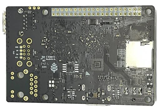
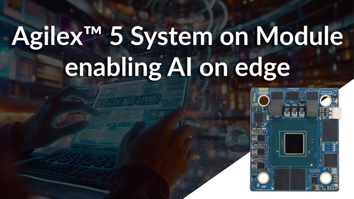
iWave is excited to launch iW-RainboW-G58M, powered by the Intel Agilex 5, which is the first FPGA with AI infused into the fabric. The SoM is built for applications in fields such as medical, robotics, and industry that need efficient, high-performance custom logic with AI/ML hardware support.
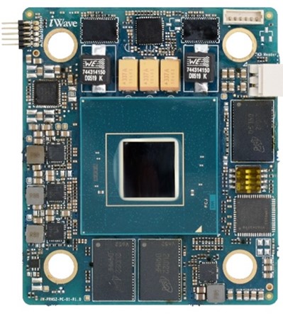
The System on Module (SoM) is built in a compact form factor of 60mm x 70mm and is compatible with the Intel Agilex® 5 FPGA and SoC E-Series family and B32A package in two device variants:
- Group A: A5E 065A/052A/043A/028A/013A SoC FPGA
- Group B: A5E 065B/052B/043B/028B/013B/008B SoC FPGA
Intel Agilex® 5 FPGAs and SoCs enhanced the industry’s first AI tensor block from Intel’s previous AI-optimized FPGA for general purpose, mid-range FPGAs in Intel Agilex® 5 FPGAs, making them an ideal choice for edge AI applications. The Agilex® 5 FPGA features an asymmetric applications processor system consisting of dual Arm Cortex-A76 cores and dual Cortex-A55 cores that optimize the performance and power efficiency of their workloads. Integrated with an enhanced DSP with AI Tensor block, the Agilex 5 offers advanced connectivity features such as High-speed GTS transceivers up to 28.1 Gbps and PCI Express ( PCIe ) 4.0 × 8, DisplayPort and HDMI Output.
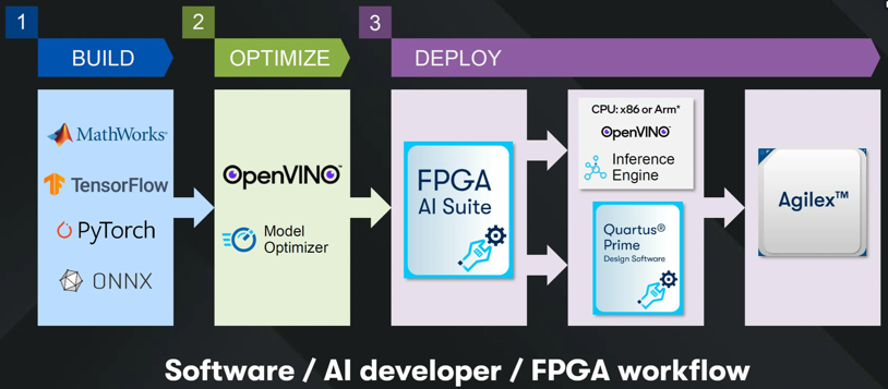
The AI/ML software capabilities start with popular platforms such as TensorFlow and PyTorch, including the support for the open-source OpenVINO toolkit that works with the FPGA AI Suite and Quartus Prime FPGA design software. The OpenVINO toolkit takes Deep Learning models from all the major Deep Learning frameworks (such as TensorFlow, PyTorch, Keras) and optimizes them for inference on a variety of hardware architectures, including various CPUs, CPU+GPU, and FPGAs. The Intel FPGA AI Suite was developed with the vision of ease-of-use of artificial intelligence (AI) inference on Intel FPGAs.
The suite enables FPGA designers, machine learning engineers, and software developers to create optimized FPGA AI platforms efficiently. Utilities in the Intel FPGA AI Suite speed up FPGA development for AI inference using familiar and popular industry frameworks such as TensorFlow or PyTorch and OpenVINO toolkit, while also leveraging robust and proven FPGA development flows with the Intel Quartus Prime Software.
iWave is now shipping early samples of the Agilex® 5 System on Module and evaluation kit, which comes with complete user documentation, software drivers, and a board support package. iWave provides their customers with an evaluation kit with the latest software packages to expedite their evaluation and time to market. Click here for watch the video on the System on Module and Evaluation Kit.
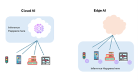
Cloud AI & Edge AI
Edge AI devices can process data, make decisions independently, operate with minimal latency, and derive valuable insights even in absence of network connectivity. Cloud AI processes data in remote data centers with high scalability but higher latency and security concerns, while Edge AI processes data locally on devices with lower latency and improved privacy.
This system consist of the edge node’s main function is to collect data from clients and perform intensive processing tasks where the devices can process data, independently make decisions, offer virtually no latency, and generate valuable insights when internet connections are down. And the data center can consolidate data from several edge nodes to utilize it in more sophisticated applications. This process not only helps in data privacy but offers low latency and covers the large bandwidth.
iWave maintains a product longevity program that ensures the System on Modules are available for long periods of time (10+ years). iWave offers customers extensive technical support during the evaluation and product development phase, alongside ODM Design services such as carrier card design, thermal simulation, and ODM as a business model.
iWave is an embedded systems engineering and solutions company, designing solutions for the Industrial, Medical, Automotive, and Avionics vertical markets. Building on a core competency of embedded System on Modules and embedded computing platforms enabling customers in their product development journey. Learn expertise since 1999, iWave boasts of an extensive portfolio of high-performance FPGA and SoC FPGA more about iWave at www.iwavesystems.com.