Intel Based 2.4-inch Mini PC’s “Take On” The CHUWI LarkBox

Mini PCs are not strange to us, we have been seeing them for a while now. Taiwanese ECS (Elitegroup computer systems) has been offering mini PCs over the years. They recently announced their pocket-sized model the LIVA Q , an upgraded version of Apollo lake SoCS  Which offers a choice of Gemini lake SoCs, a Micro pc that has a number of useful ports: a few USB ports (3.1 and 2.0) on one side, a micro SD card slot on the other side, an HDMI (2.0) and an Ethernet gigabit on the rear side. The resulting micro PC is wonderfully thin, consisting of a 33.4 mm (1.31) “square case of 70 mm (2.76′′) which can still be placed on a monitor ‘s back using the VESA bracket and screws included.

Chuwi another company dedicated to bringing top technology to customers all over the world recently designed a smaller Gemini lake mini PC with larkbox mini PC, lark box supports Windows 10 and linux distributions, the company recently upgraded the processor from a Celeron N4100 to a faster Celeron J4115 processor. Despite the invention of the larkbox, Chuwi has announced a smaller version of Micro PC’S, a new 2.4 inch mini PC form factor, called the XCY X51 2.4-inch Mini PC, and GMK has announced the GMK mini PC. We should note that GMK just started operating started in June 2019, and it comprises of R&D and production team which consists of Chuwi, Meizu, Telecast and Alldocube developers.


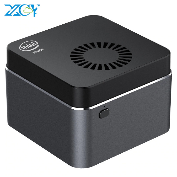
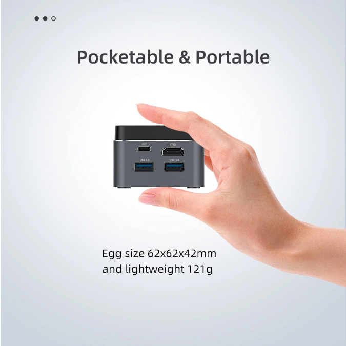
The XCY X51 2.4-INCH Mini PC is similar to the larkbox including having the same 12v/2A power adapter but has a slightly slower 6W Celeron N4100 processor compared to the 10W Celeron j4115 processor,  Although the processor is slower, the former has more RAM ( 8GB vs 6GB)  and a 128GB M.2 SSD instead of 128GB eMMC flash + an empty M.2 SSD socket. The XCY X51 2.4-INCH Mini PC product is available on Aliexpress for approximately $174 with Ali express Standard shipping.

The full specifications include:

  • SoC – Intel Celeron N4100 quad-core Gemini Lake processor @ 1.1 / 2.4 GHz with Intel UHD Graphics 600; 6W TDP
  • System Memory – 8GB LPDDR4
  • Storage – 128GB M.2 2242 SSD, MicroSD card slot
  • Video Output – HDMI 2.0 up to 4K @ 60 Hz
  • Audio – 3.5mm audio jack, digital audio via HDMI
  • Connectivity – Dual-band 802.11 b/g/n/ac WiFi 5 and Bluetooth 4.2
  • USB – 2x USB 3.0 ports, 1x USB Type-C port for power
  • Misc – Power button, cooling fan with “almost no noise”
  • Power Supply – TBD via USB-C port
  • Dimensions – 62 x 62 x 42 mm
  • Weight – 121 gram

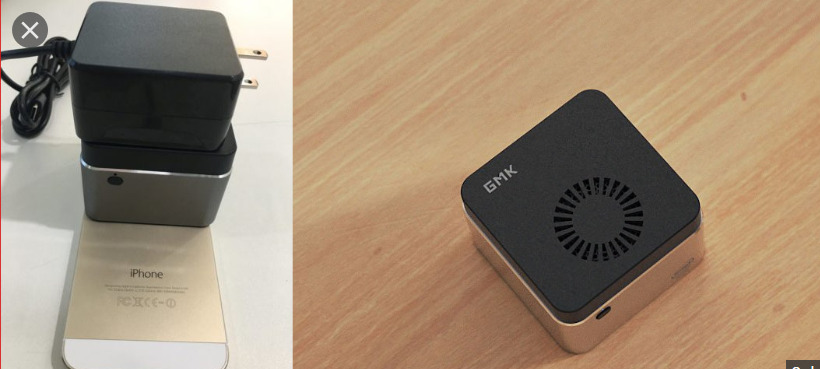
The GMK Mini PC has the same footprint design as its counterpart, but with little tweak in specifications, the only real difference is the processor’s speed with GMK having the faster Celeron J4125. Specifications for the GMK mini PC includes:

  • SoC – Intel Celeron J4125 quad-core Gemini Lake processor @ 2.5 / 2.7 GHz with Intel UHD Graphics 600; 10W TDP
  • System Memory – 8GB LPDDR4
  • Storage – 128GB M.2 2242 SSD, MicroSD card slot
  • Video Output – HDMI 2.0 up to 4K @ 60 Hz
  • Audio – 3.5mm audio jack, digital audio via HDMI
  • Connectivity – Dual-band 802.11 b/g/n/ac WiFi 5 2×2 MIMO and Bluetooth 4.2
  • USB – 2x USB 3.0 ports, 1x USB Type-C port for power
  • Misc – Power button, cooling fan with “almost no noise”
  • Power Supply – TBD via USB-C port
  • Dimensions – 62 x 62 x 42 mm
  • Weight – 125 grams

This product is not available yet, but they plan to release the GMK Mini PC on a crowdfunding platform in August/September.

They also offer original design manufacturer (ODM), which is also becoming a popular hardware manufacturing model among the IoT and AI startups. It enables the flexibility for the startups to create their solutions freely and have the hardware builders provide them with a fully customized platform, engineering, designed and branded for them, customers can make certain adjustments, such as changing the processor, memory, storage and color/marking of the enclosure.

You can visit GMK’s website for more information about their product.

Power USB devices from a vehicle

Automotive accessories such as PNDs (portable navigation devices) usually receive their power or charge using a simple adapter that a user plugs into a cigarette lighter. Sometimes, however, you may want to power or charge two devices at once. The circuit in Figure 1 can handle that task.

IC1 generates 5V from any 7.5 to 76V input—a wide enough range to include the complete range of car-battery voltage plus the 40V spike that can occur during a load dump. The IC is simple to use because it has an internal power switch and requires no compensation circuit.

Power USB devices from a vehicle – [Link]

MEMS Clock-System-on-a-Chip

SiTime Corporation, a leader in MEMS timing, has announced the launch of the Cascade family of MEMS clock ICs for 5G, wireline telecom and datacentre infrastructure.

The SiT9514x clock-system-on-a-chip (ClkSoC) family, consists of clock generators, jitter cleaners, and network synchronizers that are able to deliver multiple clock signals in a system. This family uses SiTime’s recently launched third-generation MEMS resonators that deliver higher performance with lower power.

Communications and enterprise electronics have previously used clock ICs with external quartz references to integrate multiple timing functions and to distribute clock signals. SiTime’s all-silicon clock architecture provides more integration by integrating a MEMS resonator reference inside the package. More importantly, the Cascade clock-system-on-a-chip is able to deliver up to 10 times higher reliability and resilience, enabling the 5G vision of zero downtime.

Either standalone or together with SiTime’s MEMS TCXOs and OCXOs, the SiT9514x is described as a complete timing solution that’s suitable for applications such as 5G RRUs, small cells, edge computers, switches, and routers.

“Our MEMS technology is well suited to solve the difficult timing challenges of emerging 5G infrastructure. This market represents a large growth opportunity for SiTime,” said Rajesh Vashist, CEO of SiTime. “The Cascade family is a natural next step for our timing business, but it also brings us closer to our customers. SiTime’s Cascade devices offer a complete clock-system-on-a-chip, which allows customers to simplify their designs and reduce time to market. As the only provider of MEMS resonators, oscillators, and clock ICs, and delivering system-level benefits to customers, SiTime continues to transform the $8 billion timing market.”

more information: www.sitime.com

New VIA Pixetto Vision Sensor Provides Support for Advanced Coding using Python and TensorFlow Lite

VIA Accelerates Artificial Intelligence and Machine Learning Education for Schools with VIA Pixetto

  • Full HD vision sensor with suite of pre-built Vision AI models, coding Blocks, and an online Accelerated Machine Learning platform
  • Compatible with Arduino, Raspberry Pi and micro:bit projects using Python and Tensorflow ML
  • On sale at VIA Online Store for US$85 + shipping

VIA Technologies, Inc. today announced the launch of the VIA Pixetto vision sensor, an intuitive and engaging platform for teaching Artificial Intelligence and Machine Learning to students aged twelve and above.

VIA Pixetto comes with an integrated suite of tools that make it easy for students to understand the basic principles and technologies underpinning AI and ML and apply them in their own AI vision, maker, and robotics projects. These tools include:

  • Pre-built object, shape, color, face, and handwriting recognition models that students can use to configure the vision sensor;
  • Beginner-friendly coding Blocks integrated with the popular Scratch platform to teach students basic programming;
  • Accelerated machine learning platform for students to create new models for their projects
  • Support for advanced coding using Python and TensorFlow Lite

The VIA Pixetto’s hardware features include a full HD vision sensor, a Micro USB 2.0 port, a Micro SD Card slot, a microphone, and a Grove connector for Arduino, micro:bit, and Raspberry Pi boards and peripherals.

“As Artificial Intelligence and Machine Learning proliferate across all aspects of our daily lives, it has never been more important for schools worldwide to equip their students with a theoretical and practical knowledge of these rapidly-emerging technologies,” commented Richard Brown, VP of International Marketing, VIA Technologies, Inc. “With the launch of VIA Pixetto, our goal is to address this need by providing an intuitive and engaging platform for students to learn the basics of AI and ML and explore their potential applications by creating their own projects.”

KEMET Releases New Tantalum Polymer Capacitors

KEMET released the Tantalum Stack Polymer (TSP) O 7360-43 and the 82uF/75V rated voltage extension in Polymer Hermetically Sealed. The TSP series was designed to allow for the highest capacitance/voltage (CV) ratings in surface mount device (SMD) capacitors.

The company’s KO-CAP® High Reliability Series T540, T541 and T543 are all available for stack configuration in the TSP series. The capacitors allow engineers to customize capacitance, voltage, and low equivalent series resistance (ESR), when stacked. The feature makes TSP suitable for devices using Gallium Nitride (GaN) semiconductor technology, including radar applications based on the Active Electronically Scanned Array (AESA) systems.

Per a company press release, a May 2020 report from Yole Développement* said the total defense market for GaN radio frequency (RF) applications is expected to grow at a CAGR of 22% and surpass USD 1 billion in 2025, while the total GaN RF market will reach over USD 2 billion in 2025. The report also states that application in AESA systems for radar and demand for lightweight devices for airborne systems are the main drivers of the GaN RF defense market.

For more information, visit https://ec.kemet.com/polymer-high-reliability/

12W Dimmer with Soft Start for 12V LEDs

The circuit presented here is a LED dimmer with a soft-start function. The board can drive a LED up to 12W and the circuit can manage a load up to 1A continuous with 12Vsupply. The circuit is built using SG3525 PWM IC and the IRFR120 MOSFET, SG3525 generates the PWM, and IRFR120 MOSFET drives the 12W max load. BC847 is used to invert the PWM signal from SG3525 and create a soft-start circuit. SG3525 has a soft-start function and the soft-start timing can be slowed down by increasing the capacitor C2 value to 22uF/16V.  Trimmer pot PR1 provided to adjust the PWM frequency from 210 Hz to 6.5Khz. Keeping PWM frequency lower is advisable for LED load. The intensity of the LED can be adjusted using the slider potentiometer P1. Optional small trimmer pot is provided in case slider pot is not available.  I have tried a LOG slider pot which is used in audio applications and a linear pot will have better linear dimming. The duty cycle upper limit can be restricted by changing R2. Use R2 0 Ohms or 1 Ohm for normal 0-100% duty output.

The circuit is designed to drive 12V LED or LED panels, so don’t connect directly any LED to this board, as LED forward voltage is 3.5V and they need a series resistor to control the current. Any LED, LED Panel, Light Pad of 12V, and current from 10mA to 1A can be connected to this board directly.

Direct drive of LED without a series resistor is possible by limiting the maximum current, choose the appropriate resistor value of R2 to achieve this.

Features

  • Supply 12V-15V DC
  • LED Load 10mA to 1A continuous
  • Frequency range 210Hz to 6.5Khz
  • Duty Cycle Span 0 to 100 %
  • D1 Power LED

Schematic

Parts List

Connections

Photos

Gerber View

Video

SG3525 Datasheet

iotSDR – Design custom IoT protocols & gateways

iotSDR is a versatile dev board with everything you need to design custom IoT protocols & gateways.

iotSDR provides a platform that allows SDR developers and enthusiasts to develop cutting-edge solutions in the IoT radio and network domains. It has two Microchip AT86RF215 frontends, capable of providing I/Q streams and modem functionality for the Xilinx ZYNQ SoC, as well as a MAX2769 GNSS chip for custom GPS, Galileo, BieDou, and Glonass development. It is also compatible with the popular GNURadio SDR software.

If you want to design and develop a physical layer protocol for IOT – a protocol like LoRa, SigFox, WightLess, Bluetooth, BLE, 802.15.4, ZigBee, or something of your own – this board is for you. It is also a great place to start if you want to build a custom IoT gateway along the lines of The Things Network, LPWAN, or Google Thread.

Features & Specifications

  • RF Transceiver: 2x Atmel AT86RF215
    • European band: 863-870 MHz / 870-876 MHz / 915-921 MHz
    • Chinese band: 470-510 MHz / 779-787 MHz
    • North American band: 902-928 MHz
    • Korean band: 917-923.5 MHz
    • Japanese band: 920-928 MHz
    • World-wide ISM band: 2400-2483.5 MHz
  • GNSS Receiver: MAX2769B
  • SoC: Xilinx ZYNQ XC7Z010-1CLG400C
    • Dual-Core ARM Cortex-A9 MPCore
    • 256 kb on-chip memory
    • DDR3 support
    • 28,000 logic cells
    • 17,600 LUTs
    • 2.1 Mb block RAM
    • 80 DSP slices
    • 2x UART, 2x CAN 2.0 B, 2x I²C, 2x SPI, 4x 32-bit GPIO
    • FPGA configuration via JTAG
  • EEPROM Memory: 1x AT24MAC602 for RF transciever MCU firmware and data
  • Flash Memory: 1x QSPI 128 Mb flash memory for firmware
  • RAM: 256 MB DDR3
  • SD Card: Micro SD card slot
  • General User Inputs/Outputs:
    • 2x 8-bit PL interfaces
    • 1x 8-bit PS interface
  • Connectivity:
    • 1x Gigabit Ethernet
    • USB 2.0 high-speed (USB3310)
    • USB 2.0 full-speed (CP2104)
    • 2x SMA RF connector for Low Frequency IoT Bands transceiver
    • 2x SMA RF connector for 2.4 GHz Band transceiver
    • 1x GNSS receiver RF connector
    • FPGA JTAG connector for external JTAG programmer/debugger
  • Clock System:
    • Single clock source for both RF frontends
    • Separate clock for GNSS receiver
  • Board Dimensions: 76.2 mm x 101.6 mm

The project will launch soon on www.crowdsupply.com

UPDATE 07/08/2020: The project is now live on CrowdSupply.com and starting from $299.

MEMS analog microphone sport high dynamic range, low power consumption

TDK  introduces the InvenSense ICS-40638 MEMS analog microphone. The ICS-40638 microphone offers an ultra-high Acoustic Overload Point (AOP) of 138 dB Sound Pressure Level (SPL), exceptionally efficient 170 µA low power operation and high Signal to Noise Ratio (SNR) of 63 dB in a small 3.5 mm x 2.65 mm x 0.98 mm bottom port surface‐mount package. The analog MEMS microphone is equipped with high dynamic range, operates up to 105°C, and is designed for IoT and consumer devices.

The new ICS-40638 microphone is ideal for wearable and IoT applications, particularly in outdoor, industrial or harsh environments, where high temperature and high acoustic overload points present system design challenges. The ICS-40638 includes a MEMS microphone element, an impedance converter, and a differential output amplifier. Other high‐performance specifications include a tight ±1 dB sensitivity tolerance and enhanced immunity to both radiated and conducted RF interference. The part is ideal for noise-canceling applications in challenging environments.

The InvenSense ICS-40638 part and the ICS-40638 evaluation board (EVB) are now available from multiple distributors worldwide

Reboot-o-matic is an Automatic power-cycling microcontroller and a DC power interrupting watchdog

Nick Sayer has posted on Hackaday his recent project, the Reboot-o-matic, which is a Automatic power-cycling microcontroller. The inspiration for the project came when he saw the need to monitor remotely some home automation devices in their vacation home over the internet remotely, but the router was not 100% reliable, so there were occasions where the Internet got stuck. For him to just power cycle the router, he built the Reboot-o-matic. This is perfect for creating a network monitoring watchdog for an unattended SOHO network router.

Nowadays most SoHo networking gears are powered by DC wall warts, so no need for a switch to be designed for the AC. All you need is just to add a P MOSFET in the positive DC rail. The MOSFET has a pull-down(the power has to be on default) on the gate, so having a second P MOSFET is important because the first MOSFET’s gate has to be raised up to the input voltage rail, and the one doing the raising or pulling is running at a lesser volt than that. However, the second P MOSFET’s gate is pulled up instead of pulling down. So that its default is always off. The gate of the 2nd P MOSFET has to be pulled up to the input rail and joined to a third MOSFET, which is an N channel one, having a gate that is pulled down and connected to a microcontroller pin.

A problem with powering the circuit at higher voltage is, the max gate voltage of the two MOSFETs must not be exceeded. To prevent this, you can add a Zener diode between the gate and positive rail and for the second P MOSFET, whose gate is pulled to the ground by N MOSFET, a current limiting resistor is added to the second P MOSFET serving as protection for the Zener diode. “This Rube Goldberg arranges allows us to use a low powered microcontroller to turn output power off briefly, but since everything are now “on” on default. imagine for example if the microcontroller failed to start. If we required an asserted output to switch on the power, then this failure would result in the power being off permanently. The microcontroller failing by reducing an output to Vcc is less likely.” The microcontroller for this project is a simple ATTiny9. Aside from the output, there is also an input pin that comes from the outside. The input has a protection diode that prevents any voltage fed into the pin from getting to the controller. The pin is described as an open-drain input. To request a power cycle, you short the pin to the ground.

The controller has a software debouncing in place, and the input has to go low for a full second before the power can be cycled and the power is cycled for 10 secs causing the input to go high and for one hour before any low transition is allowed. The microcontroller is powered from an LDO fed by the input power rail. The reason for adding a controller to the project is for the controller to have some rules to act as a fail-safe for the system. The microcontroller has software de-bouncing in place, to enable the input to go low and remain low for a full second before the power is cycled. The power cycle lasts for 10 seconds, and then the input has to go high and remain high for an hour before any low transition is allowed. Finally, the microcontroller is powered from an LDO fed by the input power rail.

this project is special because there are many other methods one could use – for example, a timer to power-cycle the device on a daily basis however, the Reboot-o-matic has an intelligent gatekeeper that only permits the power-cycle to happen at most once per hour. Also, the design attempts to ensure that any fault would result in the power state failing-on rather than off.

You can get the Reboot-o-matic on Tindie, starting for $15. More information can be found on the project page on Hackaday.

DIY GPS Tracker Features Three Arduino boards

Duane Bester has built a GPS Tracker From Scratch Using 3 Arduino boards to make a GPS tracker and a data logger. A flash of idea came to him, to combine the new Arduino Nano 33 BLE Sense with an SD card and GPS module for a project that records GPS and IMU data. So he opted to buy the Nano 33, the MKR Mem Shield, and the MKR GPS Shield and couple all of them together. He later found out that these boards aren’t footprint-compatible, so He combined them with a breadboard. It took time to get all the plugins installed and everything connected correctly. The biggest challenge he faced was the GPS module, and he says “It really helps to start debugging the GPS’ example code outside; where the satellite signal is available.” After successfully vetting the Prototype code for the arduino, he went ahead to build a custom PCB.

The plain PCB boards

For the PCB design, he used easyeda to build his custom PCB. The first thing he did was obtaining the schematics from the Nano 33, the MKR Mem Shield then the MKR GPS Shield. The schematic was easy to access via Github. Since they are Eagle schematic files, the Eagle trial version was used for an in-depth analysis. After that, he copied the full Nano 33 BLE schematic as it is, as well as matching up the component names and numbers. He then included the GPS module then he had to figure out how to program through J-Link. To ensure it’s optimal, he went on to send off the design to PCBWay to be built and coupled. This was a smooth process, with some questions concerning the part name and orientation. Few weeks later he received the plan PCB boards in the mail, then six weeks later he got the fully assembled PCB boards.


The fully assembled PCB board

When he wanted to flash the Arduino bootloader, he purchased the J-Link EDU Mini cable to be used for programming the custom board and all the J-Link drivers installed. He finally flashed the bootloader through nRF Connect, and it worked. An Arduino Nano would pop up and connect to his MacBook when he plugged in the USB cable. However, during the course of the build, he realized he had made a few mistakes in reverse engineering, the board. The mistakes he made includes:

The Nano 33 schematic has a Do Not Populate (DNP) for a pull-up resistor on the RESET pin. I should have added test points for this resistor as well. I ended up hand-soldering a 4.7K. This stopped my board from auto-resetting every second (could also adjust the UICR to disable the RESET pin).

The schematic shows a 1M Ohm resistor connecting the USB shield to the ground. But the Eagle file shows 330 Ohm , which should be 330 Ohms. (There is tons of debate and trade-offs here)
He messed up wire with the gesture sensor, so the sensor didn’t work. However, it still measured RGB colors.
He was able to fix the issues mentioned above.

To make the device portable, He added a battery connection, LiPo charging, and load sharing. The device was further equipped with a 5V and 3.3V power rail to power external devices. After making more research, He decided to add more decoupling capacitors and various connectors (including GPIO). Finally, he sent the new design with a more compact PCB layout to PCBWay, and he is currently waiting on the boards to get back. For more information about the project, visit the project page here

TOP PCB Companies