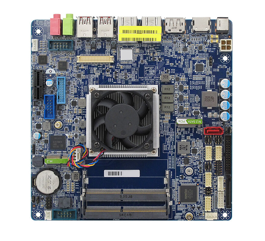
MX4305UE industrial mini-ITX motherboard is equipped with the latest Intel® Celeron® 4305UE processor onboard, codenamed Whiskey Lake, with integrated Intel® UHD Graphics 610 and a 15W TDP. The motherboard has a lifecycle of at least 5-7 years and is designed for power sensitive IoT devices built on 8th Gen Intel® Core i3/i5/i7 U series SoC processors. It is a price-performance balanced long-life mini-ITX ideal for embedded applications such as video and video wall control management system, point-of-sales systems (POS), kiosks, automated vending machines, panel PCs, digital signage, medical and gaming devices.
Intel® Celeron® 4305UE Whiskey Lake Processor mini-ITX Motherboard
Intel® Whiskey Lake Celeron 4305UE proessor onboard
Intel® UHD Graphics 610
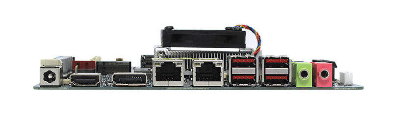
Display: supports triple displays simultaneously via 1 x DP1.2 (DP++) @60Hz (4096×2160), 1 x HDMI 2.0 @60Hz (4096×2160), 18/24 bits Dual Channel LVDS
Expansion: 1 x PCIe x1, 1 x 2230 M.2 E Key, 1 x 2280 & 2242 M.2 M Key NVMe for Wi-Fi/BT support
Ethernet: 2 x RJ-45 (Intel® I211-AT and Intel® I219-LM Gigabit)
USB: 4 x USB 3.1 Type A, 2 x USB 3.1, 2 x USB 2.0
COM Port: 1 x RS-232/422/485 and 3 x RS-232 Header
I2C connector onboard
Wide Range DC-in: 12V – 24V DC-in
TPM: hardware based TPM 2.0 onboard
6.7″ x 6.7″ (170mm x 170mm)
The MX4305UE is an “OEM product”. OEM products are designed for OEMs with ongoing and consistent order requirements and subject to minimum order quantities. Evaluation units are available without such restrictions. BCM has multiple stocking distributors that may be able to work with OEMs to streamline product deliveries. For general availability of the MX4305UE or interest in a semi-custom or complete turn-key custom design based on the Intel® Whiskey Lake processor platforms, please contact BCMSales@bcmcom.com.
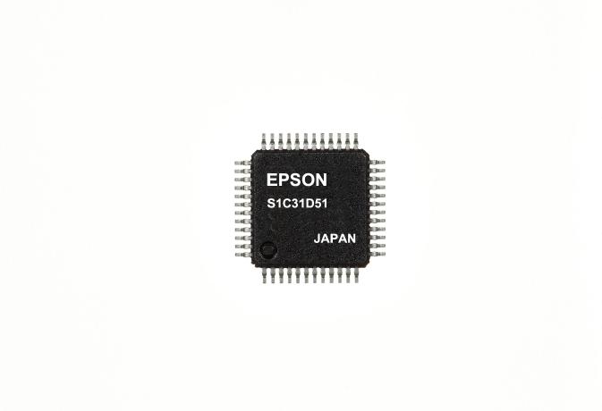
Epson has launched the S1C31D51, a 32-bit ARM Cortex-M0+ MCU that has integrated hardware that is able to play sound on speakers and buzzers. by Ally Winning @ eenewsembedded.com
Epson will manufacture 200,000 of the new controllers each month.
The ARM Cortex-M0+ processor features a dedicated hardware processor that is capable of producing 2-channel sound on the single MCU chip. This hardware allows the output of voice guidance sounds, such as error and warning messages on a buzzer instead of a speaker. Buzzer sound output performance can often be very poor with low volume and limited bandwidth. S1C31D51 improves that buzzer performance with a combination of software and hardware.
The dedicated “HW processor” support of the MCU allows two special features.
Initially, the HW processor plays the sound without the need for CPU resources, allowing those resources to be used by other processes – even during sound playback. Epson employs a high data compression algorithm (16 kbps @ 15.625 kHz) to cut the size of sound data memory. This makes it possible to use a large amount of sound data, or sound data in multiple languages. Epson’s also offers its own Voice Creation PC Tool. The software tool is free of charge for customers and provides a simple development environment to create sound data for 12 languages without studio recording. Existing WAV data can also be used.
Secondly, the MCU has an integrated self-memory check function that detects failures in built-in RAM, built-in Flash, and external QSPI-Flash memories without the use of CPU resources.
The 1 S1C31D51 evaluation board includes the TDK Corporation’s electromagnetic and piezoelectric buzzer. The board allows quick audio testing along with the preset demonstration.
The HW Processor dedicated hardware block executes a variety of functions without using CPU resources:
2-channel mixing sound (for playing background music + voice)
Voice speed conversion (playback speed adjustable in 5% increments between 75% and 125%)
A sampling rate of 15.625 kHz, which is high enough for background music as well as voice.
High-compression voice decoding algorithm with high sound quality (16/24/32/40 kbps)
Last time we examined how to program the STM8s microcontroller using the Arduino IDE. This way may work for developers who are familiar with the IDE and want to build quickly, and professional projects, but there are more ways to get the same result. Thus for today’s tutorial, we are going to examine how to use traditional tools like the Cosmic C compiler along with STVD to program the STM8s microcontrollers.
There are several members of the STM8s microcontroller out there but for this tutorial, we will work with the STM8S103F3P6 microcontroller which is one of the cheapest, and most popular member of the family. The popularity of the STM8S103F3P6 makes it a perfect microcontroller for beginners as you can easily find support for it across several forums on the internet.
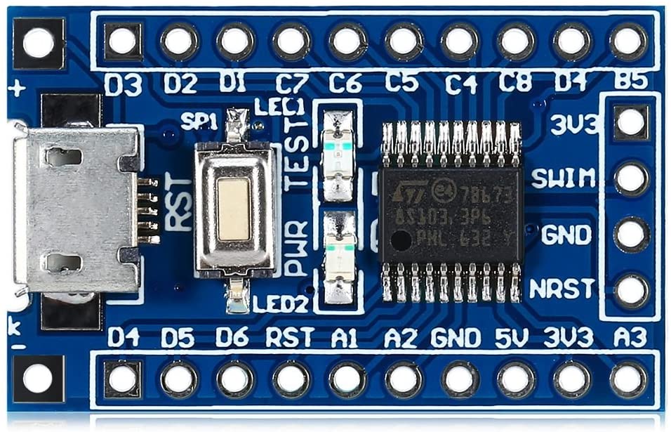
For easy prototyping, we will use the STM8sBlue development board which is essentially a breakout board for the STM8S103F3P6 MCU with a USB interface, breadboard compatibility, and a few other components to facilitate the development of prototypes for projects based on the MCU.
In addition to the STM8sBlue development board, we will need the ST-LINK programmer, preferably the ST-LINK v2 programmer. It will be used to upload firmware from the PC to the microcontroller.
Our goals for today’s tutorial will be to examine how to set up the tools, and for a demo, we will flash the microcontroller with the hardware hello world LED blink example.
Ready? Let’s go
Required Components
The components required to replicate and follow this project includes:
The STM8sBlue and the ST-Link programmer can be bought from the attached links, while others can be easily obtained from your favorite electronics component store. The resistor and LED are only important if you will prefer to use an LED other than the one onboard the STM8sBlue.
Schematics
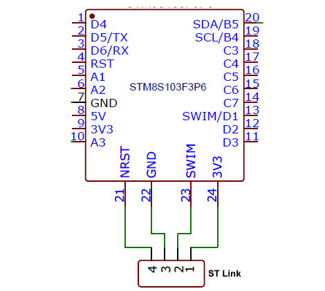
Asides schematics for folks who will not be using the onboard LED, the only schematics associated with this project is for the connection between the STM8sblue and the ST-Link V2 programmer. Connect both of them as shown in the schematics below:
Schematics
A pin-pin map showing how the ST-Link V2 is connected to the dev board is also provided below to make the connection easy to follow.
With this done, we can now proceed to set up the software side of the project.
Install the Cosmic C compiler and STVD
To program the microcontroller, we need an IDE and a compiler. As mentioned during the introduction, we will use the Cosmic C compiler and the ST Visual Develop (STVD) IDE. Unfortunately, both software is only available in the Windows OS version so you will need a windows based machine or a partition to install and use them.
Head over to Cosmic and ST websites and download the software. Both software is free to use and will only require you to sign up on the websites to download.
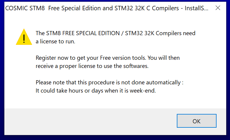
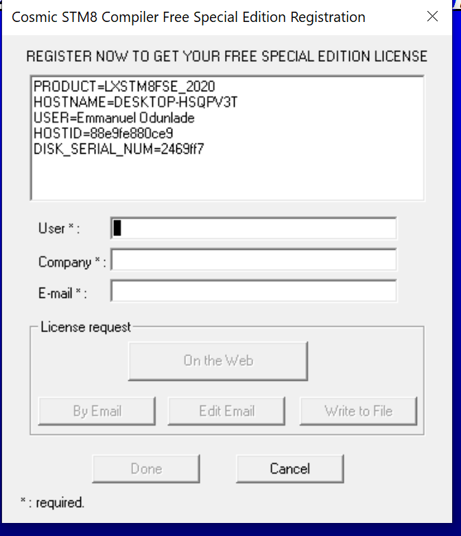
With both software downloaded, run the installation, following the on-screen instructions displayed by the setup wizard. The STVD IDE should install without a fuss, but the Cosmic C compiler will request that you get a free license key, with a prompt that asks for your email address.
The prompt is displayed after a readme file that contains guidelines on use, is closed.
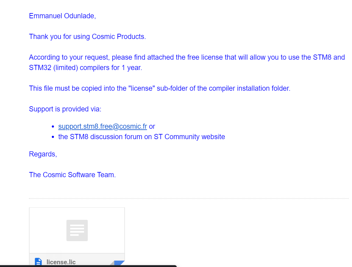
Fill the information requested by the prompt, select the “On the Web” option (if you are connected to the internet), and click on done. This should launch a webpage where you will be required to enter your email address again if not auto-filled. With these complete, you should get a license request processed notification, and receive the license key in your email, a few minutes after submitting the request. Due to spam algorithms, the license email may be “quarantined” in the spam section of your email box. Make sure also to check there.
With the license file received, follow the installation instruction, and copy the license.lic file to the “license” sub-folder of the COSMIC installation folder on your computer. In my case the license sub-folder was located at this path: “C:\Program Files (x86)\COSMIC\FSE_Compilers\CXSTM8\License“.
With this done, both software should now be fully installed and ready for use.
One other thing we need, that is probably better to also get at this stage, is the Standard Peripheral Library for the STM8S103F3P6 microcontroller. The library can be downloaded from ST’s website, but for simplicity and ease of use, this nicely modified library by Circuit Digest’s Aswinth Raj might be a better version.
With all these in place, we can now proceed to use these tools to develop the code for our project.
Code
To write the firmware, we need to create a new project specifying the microcontroller for which the firmware is to be developed and the destination folder where all project files will be store. Follow the steps below to do this:
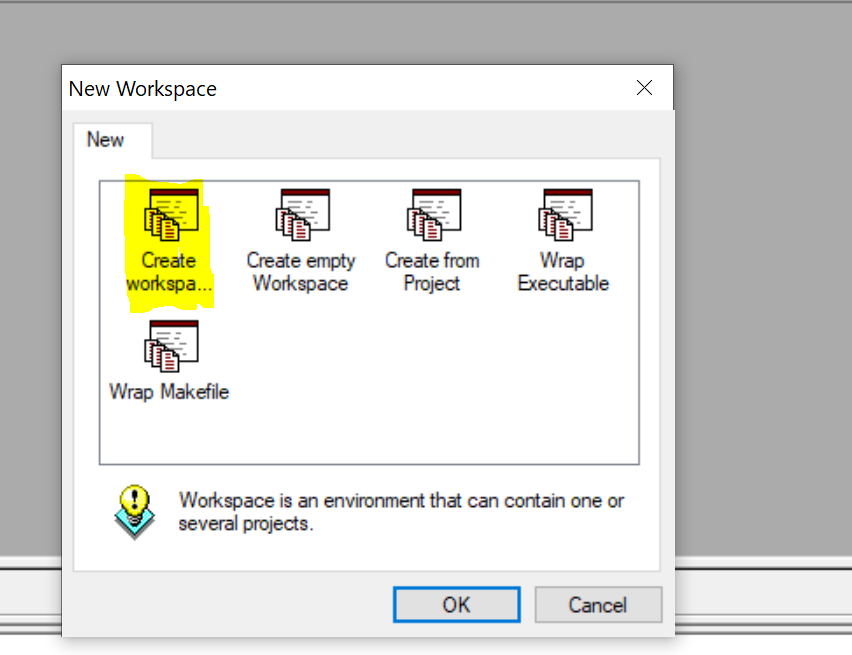
Start by opening STVD and select File -> WorkSpace, in the pop-up, select “New Workspace” and enter the Project name and path where the program should be saved. I am naming my program BareMinimum and saving it in a folder on the desktop. Click OK and you will get the New Project dialog box as shown below.
1. Open the Installed ST Visual Develop and go to File -> “New Workspace” to create a new workspace.
2. On the resulting pop-up box, select the “Create a Workspace and Project” option highlighted in the image below.
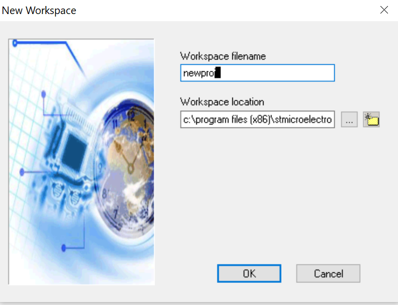
3. On the next window, enter your preferred workspace name. I will be calling this “newproj” and will save it in the default location. Click OK when done.
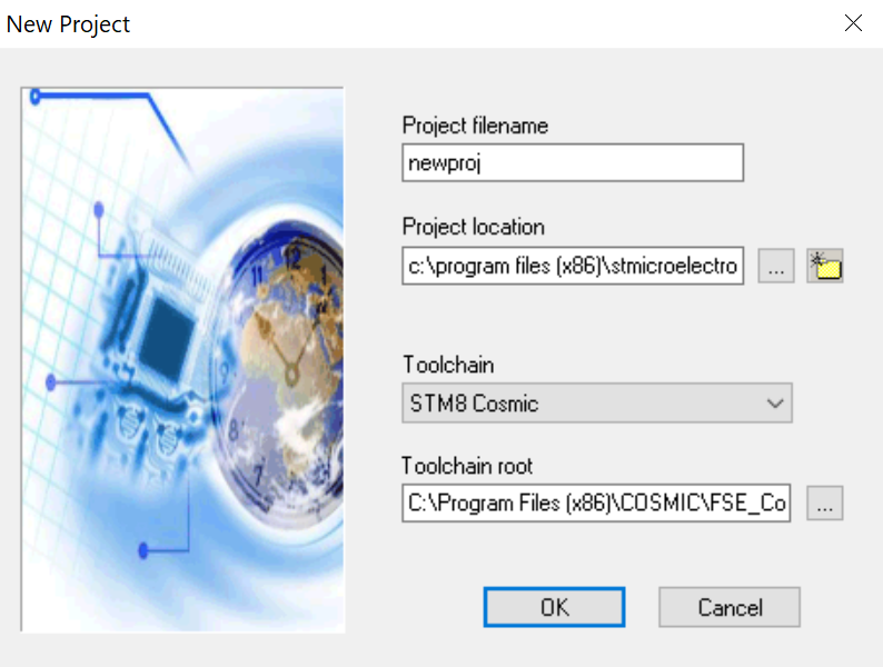
4. The next window will require you to provide a project filename, preferred storage location, the toolchain to be used, and the root address to the toolchain. For me, the project name will be newproj, and the directory will be the default. We will use the Cosmic C compiler so you should set the toolchain as STM8 Cosmic and the toolchain root should be the path where your Cosmic compiler was installed. The default path address is “C:\Program Files (x86)\COSMIC\FSE_Compilers\CXSTM8” and should also be the path on your machine if it was not changed during installation. You can also use the folder button to navigate to the CXSTM8 folder.
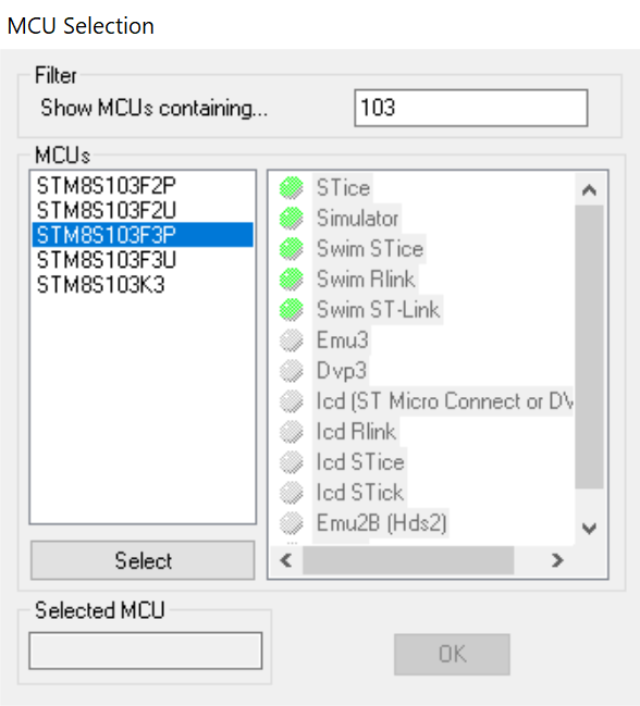
5. After clicking OK above, the MCU selection window will come up. Fill as shown in the image below, selecting the STM8s103F3P microcontroller.
You can quickly search for the microcontroller by typing its name in the search bar. With this done, click OK. You should now be able to see the STVD workspace.
6. Next, we need to add the SPL libraries we downloaded to the project files. To do this, expand the project folder (newproj) in the workspace, right-click on the “Source files” folder and click on the “add files to folder” option and navigate to the “src” folder in the library we downloaded. select all the “.c” files in the folder and add them.
7. Next, we need to also add the header files. Right-click on the “include files” folder on the workspace, and select “Add files to folder“. Navigate to the “inc” folder of the library we downloaded and add all the “.h” files.
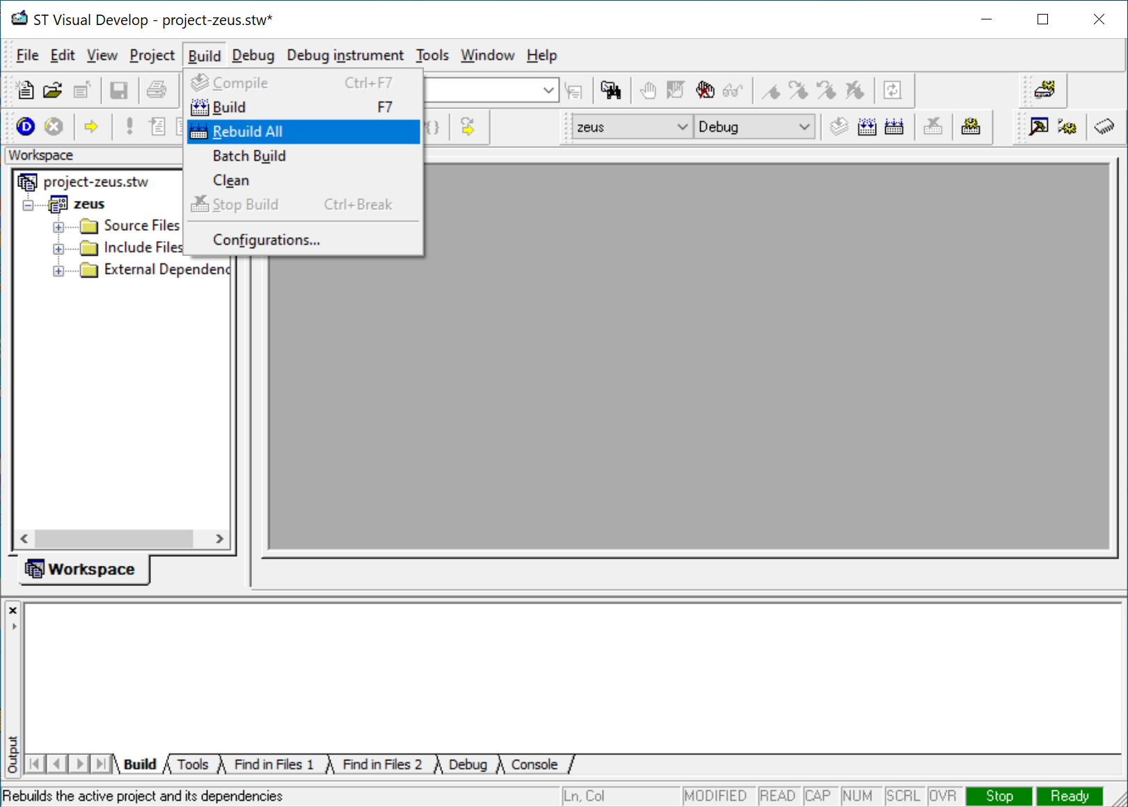
8. Verify library addition and general setup by building. Click on the “build” button and select “rebuild all” followed by the “compile” button.
If the build is successful, you should see “zero build errors” displayed on the command line like in the image below.
With this done you are now ready to start writing the code for our project.
As mentioned earlier, the code for today’s project will be to blink the onboard LED at certain intervals. As with all our projects, I will do a brief explanation of the code and provide the complete code at the end.
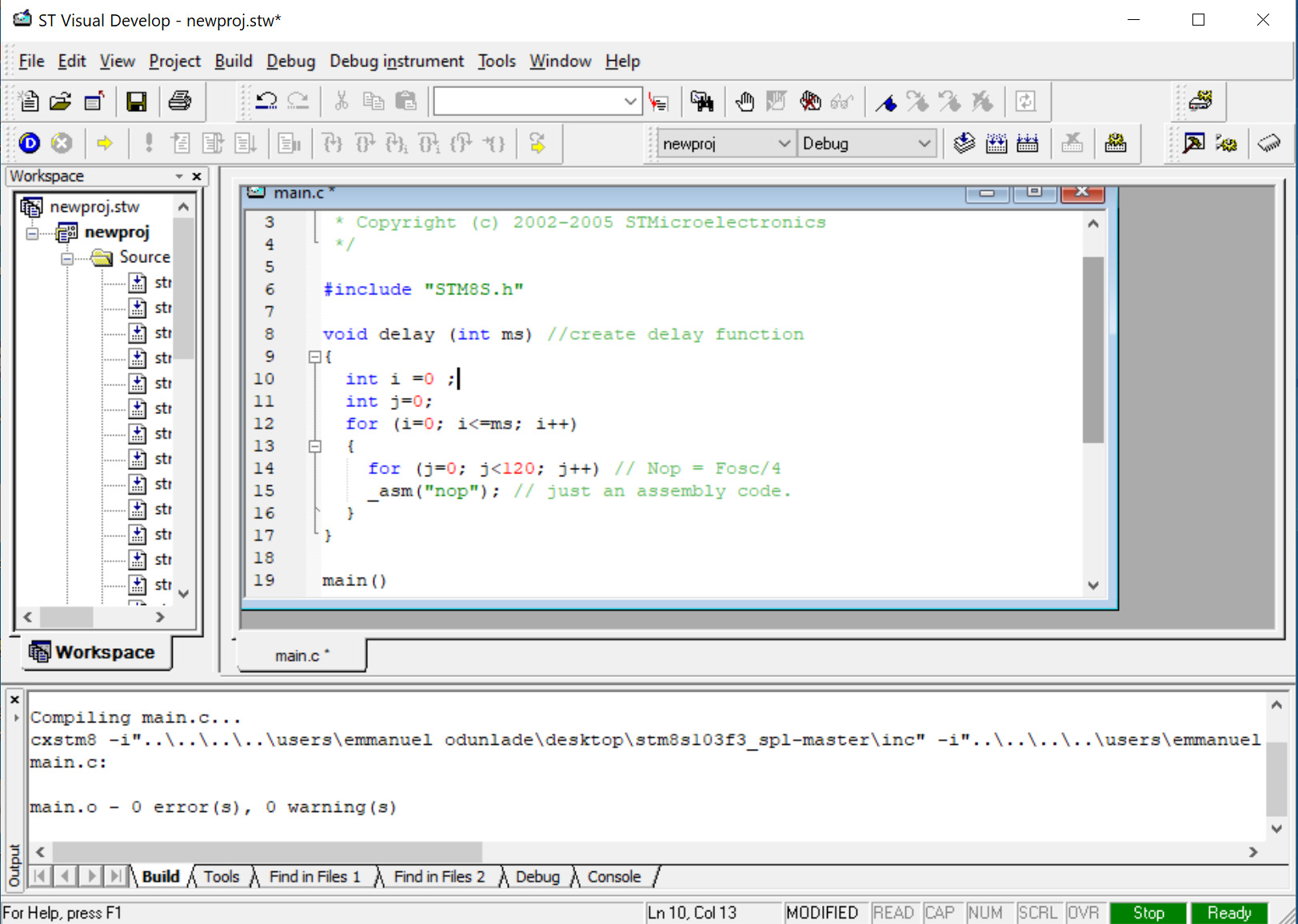
The code will be written in the main.c file which is automatically generated when you create a new project. We start the code by including the STM8s library, which helps adds some level of code IntelliSense to our project.
#include "STM8S.h"
Next, we write the delay function. Unlike with the Arduino where the functions are pre-written and we just call them to use, here you have to write most of the functions your self. The delay function will be used to indicate how long the led stays in a particular state before switching to the other state.
void delay (int ms) //create delay function
{
int i =0 ;
int j=0;
for (i=0; i<=ms; i++)
{
for (j=0; j<120; j++) // Nop = Fosc/4
_asm("nop"); //Perform no operation //assembly code <span style="white-space:pre"> </span>
}
}
Next, we write the main function. We start by deinitializing Port B, i.e., the port to which the pin of the onboard led is associated. While deinitializing the port is not mandatory, it helps totally free up the port from whatever function it was used for before, ensuring your project is hitch-free.
main()
{
GPIO_DeInit(GPIOB); // deinitialize port B
Next, we declare the pin to which the onboard led is connected as a push-pull output pin with default low status.
Finally, we write the while loop function. Here we basically place the code to turn ON and OFF the onboard led. For this, we will use the GPIO_WriteReverse() function which reverses the state of the pin. So if it was on before, it turns it OFF, and vice versa. We will also add a delay of 200ms to allow us to see the blink without the eye’s persistence effect.
while (1)
{
GPIO_WriteReverse(GPIOB,GPIO_PIN_5);
delay (200);
}
}
The complete code for the project is provided below;
/* MAIN.C file
 *
 * Copyright (c) 2002-2005 STMicroelectronics
 */

#include "STM8S.h"

void delay (int ms) //create delay function
{
  int i =0 ;
  int j=0;
  for (i=0; i<=ms; i++)
  {
    for (j=0; j<120; j++) // Nop = Fosc/4
    _asm("nop"); // just an assembly code.
  }
}

main()
{
  GPIO_DeInit(GPIOB); // deinitialize port B

  GPIO_Init (GPIOB, GPIO_PIN_5, GPIO_MODE_OUT_PP_LOW_SLOW);
  //Declare PB5 as a default low push-pull output pin

  while (1);
  {
    GPIO_WriteReverse(GPIOB,GPIO_PIN_5);
    delay (100);
  }
}
Uploading the Code
With the code complete, its time to hook up your board to your computer and upload the code. The process of uploading code to the board is not as straight forward as with the Arduino IDE but its easy to follow and should become seamless once you get the hang of it.
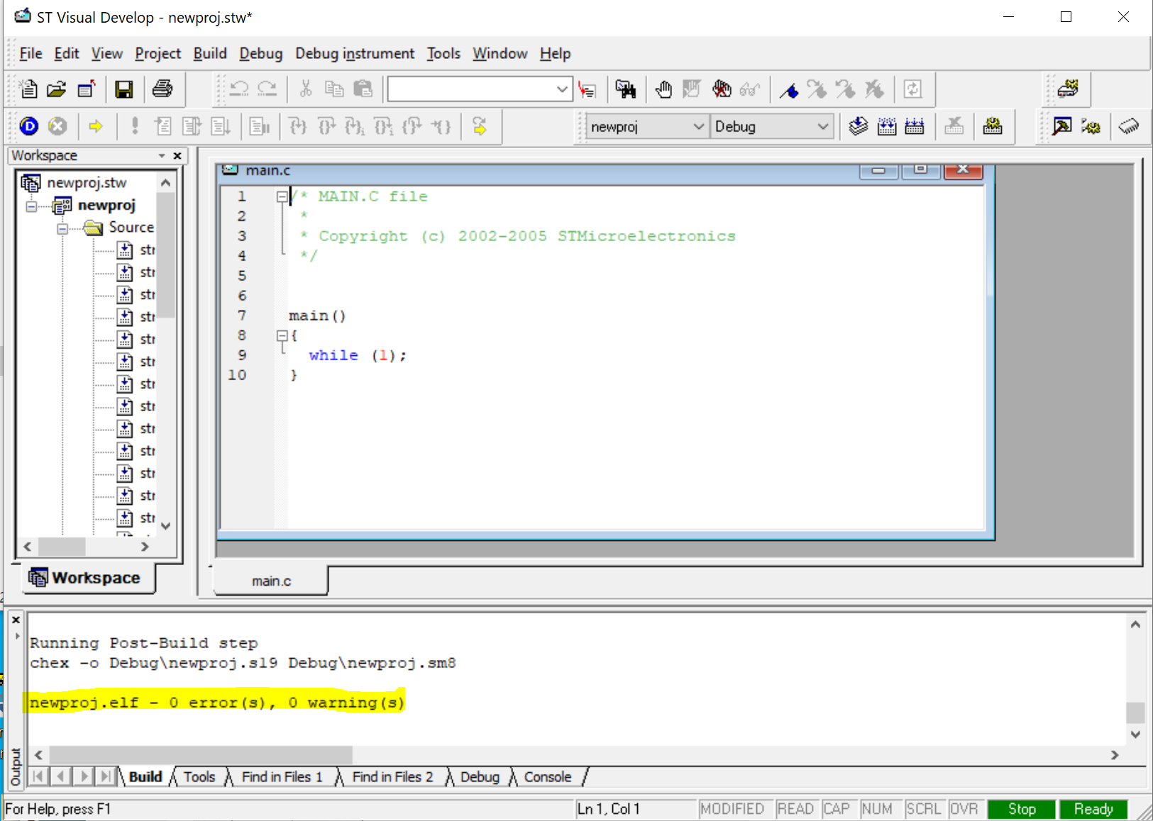
Once the code is complete, click on the Build -> rebuild all and ensure there are no errors. If everything is fine, it should return the “0 errors and o warnings” line. With this done, hit the Compile button. If there are no errors, the program should compile easily and you should see the “0 errors and 0 warnings” in compile success line.
With the successful compiling, a “.s19” file will be generated under the debug directory of the project’s folder. This file is similar to the Hex file and it’s what you will upload to the microcontroller. To upload the .s19 file to the microcontroller we will use the ST Visual Programmer (STVP) which would have been installed alongside STVD.
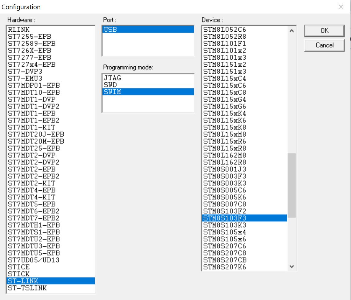
When opened, the STVP presents the configuration page shown below. Select the programmer, the programming mode, and the device/microcontroller which in this case are ST-Link, SWIM, and STM8s103F3 respectively.
Hit the OK button when complete. This should launch the STVP interface.
Click on “file->Open” and navigate to the debug folder where you have the .s19 file we generated earlier and open it. Click on “Program”and select “Current Tab“. These should begin the flashing process and the firmware should now be loaded on your microcontroller. If successful, you should see the following line on the command prompt area of the software:
and the LED on the STM8sblue should also start blinking at a pace equal to the 200ms we specified.
It is probably important to note that before launching the STVP, you should connect the microcontroller via the ST-link to your computer. If you are using the ST-Link for the first time, the device driver will automatically be installed on your PC. If this is not the case you might need to run a quick google search to find out the requirements for your computer.
That’s it, folks! There you have it. If you have any challenges with any part of the project, do reach out to me via the comment section. I will be happy to help.
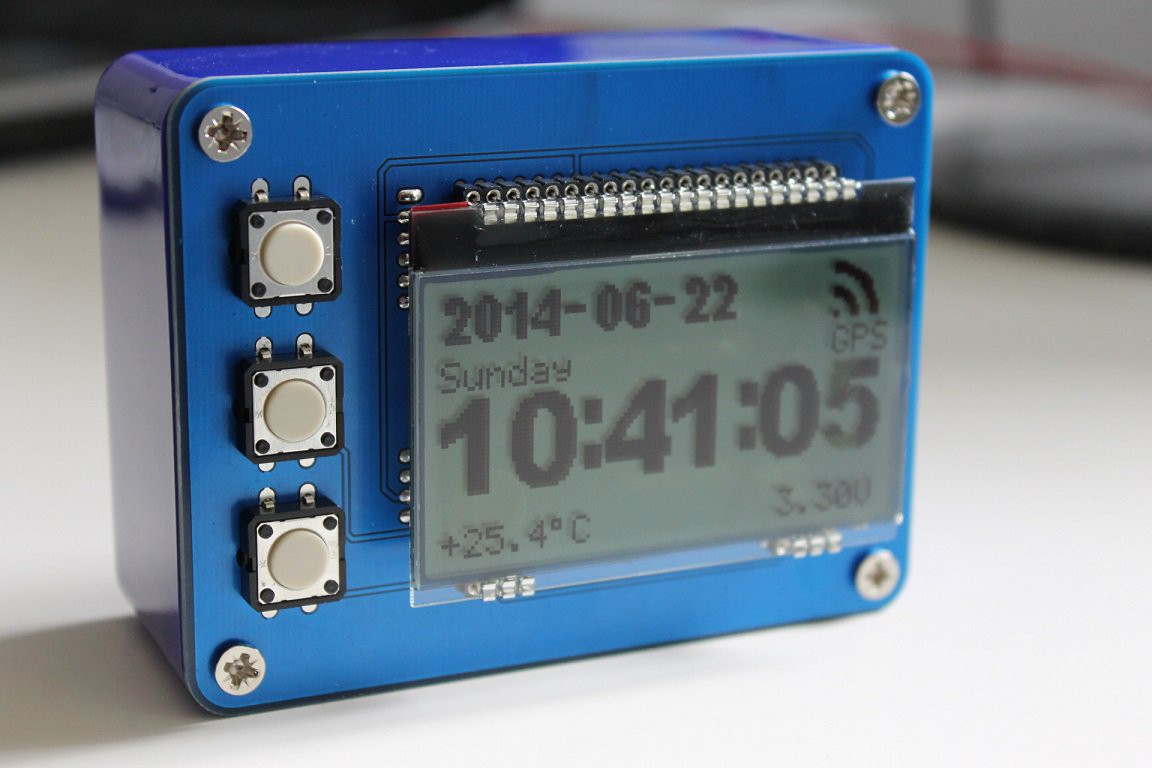
This project is a clock with radio receivers that can receive the exact time from the GPS satellites or from the DCF77 transmitter. by hkdcsf @ hackaday.io
This project is a clock with radio receivers which can receive the exact date and time from the DCF77 time signal transmitter or the UTC from the GPS satellites and display it on a 128×64 pixel graphic display. DCF77 transmitter and GPS is synchronized to an atomic clock. So basically this project can “connect to” an atomic clock.
“Connect” to an atomic clock in space! GPS, DCF77 – [Link]
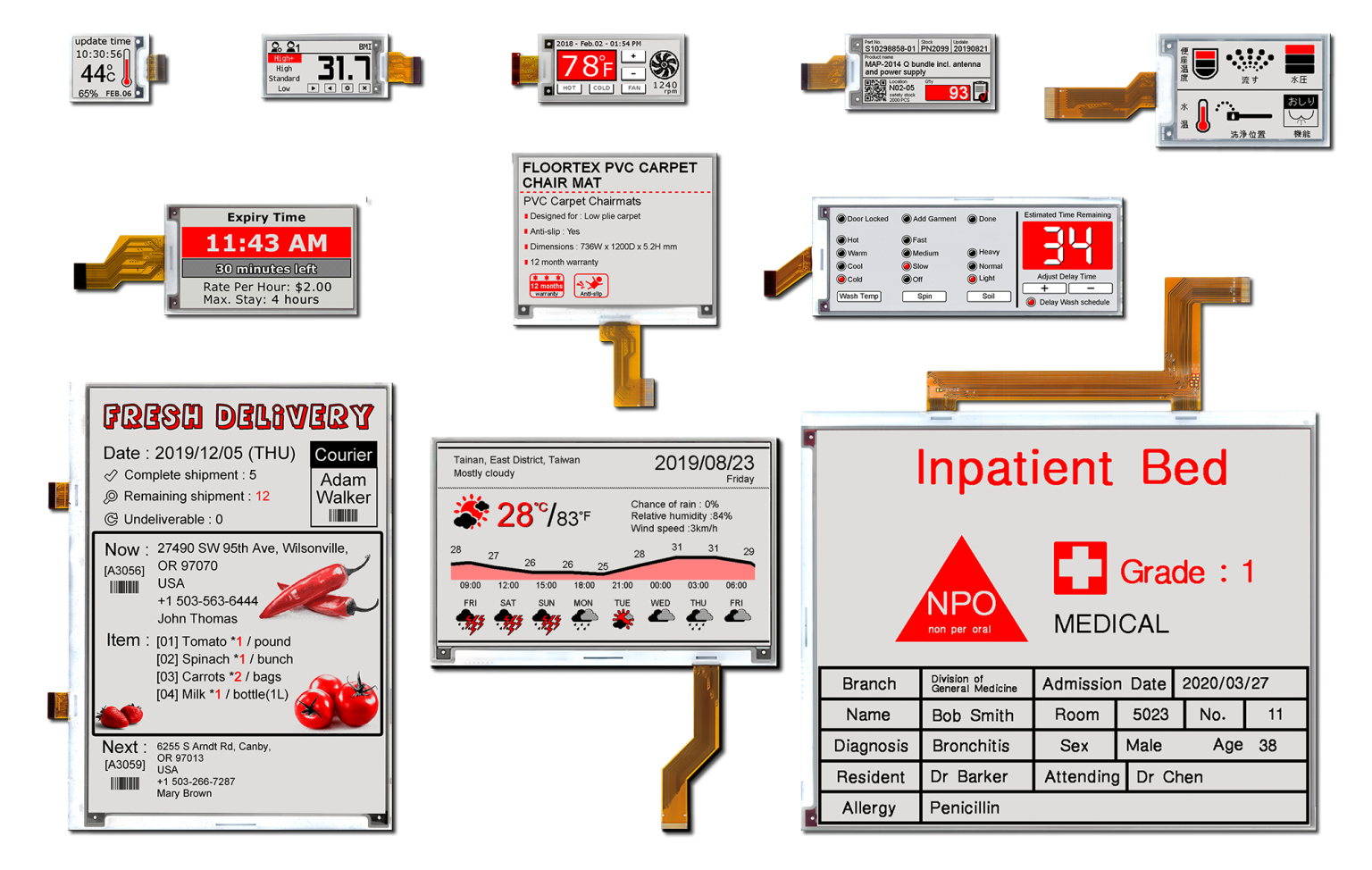
Pervasive Displays (PDi) has announced a new wide operating temperature range for its Spectra e-paper displays (EPDs). The Spectra range comprises 12 EPD modules with size options from 1.54 to 12.2”.
These small, low power, active-matrix EPDs can now operate from zero to +40°C (10°C lower than before) making them suitable for most indoor and many outdoor operating conditions.
EPDs are bistable, meaning that they require no power to display an image and use very little power to update the screen. The one time programmable (OTP) feature of each EPD module operates alongside the internal timing controller (iTC) to store an image waveform inside the display driver. As there is no requirement for the host processor to load an image at startup, the time to the first image is reduced, improving the user experience.
Alchin Wang, General Manager, Pervasive Displays, said:
“We’ve increased the lower end of the operating range of our Spectra EPDs down to zero from 10°C. As the uppermost temperature they are capable of operating in is +40°C, these low power screens are now a great option for a variety of applications where reliability is paramount such as in cold chain, healthcare and warehouse setting.
“And, as these EPDs all benefit from iTCs, we can offer customers a product which is smaller and lighter, saving them space on the PCB and reducing the bill of materials.”
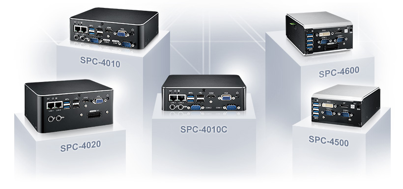
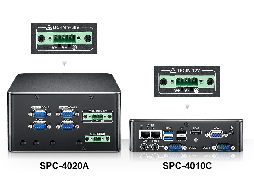
Vecow Co., Ltd., a team of global embedded experts, are pleased to introduce the latest SPC-4010C, a new member of the popularly sold SPC-4000 Series Ultra-compact Fanless Embedded Box PC that is based on Intel Atom® (Apollo Lake) processor. Vecow SPC-4010C is powered by dual-core Intel Atom® x5-E3930 processor, outfitted with dual display port supporting up to 4K resolution, 2 GigE LAN, 2 COM and featuring -40°C to 75°C extending temperature. Given the exceptional combination of energy-efficiency and flexible expansion functionality, SPC-4010C is an ideal solution for Machine Vision, Robot Control, Infotainment System, Factory Automation, Intelligent Control or any compact AIoT or industrial 4.0 embedded applications.
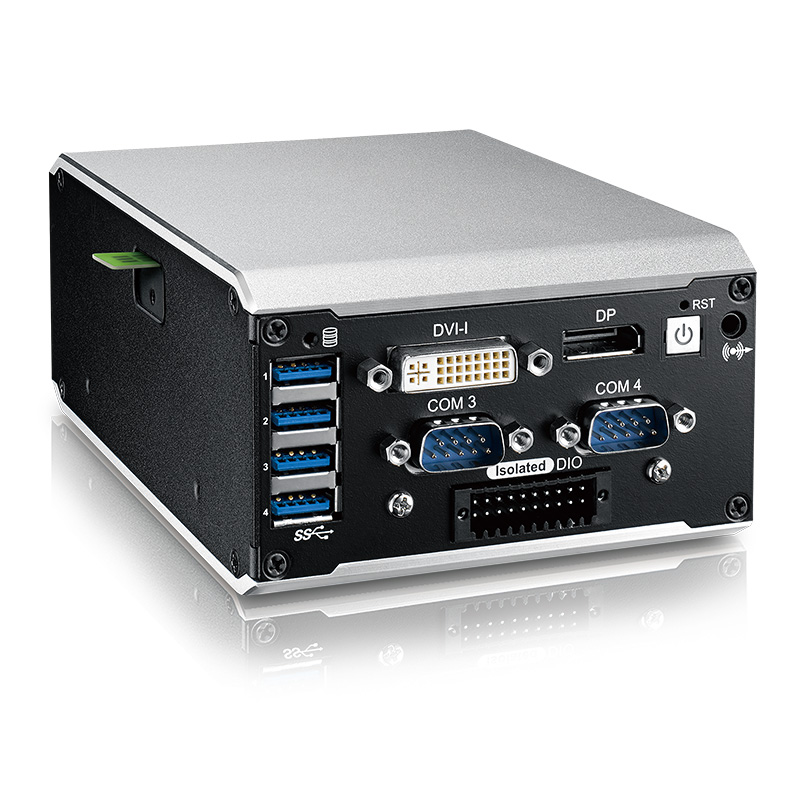
Vecow’s extension of the SPC-4000 Series Ultra-compact Fanless Embedded Box PC runs on quad-core/dual-core Intel Atom® SoC (Apollo Lake-I). It is industry-proven, has excellent energy-efficiency, features Intel® Time Coordinated Computing (TCC) Technology and allows systems operating in synchronization and improving network accuracy. Paired with the Intel® HD graphics 505/500, SPC-4000 Series’s lockable HDMI and VGA or DVI-I and DisplayPort deliver up to 4K ultra HD resolution, supporting DirectX 12 API. With performance boost for graphics and CPU performance over the prior generation of quad-core Atom processor, SPC-4000 Series is a perfect solution for both graphics-intensive and performance-driven embedded applications.
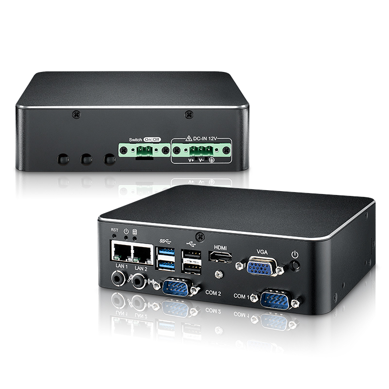
Vecow SPC-4000 Series provides versatile interfaces to empower a wide range of applications, which includes lockable HDMI and VGA or DVI-I and DisplayPorts, 2 GigE LAN with IEEE 802.3at PoE+ LAN supporting IEEE 1588 (PTP), 1 SATA III socket, 1 2.5″ SSD bracket, 6 USB, 1 SIM socket, 16 Isolated DIO, 4 COM RS-232/422/485 with 2 isolated. To fulfil industrial-grade requirements, Vecow SPC-4000 Series offers an extended operating temperature (-40°C to 75°C) and supports ignition power control, 12V power input, optional wide-range power input of 9V to 36V, compliant with EN50155, EN50121-3-2. The fanless ultra-compact SPC-4000 Series delivers compact solutions through system-oriented integration.
“Vecow new extension of SPC-4000 Series provides synergy between low power consumption and rich I/O expansion, enabling our customers to fulfil space constrained applications.” said Shally Tsou, Product Manager, Embedded System & Platform Division, Vecow. It’s worth mentioning that SPC-4000 also includes versatile expansion options for easy configuration. Mini PCIe, M.2 key B socket and 4 antenna holes to accommodate a variety of LTE, 3G, WIFI and GPS modules to bring more possibilities and flexibilities for your compact embedded solutions.”
“I am so excited to include the ultra-compact embedded box PC in my offering list,” said Joseph Huang, Sales Manager, Sales & Marketing Division at Vecow. “The core idea of SPC-4000 Series is to dedicatedly reach into flexible configurations with rich I/O interfaces and power-efficient markets, addressing the requirements for space-critical, AIoT-oriented solutions.”
With Intel Atom® x7-E3950/x5-E3930 processor (Apollo Lake-I), offering excellent energy-efficiency, compact solution, rugged reliability and system-oriented integration, coming with smart manageability and mobile availability features, SPC-4000 Series Ultra-compact Fanless Embedded Box PC is your great choice for Machine Vision, Robotic Control, Infotainment System, Factory Automation, Intelligent Control and any AIoT or Industry 4.0 applications.
Intel Atom® x7-E3950 SoC (Apollo Lake-I) Ultra-compact Fanless Embedded Box PC, lockable HDMI and VGA dual display, 2 GigE LAN support IEEE 1588 (PTP), 4 COM with 2 Isolated, 16 Isolated DIO, 4 USB, 1 SIM, 12V DC power input, low power consumption, Fanless -40°C to 75°C operating temperature
Intel Atom® x7-E3950 SoC (Apollo Lake-I) Ultra-compact Fanless Embedded Box PC, lockable HDMI and VGA dual display, 2 GigE LAN support IEEE 1588 (PTP), 4 COM with 2 Isolated, 16 Isolated DIO, 4 USB, 1 SIM, 9V to 36V wide range DC power input, low power consumption, Fanless -40°C to 5°C operating temperature
Intel Atom® x7-E3950 SoC (Apollo Lake-I) Ultra-compact Fanless Embedded Box PC, DVI-I and DisplayPort dual display, 2 GigE LAN support IEEE 1588 (PTP), 4 COM, 4 USB 3.0, 1 external SIM, 12V DC power input, low power consumption, Fanless -40°C to 85°C operating temperature
Intel Atom® x7-E3950 SoC (Apollo Lake-I) Ultra-compact Fanless PoE+ Embedded Box PC, DVI-I and DisplayPort dual display, 2 PoE+ GigE LAN support IEEE 1588 (PTP), 4 COM, 16 Isolated DIO, 4 USB 3.0, 1 external SIM, 9V to 36V wide range DC power input, Ignition Power Control, low power consumption, Fanless -40°C to 75°C operating temperature.
To know more about SPC-4000 Series Ultra-compact Fanless Embedded Box PC, please visitSPC-4000 product page or www.vecow.com for more details.
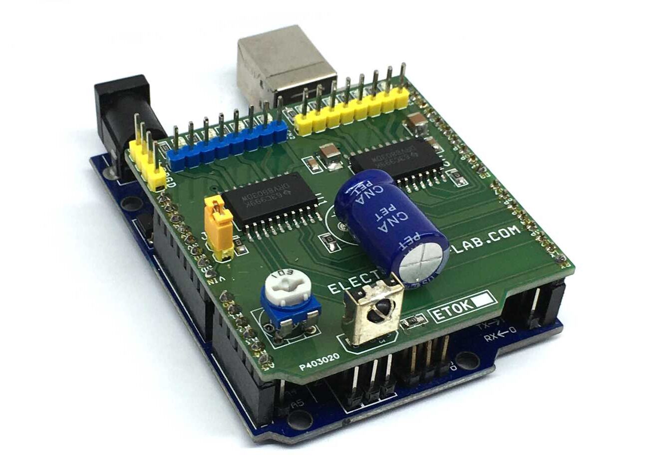
The 8 Channel Driver Arduino UNO Shield is designed to enable users to switch inductive loads for up to 800mA each channel and up to 24V DC with no heat-sink needed. It is ideal for such applications as driving 2x unipolar stepper motors, solenoids, relays, and small DC motors. It uses 2x DRV8803 Chip from Texas instruments which is 4 channel low side driver with over current protection. IC’s Internal shutdown protection function is provided for overcurrent protection, short circuit protection, under-voltage lockout, and over temperature. Faults are indicated by a fault output pin that is normally high and goes low if a fault condition occurs. Reset and enable pins has internal pull-down resistors.
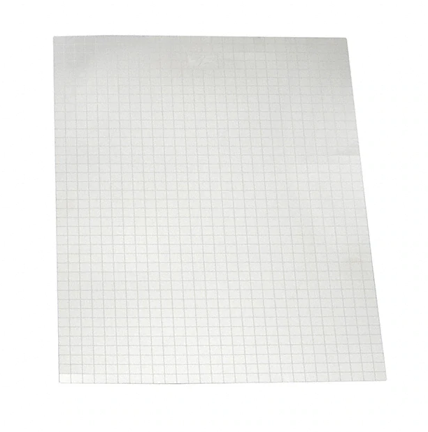
Würth Elektronik’s ShielDIY kit is a fast prototyping solution for board-level shielding cabinets
Würth Elektronik has created a do-it-yourself custom shielding cabinet kit, the ShielDIY. The ShielDIY kit is a fast prototyping solution for board level shielding cabinets. The kit is made up of nickel silver sheet with a thickness of 0.2 mm. The sheets feature lines carved every 5 mm for easy bending and cutting. To build a prototype, cut along the carved lines before bending to obtain the desired shape.
Features
Do-it-yourself shielding cabinet; users can create a custom cabinet with this kit
Shape board-level shielding
Foldable and cuttable with carved lines every 5 mm
Material is nickel silver with the same performance as the tinplated steel used in the standard cabinets
Useful for fast prototyping
Applications
Preventing EMI radiation from PCB and keeping sensitivity low
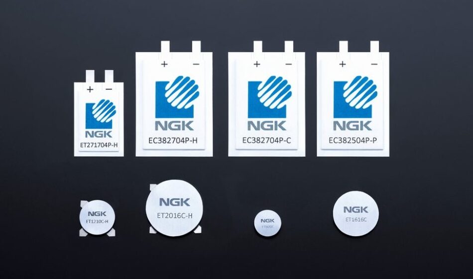
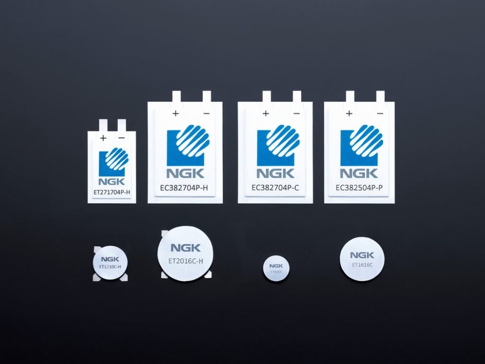
The new battery is scheduled for mass production in September 2020, with potential applications primarily in automotive and industrial IoT devices.
NGK INSULATORS, LTD. (hereinafter “NGK”) has successfully raised the maximum operating temperature of its coin-type “EnerCera Coin” (part of the “EnerCera®” series) battery up to 105 degrees Celsius. Sample shipments are currently underway, with mass production scheduled to begin in September 2020.
In December 2019, NGK developed the world’s first lithium-ion rechargeable battery which has achieved an operating temperature range of -40 to +85 degrees Celsius. As a result of improvements to the product based on customer feedback, NGK recently succeeded in increasing the upper limit of the operating temperature by 20 degrees. The battery is now capable to be used at an operating temperature of up to 105 degrees Celsius, while still maintaining capacity and power. In its fully charged state, when the battery is most prone to deterioration, the capacity decrease is less than 20% even after it is kept at 105 degrees for 1000 hours.
NGK’s EnerCera Coin battery has a unique structure in which a small amount of electrolyte is added to its all-ceramic stacked monolithic body with electrodes and a separator. This provides high thermal stability. The EnerCera battery is categorized as semi-solid-state battery, with performance equivalent to or better than that of a conventional lithium-ion rechargeable battery. The EnerCera battery’s excellent heat resistance characteristics are comparable to those of all-solid-state batteries.
In addition, EnerCera Coin offers flexibility in installation. It can be mounted on a circuit board by reflow soldering, which is a common method for mounting electronic components on board. Furthermore, the battery can also be mounted through injection molding, where molten resin with temperatures of up to 300 degrees is poured into the mold and the battery directly embedded into the resin structure. This allows for the realization of an electronic device with unprecedented design and robustness.
With regard to the latest technological improvements, Iwao Ohwada, Vice President at NGK commented that the:
“development of high heat resistance products was realized through feedback from various partners in the automotive, industrial, logistics and smart card industries. We will continue to work closely with our partners to develop innovative solutions that accelerate the spread of IoT solutions.”
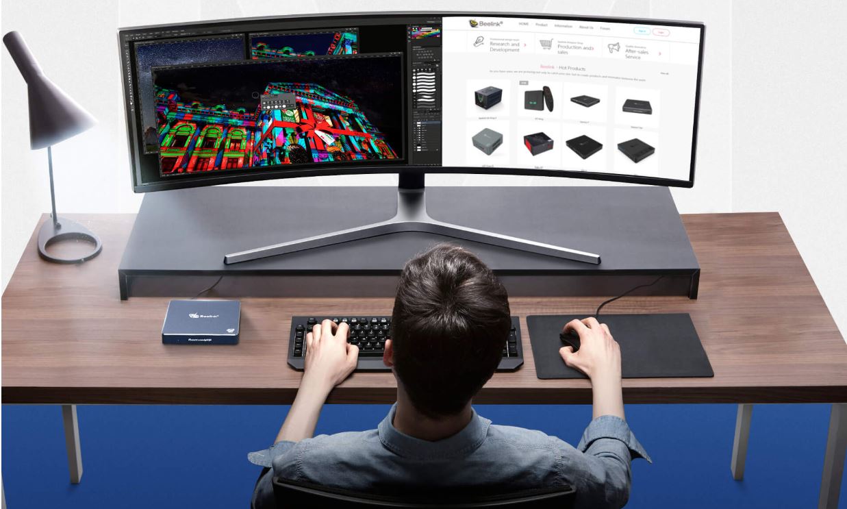
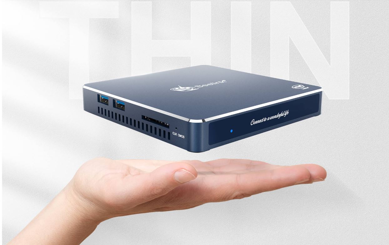
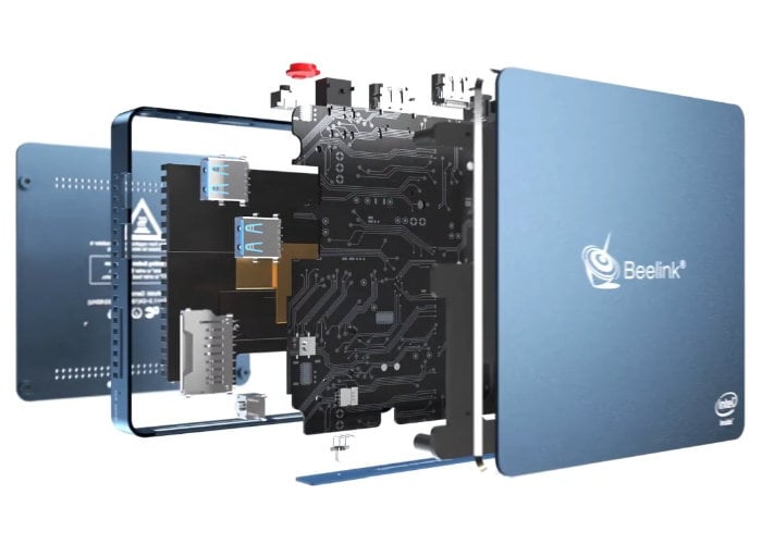
Shenzhen based computer hardware manufacturer, Beelink, recently teased the release of a series of new Mini PCs top of which was the Beelink Gemini M, an ultra-thin Mini PC powered by the Intel Celeron J4125 processor running with 8GB of RAM.
Featuring an ultra-thin aluminum enclosure and chassis, designed in a manner that allows for use in a variety of applications, the unique 1.77 cm thinness, 340 grams weight, 11.9cm reduced side size, and Vesa support possessed by the Beelink Gemini M, allows easy integration across different platforms including installations behind a monitor.
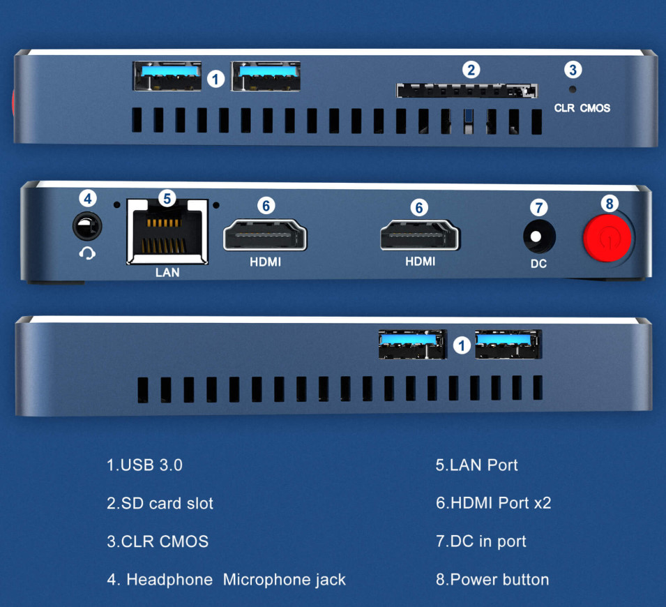
Giving users all that they might expect from a full-blown PC, the Beelink Gemini M comes with an assorted number of ports; including 4 USB 3.0 ports, an SDXC card reader, two HDMI 1.4 outputs to drive two displays in parallel in UltraHD, a 3.5 mm audio jack port with combined headphone and microphone, and a Gigabit Ethernet port.
In terms of processing power, the dual-core Intel Celeron J4125 processor being used on the new Mini PC is a member of the recently released Intel Gemini Lake Refresh (GLK-R) family of processors, which are upgraded versions of Intel’s desktop chips, running in a 10 watt PDT (Compared to 6 watts for the Celeron N4100), offering a level of overall performance that positions the Beelink Gemini M in the top category of high performing desktop mini PCs.
The Processor, running at a 2 to 2.7GHz speed, comes with 8GB of RAM, 4MB of cache memory, a 64GB eMMC, and an M.2 SATA 3.0 storage ranging from 128 to 512GB in 2242 format. While the specs so far do not reveal the capacity of the device for a high-quality gaming experience, the device thus comes with an Intel UHD 600 graphics card running at 250 to 700 MHz, capable of decompressing video in UltraHD H.265.
For communications/connectivity, the Beelink Gemini M comes with a Gigabit Ethernet port, a dual-band 802.11b/g/n/ac WiFi 5, and Bluetooth 4.0 all powered by an Intel 3165 wireless card.
Highlight features of the device include:
CPU – Intel Celeron J4125, 4 Cores 4 Threads 2.0Ghz, up to 2.7Ghz, Cache 4M
GPU – Intel® HD Graphics 600
Memory – 8GB RAM LPDDR4
Storage – 64GB eMMC or 128GB SSD mSATA + SATA SSD 2242, SD card
Video Output – 2x HDMI ports Audio – Via HDMI, 3.5mm audio jack
Connectivity – Gigabit Ethernet 1000Mbps, Dual-Band 802.11a/b/g/n/ac WiFi, Bluetooth 4.0
USB – 4x USB 3.0 ports
Misc – Power button, Fan and heat sink, mounting on the back of the monitor
Power Supply – 12V 1.5A
Power Consumption – Standby: 0.5W; typical: 12W
Dimensions – 11.90 x 11.90 x 1.77 cm
Weight – 340 grams
Other PCs being teased include a Beelink GT-R and the GT-R AMD which are both expected to come with WiFi 6 amongst other features.
There is currently no information on the Price and availability of the Mini PC but all indications show that the device could be launched before the end of Q3 2020 with a price range of around $200.
More information on the Mini PC can be found on its Product Page.