AR18/AR35 Series Single-Turn Absolute Encoders

Broadcom’s AR18 and AR35 series miniature programmable single-turn absolute encoders with resolution ranging from 17-bits to 21-bits

Broadcom’s AR18 and AR35 series are the miniature absolute encoder ASICs designed to cater to the growing demand for space-constrained applications. The AR18 encoder is designed for an overall diameter of 18 mm and offers user-programmable resolution ranging from 17-bit, 19-bit, and 21-bit single-turn absolute output. The AR35 encoder is designed for an overall diameter of 35 mm and offers 17-bit and 21-bit single-turn absolute output. Both the AR18 and AR35 series provide the incremental ABI and UVW in differential mode. Both come with a recommended temperature range of -40°C to +115°C suitable for most industrial applications. Dual-mode operating voltages of 3.3 V and 5 V enable handheld and portable device applications.

Features
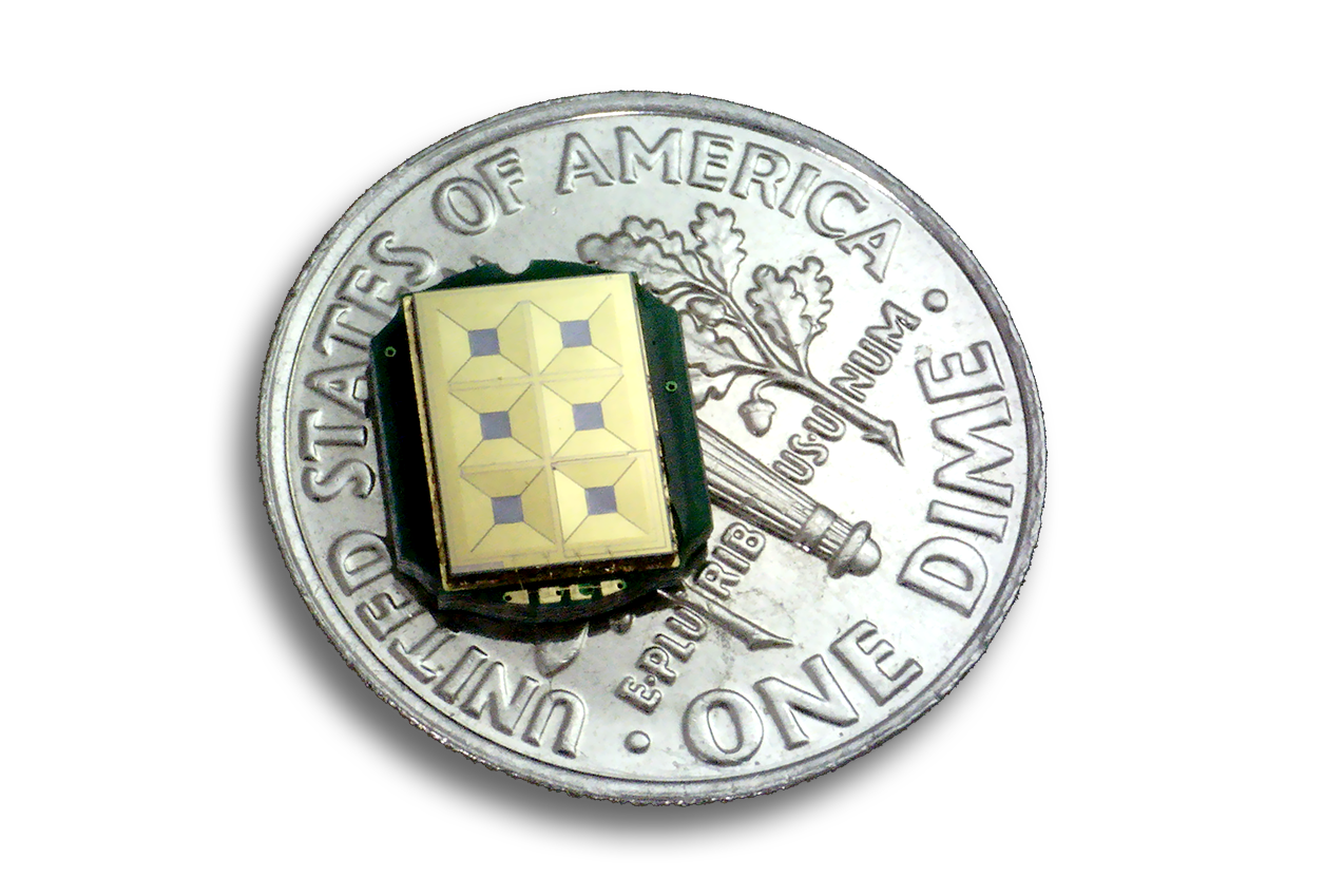
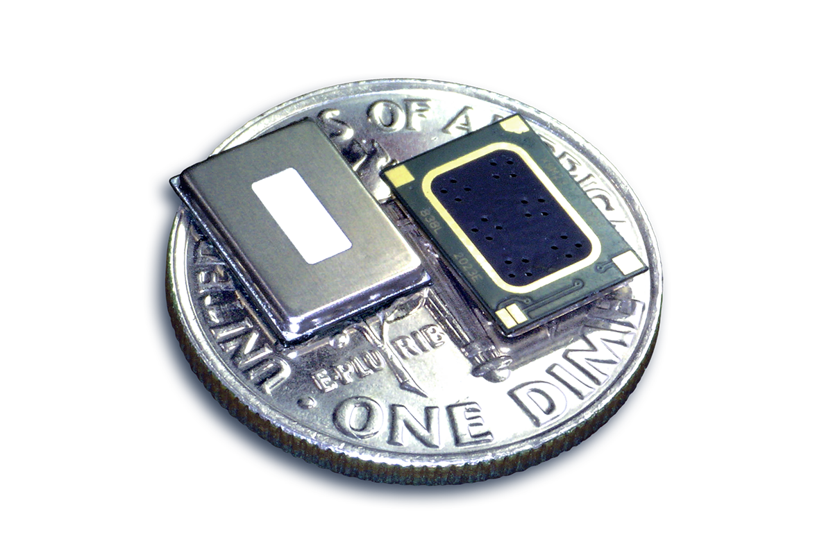
  • Miniature absolute encoder ASIC surface mount DFN package: 10.9 mm (L) x 9.1 mm (W) x 1.5 mm (H)
  • User-programmable resolution ranging from:
    • 17-bit, 19-bit, and 21-bit single turn (OD18)
    • 17-bit and 21-bit single turn (OD35)
  • User-programmable incremental output (ABI) resolution ranging from 128 CPR to 8192 CPR
  • Selectable SSI mode communication protocol
  • RoHS-compliant
  • User-programmable commutation signal (UVW) in 2-pole, 3-pole, 4-pole, 5-pole, 12-pole, 30-pole, 32-pole pairs
  • Differential output for ABI and UVW
  • High temperature range of -40°C to +115°C suitable for most of the industrial operation
  • Dual-mode operating voltage of 3.3 V and 5 V, enabling handheld and portable device applications
  • Selectable RS485 mode communication protocol

more information: www.broadcom.com

Compact Low-Power Mini Graphic LCD

DISPLAY VISIONSEA-DOGS102 series graphic LCDs are available in an FSTN positive transflective, STN negative transmissive, and FSTN positive reflective version. These displays have a 2.54 mm pitch and can be soldered directly or plugged into socket strips. Therefore, cumbersome gluing procedures, the need for designing a special mounting device, and error-prone cable connections that may lose contact are no longer a concern.

This LCD family was designed for use in the German industry and will have an availability of 15+ years. The extremely efficient ratio of external dimensions to the active display area helps in designing very compact devices. Furthermore, its low-power use [single supply 2.5 V to 3.3 V (typically 250 µA)] makes it ideal for handheld applications.

The EA 9780-4USB development board and free windows simulator are all users require to evaluate pin connected chip-on-glass LCDs with and without backlight. Simply plug the 2.54 mm connector pins of the display into the socket strips of the development board. Proprietary hardware or software development is not required. Decisions can be made quickly at a minimum expense.

Resources

  • Download the free EA LCD Simulator Software
    • Plug the display into the EA 9780-4USB development board
    • Connect the EA 9780-4USB development board to PC using the USB cable
    • Write text or select graphics, the display will show the content
  • Video: Industrial LCD Display Simulator

Features

  • High-contrast LCD supertwist display (STN and FSTN) with 10 µm dot gap
  • FSTN pos. transflective, STN neg. transmissive, and FSTN pos. reflective version (cannot be backlit)
  • Optional LED backlights in various colors; white, amber, green/red, and customs
  • 102 x 64 pixels (corresponds to 8 x 17 characters or 4 x 12 large characters)
  • UC1701 controller with SPI (4-wire) interface
  • Power supply: single supply 2.5 V to 3.3 V (typ. 250 µA)
  • No additional voltages required
  • Operating temperature range: -20°C to +70°C (storage -30°C to +80°C)
  • No mounting required, simply solder onto PCB

more information: https://www.lcd-module.com/eng/pdf/grafik/dogs102-6e.pdf

Rigol RSA3000N/5000N Real Time Spectrum Analyzers with Vector Network Analysis

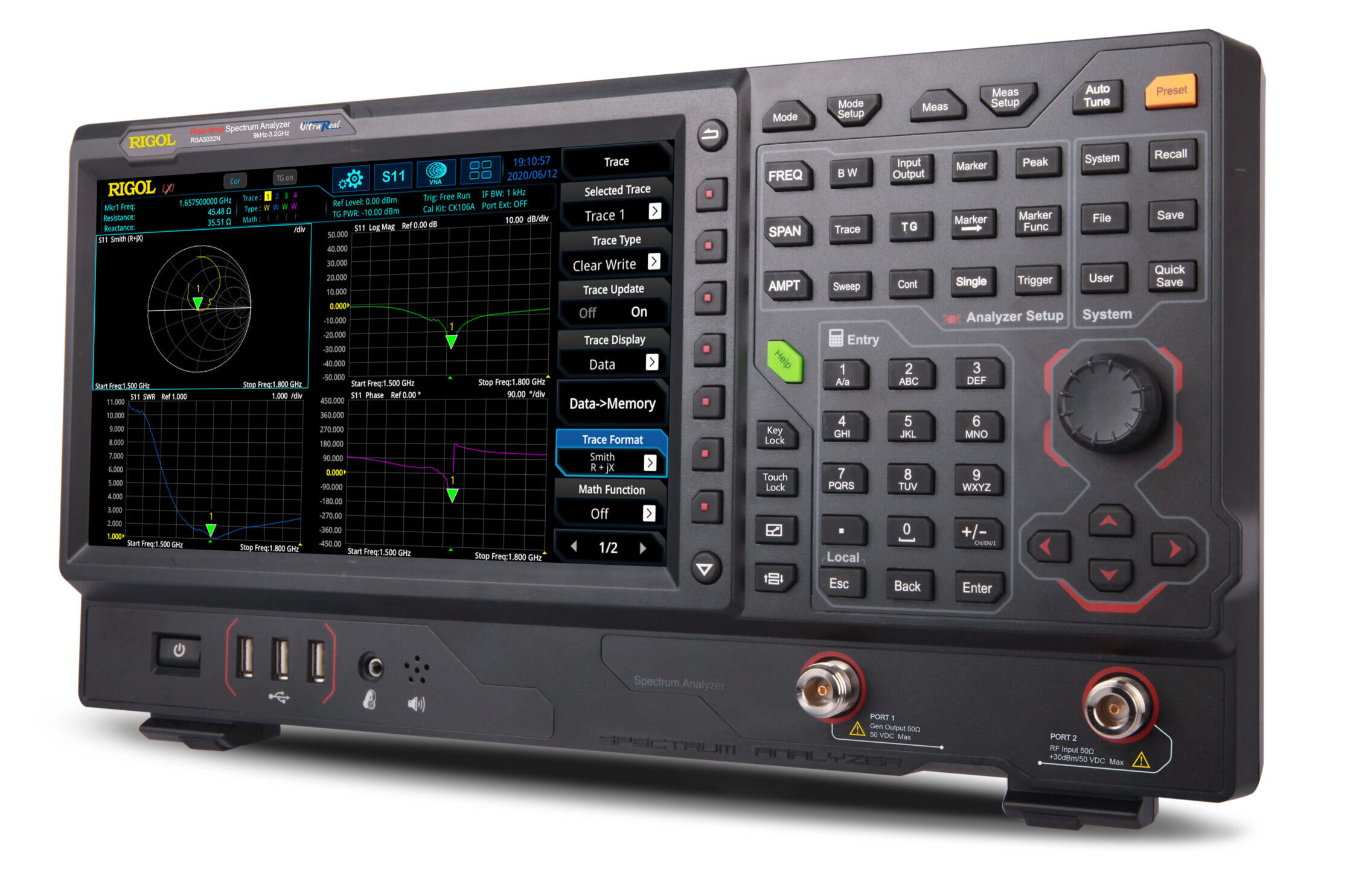
Rigol RSA3000N/5000N Real Time Spectrum Analyzers include a built-in tracking generator to offer real-time spectrum analysis and vector network analysis up to 6.5GHz with S11 and S21 reflection and transmission analysis. 

Saelig Company, Inc. has announced that the Rigol RSA3000 and RSA5000 Real Time Spectrum Analyzer series now includes five “N” versions which offer vector network analysis up to 6.5GHz.  Built on Rigol’s Ultra Real platform, these VNAs offer S11 and S21 reflection and transmission analysis.  They feature multi-touch user control via a 10.1” LCD touchscreen. Front panel buttons, keyboard, and mouse input are also available for a straightforward user interface. They run on a Linux operating system to provide a reliable and stable interface, with remote communication access also available.

Customers needing to characterize active or passive components, identify signal path errors, or tune antennas will benefit from this VNA solution, which enables complex measurements including distance to fault and S parameters.  S11, or forward reflection co-efficient, allows engineers to quickly visualize and measure a component’s response on a Smith chart and polar plane while measuring the component’s magnitude and SWR. This is important when characterizing the performance of passive components such as attenuators, splitters, and filters.  S21, or forward transmission coefficient, allows engineers to quickly visualize how amplifiers, filters and cabling components affect impedance or phase as a function of frequency. View phase or group delay as a function of frequency or magnitude to quickly determine and confirm critical specifications. Distance to fault measurements allow engineers to easily debug connectivity issues that cannot be seen from visual inspection. The spectrum analyzer uses signal reflections to calculate the distance to a fault anomaly.  It is useful for debugging communications system and completing cable test as well as for optimizing performance and throughput of a network. The Vector Network Analysis mode complements the other analysis capabilities of Rigol’s Ultra Real spectrum analyzers, including the advanced measurements in Smith mode, real time visualization, EMI pre-compliance analysis, and vector signal analysis tests. An optional Preamp adds 20dB gain to input signals.

The analyzer series measurement possibilities include EMI, RTSA, VSA, and VNA modes in addition to the traditional GPSA mode. Engineers may find it convenient to address multiple RF test challenges with just one instrument, effectively reducing their time and costs and greatly improving their working efficiency.   Advanced Measurement mode provides settings required for transmitter testing such as multichannel power, ACP, and occupied bandwidth.  Quickly recall the limit line compliance with the CISPR standard (e.g. EN55011, EN55012, etc.) to carry out pre-test and monitor the target point with three different detectors.

Made by Rigol Technologies Inc., a leading manufacturer of precision electronic instrumentation for test and measurement, the RSA32000N/5000N series of VNAs are available now from Saelig Company, Inc., their USA technical distributor.

Meet the New Affordable Multi-Color E-Paper Display from Waveshare

E-paper displays need no introductions. They are E-paper displays are fantastic displays, especially for low power applications. However, one shortcoming these displays have is their monochrome black and white nature which literally takes the color out of the things displayed. Some new displays have been able to add one more color but none has been able to give users the kind of color dexterity that is available with other displays like the TFT LCD. All of this is, however,  set to change, as the display manufacturing giant, Waveshare, recently announced the launch of a new 5.65″ 7-color ACeP e-Paper display.

While the display is based on the traditional microcapsule electrophoretic technology used in all e-paper displays, unlike the regular monochrome e-paper displays which represent a pixel data on the display with one bit (0 and 1, black and white), colored e-paper displays represent each pixel with more than one bit, with up to 4bits used in representing every pixel in the ACeP 7-color display, making it easy for developers to represent the colors during firmware development.

Some highlight features of the display include:

  • Advanced Color ePaper (ACeP) technology, supports 7-Color display
  • No backlight and displays last content for a long time even when power is disconnected.
  • Ultra-low power consumption, basically power is only required for refreshing
  • SPI interface, for connecting with controller boards like Raspberry Pi/Jetson Nano/Arduino/STM32, etc.
  • Onboard voltage translator, compatible with 3.3V / 5V MCUs
  • Comes with development resources and manual (examples for Raspberry Pi/Jetson Nano/Arduino/STM32)

The technical specifications of the display are equally impressive with a 120s refresh rate and a wide 170 degrees viewing angle. More technical specifications of the display are provided in the table below:

OPERATING VOLTAGE 3.3V/5V DISPLAY COLOR ACeP 7-Color
INTERFACE 3-wire SPI, 4-wire SPI GREY SCALE 2
OUTLINE DIMENSIONS 138.5 × 100.5mm FULL REFRESH TIME 15s
DISPLAY SIZE 114.9 × 85.8mm REFRESH POWER 50mW (typ.)
DOT PITCH 0.1915 × 0.1915mm STANDBY CURRENT <0.01uA (almost none)
RESOLUTION 600 × 448 pixels VIEWING ANGLE >170°

Waveshare has been one of the frontline developers of e-paper displays and has launched quite a number of innovative displays like the NFC Powered 7.5″ e-Paper among others, but with the 7-Color ACeP Display, they are redefining the e-paper game, inputting an element that will definitely take the bar on the type of things that can be done with e-paper displays a little bit higher.

The 5.65″ ACeP display is currently available for sale on Waveshare’s store for $74.99, which is arguably a fair price for the quality, size, and features embedded in the display.

More information on the display, its features, and applications/use with different development boards can be found on its wiki page on Waveshare’s website.

13 Amazing Gerber Viewer Software for Windows

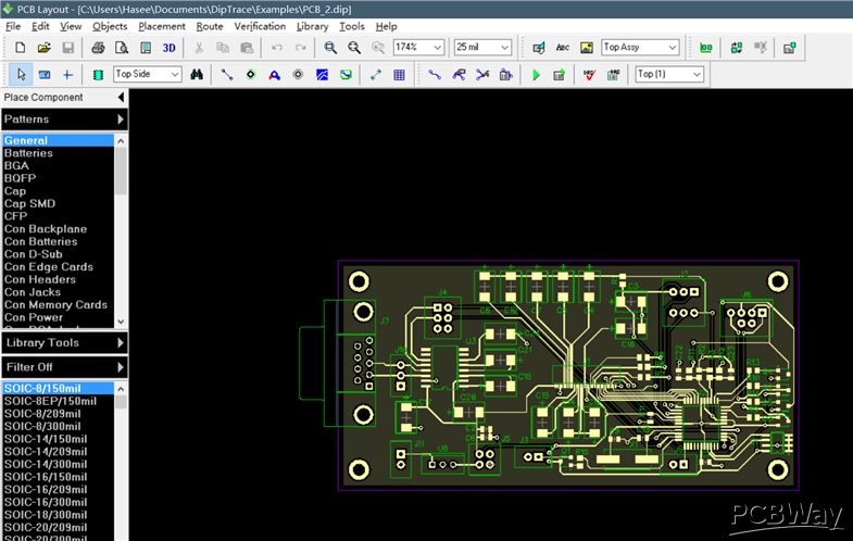
Gerber Viewer Software for Windows is a software that enables you to open and view Gerber files (GRB files) through the help of their extensive toolset. Some of this software are Gerber editor software also and allows you to view and make changes to Gerber PCB designs. The Gerber file viewer software can export the design in various formats, like SGV, PDF, PNG, PDF, JPEG, etc. You can also take a print out of the design if you want. We have various Geber Viewer software, but I’ll be discussing 12 popular ones.
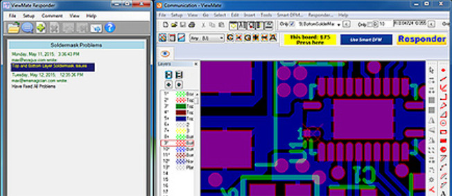
ViewMate

ViewMate from Pentalogix features a broad set of tools available for enhanced viewing functions. Its large array of selection tools enables you to select components, layer options to hide/delete/add layers, visibility toolbar to change layer/component visibility and do much more. It also enables you to select a distance unit from inch, mm, mil, and cm to measure the distance between components. Another function it has is allowing you to add traces/paths to a diagram as orthogonal trace, 90 degrees trace, elbow, circle, add text, etc., but you cannot save the drawing. The drawing with new additions can also be printed. It offers you the ability to experiment with the layers of a Gerber file. You can choose to change the visibility, change the color, and stretch the layers.
GerbMagic

GerbMagic is a free viewer for Gerber RS-274x and Protel ASCII PCB (Protel v2.5 to v2.8 formats). It can also convert Gerber RS-274x and Protel ASCII PCB to PostScript, PDF, TIFF, BMP and RID formats. It is free, simple to use, and feature-rich Gerber Viewer software. It features all the basic tools needed to view Gerber files, such as Layered view, zoom, move, align, and Measure tool as well. You can also save a Gerber file as raster or vector image formats, like: bmp, eps, pdf, tiff, etc.
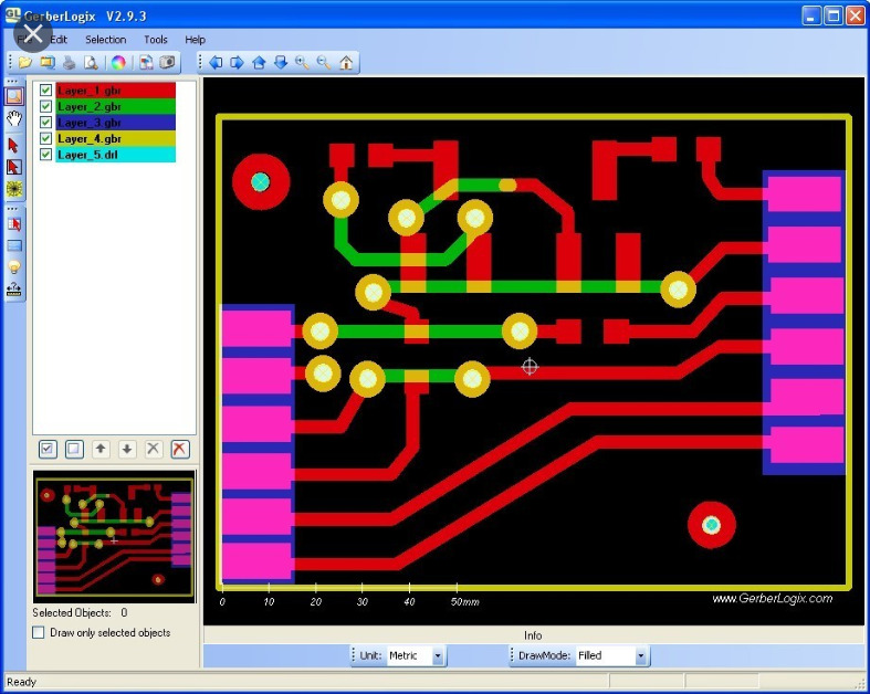
 

GerberLogix

GerberLogix is another simple to use GRB file viewer for Windows. It enables the user to easily manage and view various layers of a Gerber file. You can move the layers up or down manually. It is equipped with all the tools to view all layers, zoom objects, select objects, move objects, etc. Another feature of it is measuring distance between point to point, object to object, and center to center. You can also change the color of layers and objects for enhanced view, and preview a drawing before you print it. Finally you can export Gerber as tiff, jpg, png, and bmp, offering the option of either exporting visible area, or complete area. The Freeware license is only valid for uncommercial usage. A license for commercial usage is available for 109 Euro (plus VAT) per workplace.
 

GerberGrab

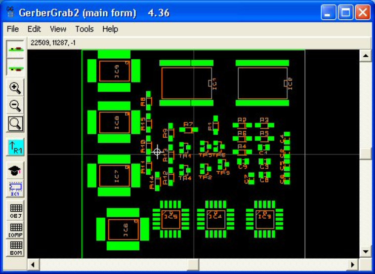
GerberGrab enables basic GRB viewer tools to view Gerber files. You can view the top and bottom sides of PCB layers. Like others, you can view layers separately by selecting or deselecting. You can also search shapes in Gerber files, carry out component scaling and rotation, and generate a component list in CSV. These features are highly valuable for anyone in the PCB manufacturing industry, particularly for contract manufacturers, who may need to check or create bills of material, build documentation, or placement lists, rapidly, off-line and with a high degree of automation.
 

ZofzPCB

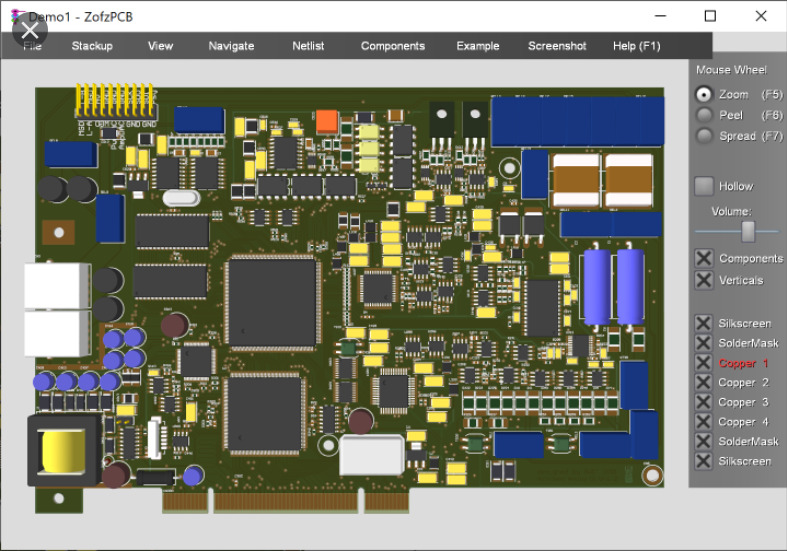
For advanced GRB software, ZofzPCB can do the trick. It is an advanced software to view GRB files. It enables you peel each layer of PCB design separately, allowing you to have a detailed look at the components. This allows you have a separate view of components, silverscreen, solderMask, copper, etc. The software allows you to perform several actions with mouse scroll actions after pressing respective buttons for them, such as: Zoom (F5), Peel (F6), and Spread (F7). ZofzPCB allows you to selectively view/hide components, silkscreen, soldermask, and copper.

Another option lets you view free/blank space on the design board. Another thing you can do with the ZofzPCB is to view the design as wireframe, edit object colors, view as X-ray, or as typical CAD drawing. You can also generate a report with details of components, pins, nets, PCB nodes, IPC nodes, and errors. The ZofzPCB enables you to get realistic 3D rendering from your Gerber files that shows you just how your finished board will look and unveils errors that are difficult to detect in a 2D view. You can also cross-check – synchronized schematic and PCB browsing.
 

Gerber Viewer

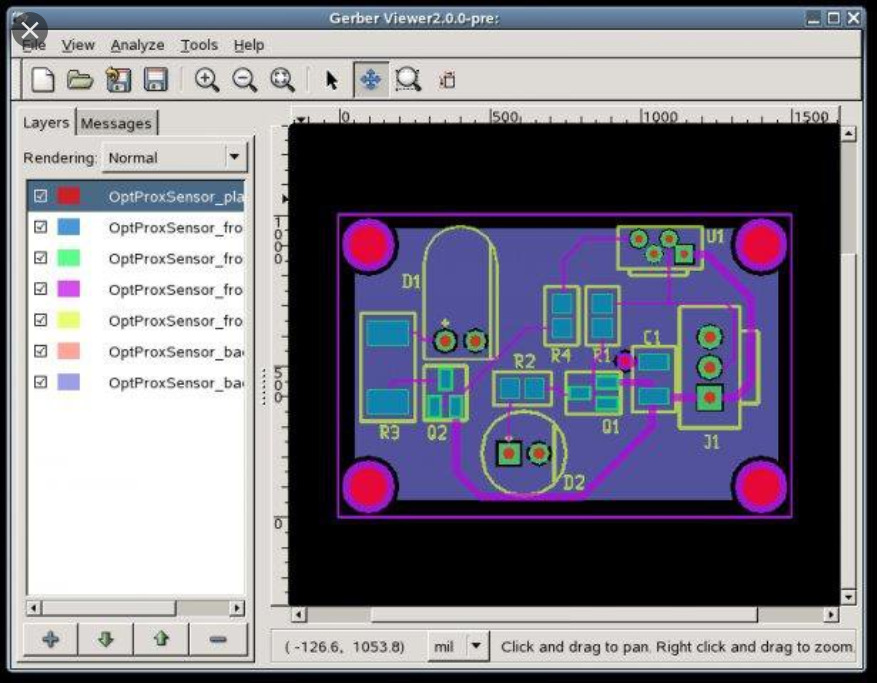
Gerber Viewer features a simple tool with simple viewing options. It enables you to import files to view them, and the tools allows you have a view of the top and bottom view of designs. If you want to view and hide layers, you just have to select and deselect them. You can import Gerber 724-X and IPC2581 files also. The software is an open-source Gerber viewer for Windows.
 

Viewplot

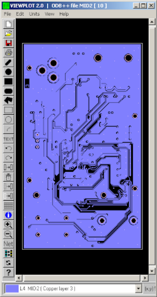
Another GRB editor is Viewplot, which is a paid GRB editor, that allows you view Gerber files for free. It enables you have a good layer-wise view of Gerber files. Every layer has a different color, and by selecting a layer, you can see a highlighted view of it. It enables you to add text, circle, arc, rectangle and other shapes. However, you can not save the file. You have the ability to turn on/off the grid view, and diagram dpi can be changed to 300, 360, 600, 720, 1000, 1200, 1440, 2000, or 2400. You can translate your CAD data in seconds, as a standalone tool or integrated within existing CAD processes. Viewplot also enables you to inspect various CAD formats, take measurements, and manipulate data. You can create high-resolution PDF documentation within the graphical user interface or in batch mode.
 

GerbEx

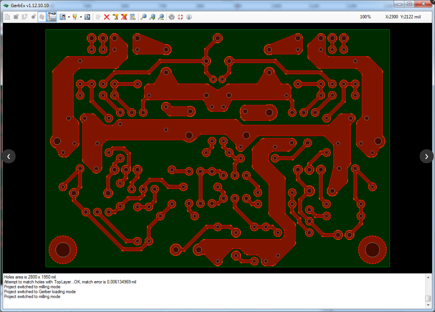
The open-source GerbEx has simple viewing options. The software enables you generate G-code for PCB milling and/or drilling from Gerber and Excellon files. You can zoom and move the drawing around to view GRB files. Also, the software enables you to manipulate layers of the loaded design, with each layer being represented in a different color. Additionally, you can hide or unhide layers and duplicate layers.
 

FlatCam

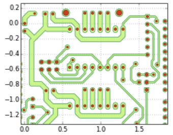
FlatCam Gerber viewer software enables you to edit PCB board or create one. You also have the feature of viewing design layers. Another feature of the software is the option of selecting a component to view its property, and you can also measure distance between two components in mm or inch. You can also isolate routing, board cutout, and non-copper region for a detailed view. You can add shapes like arc, circle, rectangle, etc. You can make double-sided PCBs quickly with a specialized built-in tool that allows you to invert your layers and create alignment guides. One key  feature of the software is the TCL console, which enables the ultimate flexibility for users to automate and implement their own features. Finally, you can view GRB and G-code files, and also export designs as SGV files.
DFM Now

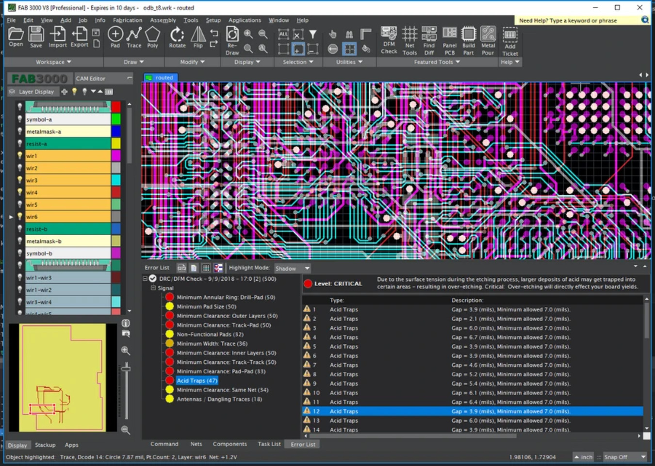
Another GRB editor we will talk about is the DFM Now. The software enables you have a detailed look on Gerber files, like having a top/bottom view of drawings, viewing all layers of files easily, and separately choosing each layer to show/hide. The software also offers a slider zoom, which makes viewing Gerber file very easy. Another feature I like, is the ability to make the board translucent, and view component info when clicked. The software makes it easy to move, delete, rotate, mirror, and flip components. Also, you can add traces, circles, text, etc to the drawing. You cannot save the file, but you can make a printout of the file.
 

LayoutEditor

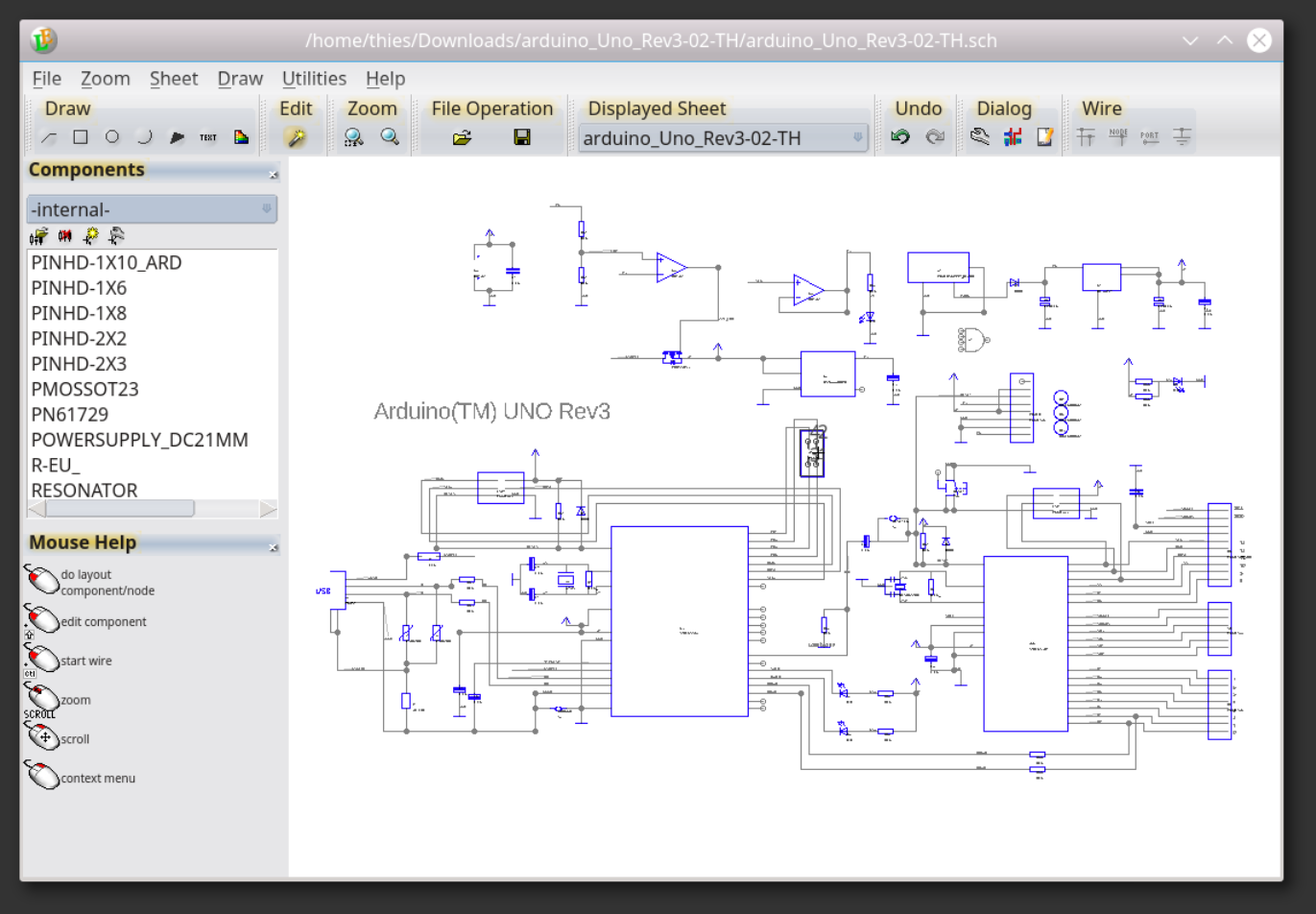
LayoutEditor is one of the popular software to edit designs for MEMS and IC fabrication. It is also often be used for Multi-Chip-Modules (MCM), Chip-on-Board (COB), Low temperature co-fired ceramics (LTCC), Monolithic Microwave Integrated Circuits (MMIC), printed circuit boards (PCB), thick film technology, thin-film technology or any other technology using photomasks. It is a free Gerber editor that enables you view and select layers of PCB design, and you can make use of the zoom feature to enhance your view. You can also move and rotate objects, and measure the distance between two objects. You can edit Layers with the software, and add components.
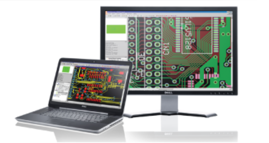
 

GC-Prevue

With GC-Prevue,  you can view and print Gerber files for 65 USD per year, with support for CAD generated drawings. You can also manipulate layers. The software enables you to set the unit for measuring the distance between parts. You can edit layers by setting layer visibility, deleting layers, and importing layers. You can use the software for verification of design data and quoting.
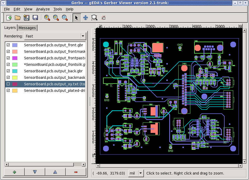
gerbv

Gerbv is a free viewer for Gerber RS-274X files, Excellon drill files, and CSV pick-and-place files. Gerbv is a native Linux application, and it runs on many common UNIX platforms. A Windows version is also available. If you’re looking for a free tool with which you’ll be able to analyze and validate Gerber (RS-274X) files, try downloading Gerbv. Gerbv is a feature-rich software utility that you can use to view Gerber files, namely those with the RS-274X format. It features several handy tools which should meet the requirements of users’ preferences.

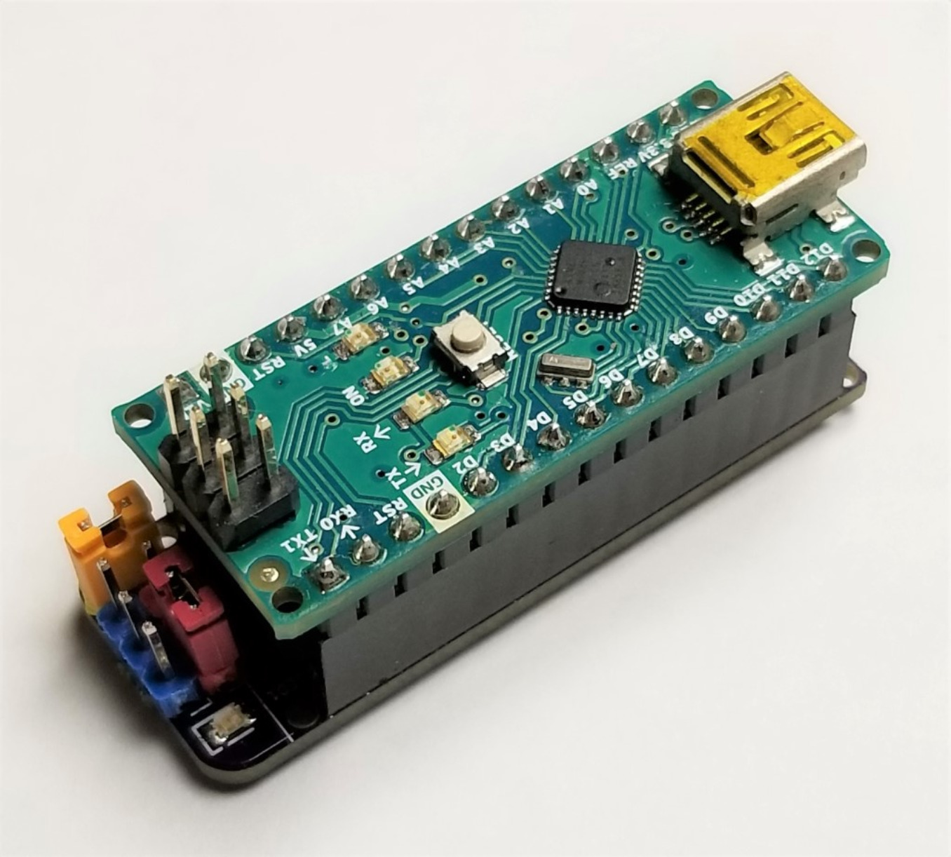
DIY Arduino Nano HV UPDI Programmer

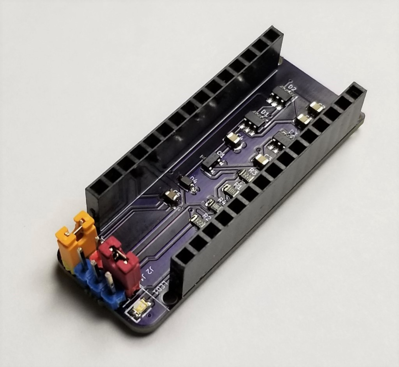
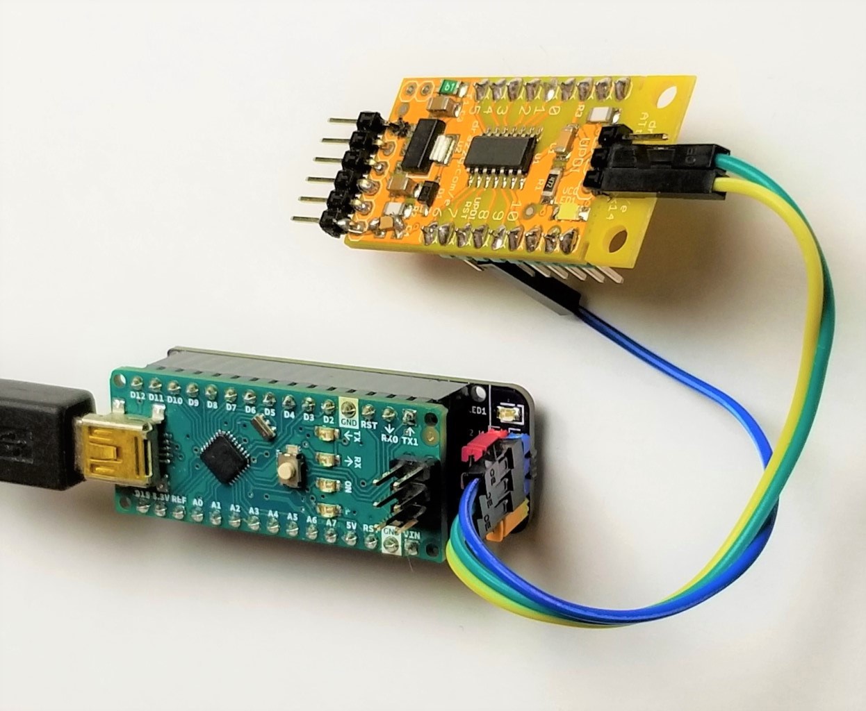
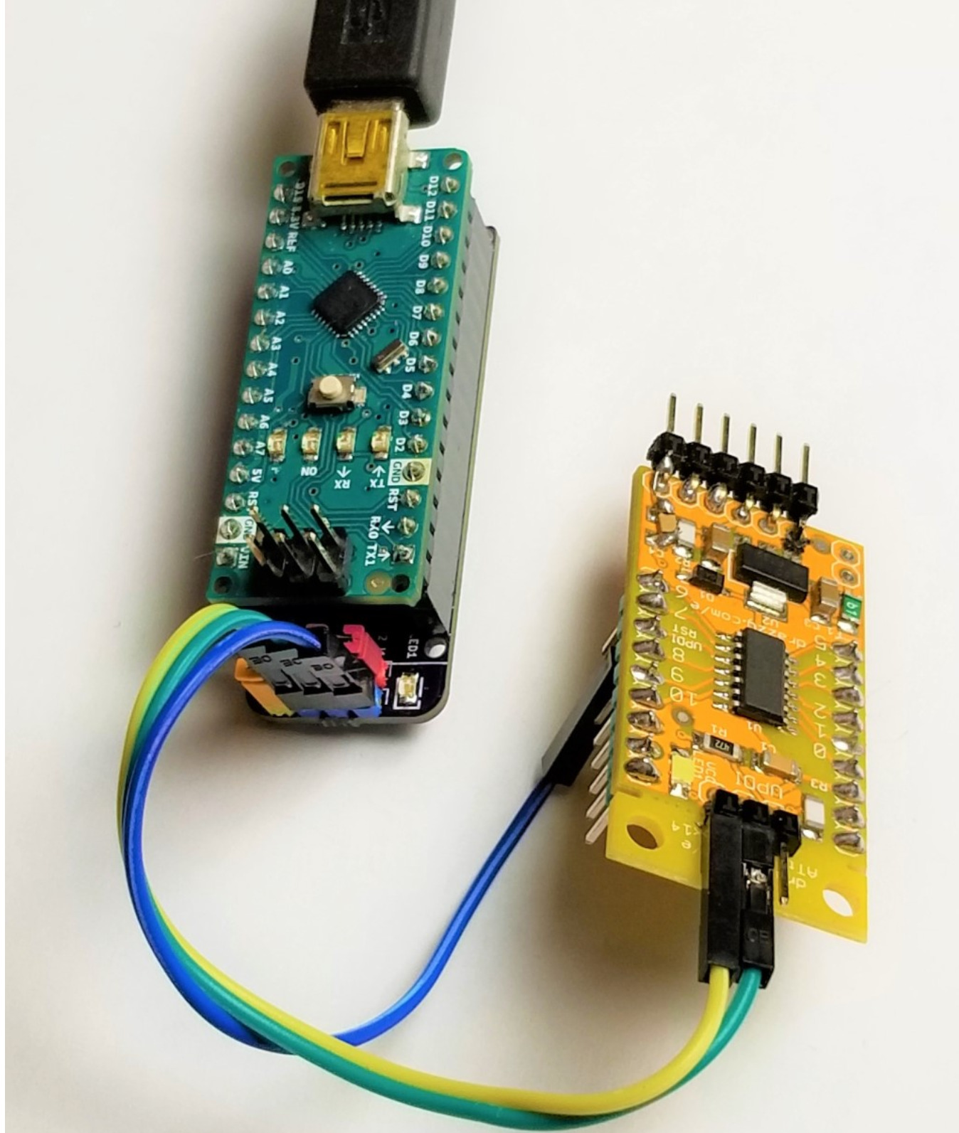
In May, Arduino released a guide on how you can create a UPDI programmer for under $10. Now Dlloydev has posted a guide on Github how to make an Arduino Nano HV UPDI programmer. The Nano HV UPDI programmer will enable you to use the additional configuration settings for the UPDI pin without the fear of getting locked out from the MCU. The Nano HV features 3 programming modes: UPDI, HV or PCHV, with the target voltage at 5V.

To get started, you have to install megaTinyCore, then Install the HV Programmer Firmware. After installation, you click on the green “Clone or download” button, then select “Download ZIP“. When you are through with the download, you unzip the file in a folder on your PC, then load the sketch “jtag2.updi.ino” into the Arduino IDE. Note that you have to uninstall the Write Protect jumper from the programmer for you to carry on with the project, the reason for this is that with a jumper installed, the auto-reset circuit of the programmer is disabled. This protects against accidental overwriting of the firmware and also ensures quick programming sessions by eliminating extra bootloader delays that would be caused by triggering the reset. Moving forward, from the IDE, you select Tools > Board > “Arduino Nano”. Then you select Tools > Port > (serial port used by the Nano). After that, you select Sketch > Upload.

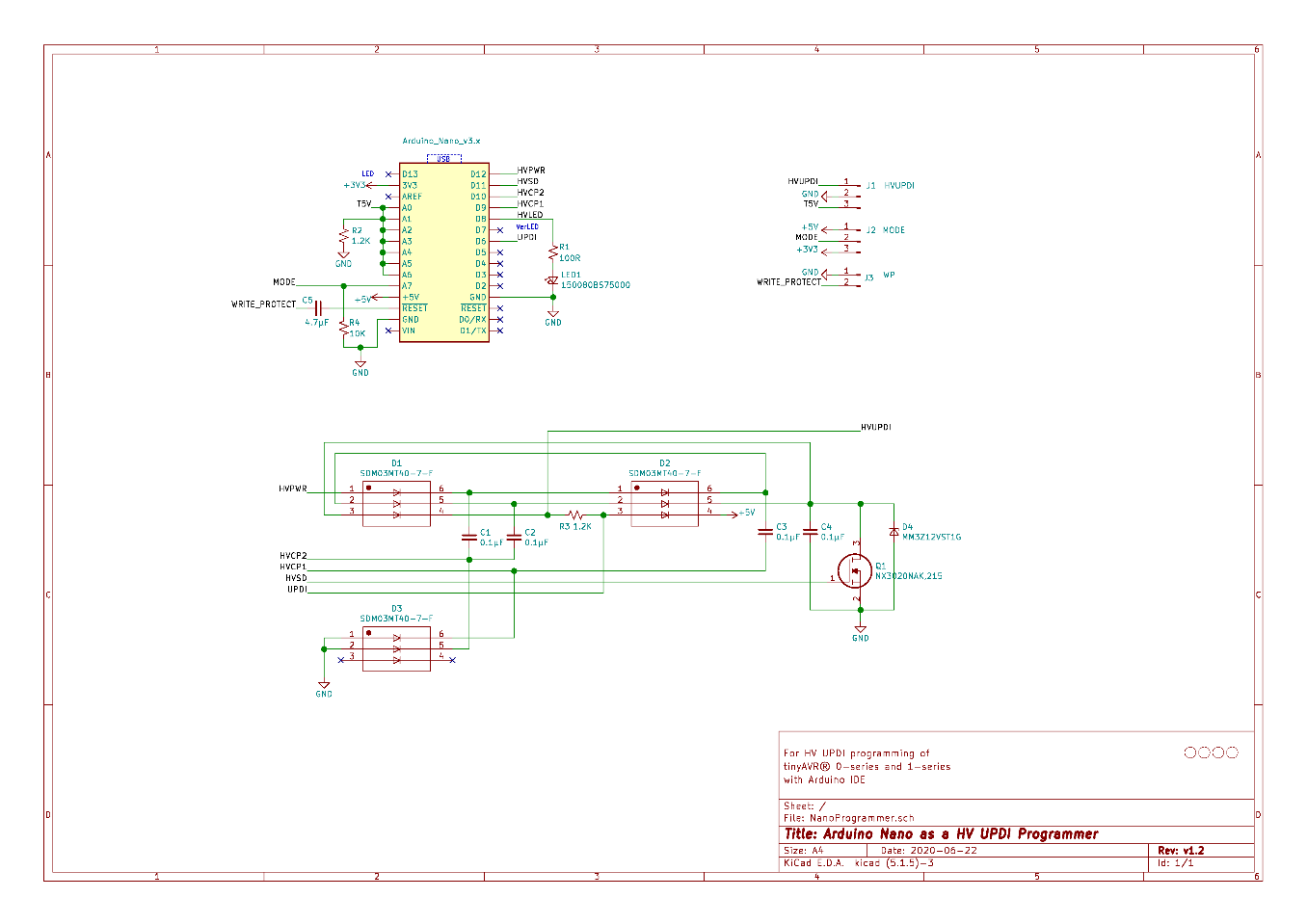
   Schematic

When you are through with the upload, You have to install the Write Protect jumper. Finally, from the IDE, select Tools > Programmer > “jtag2updi (megaTinyCore)”. After going through all these processes, you can now use the Nano HV programmer to “Burn Bootloader” or to “Upload Using Programmer” from the Arduino IDE. However, you have to make sure to choose the appropriate board, chip, and port setting target. Then you can choose Programmer Mode Selection you want. To know if it is programming mode, the red and yellow LEDs will be ON. On startup, the yellow LED will indicate overload status. When the programming mode is set to HV or PCHV, bright blue LED flashes to indicate the HV pulse during programming of the target. On startup, the OVL sense analog input (A6) will be checked. If the voltage on A0-A5 (target power) has dipped below 90% (4.5V), then the yellow LED will indicate overload status by blinking at 4Hz. The user will then need to correct the problem and press reset to clear.

The programmer has three modes you can choose. They include:

  • UPDI Mode: This mode would be used when the UPDI pin is configured as UPDI or for any target device that isn’t HV tolerant.
  • HV Mode: This mode applies the 12V UPDI enable sequence (HV pulse) at the start of the programming sequence. This temporarily reconfigures the UPDI/Reset pin to UPDI mode which will remain in this state until the next POR. This allows programming to occur when the pin is configured as Reset. A power-on reset (POR) needs to occur for any fuse setting changes to take effect.
  • PCHV Mode: Power Cycle High Voltage mode (PCHV) will initiate a power cycle and HV pulse at the start of the programming sequence. At the end of the sequence, a second power cycle will occur which causes any new fuse setting to take effect. The power cycle OFF duration has been set to 10ms. This mode would be used when the UPDI/Reset pin is configured as Reset or as GPIO.

In conclusion, this build enables you to create an Arduino Nano HV UPDI programmer with little resources, rather than having to spend many hundreds of dollars for a commercial one. You can get more information in the guide on Github.

Hardkernel’s Powerful Odroid-N2 Single Board Computer Gets an Upgrade – Odroid N2 Plus

With Amlogic S922X Rev. C Processor Clocked at up to 2.4 GHz, Odroid-N2 Plus is possibly the fastest open-spec single board computer the world has ever seen.

The rising technological advancements in IoT plus the increase in demand for smart connected devices have resulted in more significant growth of the single board computer market over the past few years.

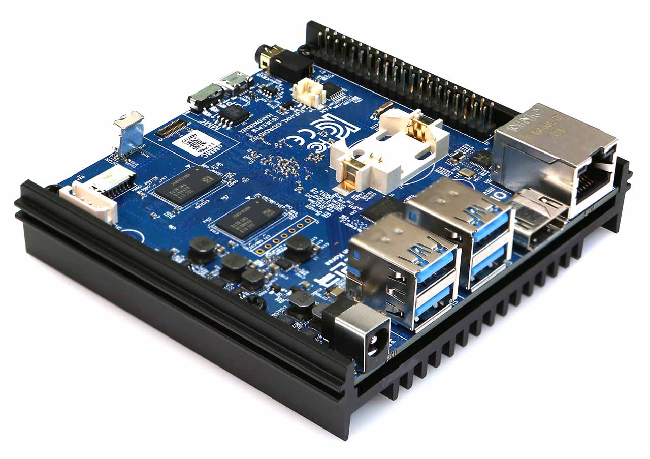
Barely 15 months after Hardkernel released ODROID-N2, one of the fastest ARM single board computer with hexa-core Cortex A7/A53 processor and 2GB/4GB RAM, the company has come back to announce an upgrade of the high-end SBC with what is likely to be the fastest open-spec ARM board around, the Odroid-N2-Plus or simply N2+.

The Linux-driven Odroid-N2 Plus takes advantage of a newly revised version of Amlogic’s S922X with advanced CPU core power rail and higher clock frequencies. The new Rev-C in the N2+ offers a 400 MHz clock speed boost over the Rev-A in Odroid-N2, bringing the 4x Cortex-A73 cores to 2.2 GHz from 1.8 GHz and the 2x Cortex-A53 upwards to 2.0 GHz from 1.9 GHz. With this speed, the N2+ board will probably match the more expensive SBCs on all sides.

Some highlight features and specification of the board include:

  • On-board Arm Mali-G52 GPU
  • 2GB or 4GB DDR4 RAM at 1320 MHz
  • 8 MB SPI flash and eMMC flash module
  • MicroSD card slot
  • 40- pin GPIO header with 2x I2C, UART, 2x ADC, 6x PWM, SPI
  • 1x micro USB 2.0 OTG port and 4x USB 3.0 ports
  • HDMI 2.0 up to 4K @ 75 Hz and composite video + stereo audio
  • 2x LEDs, IR receiver and 2-pin header each for RTC battery and fan
  • Standard CR2032 coin cell battery holder for the RTC, and
  • 7.5 – 20V DC input.
  • Operating Systems: Android 9 Pie, Ubuntu 18.04/20.04 and Linux 4.9.162 LTS
  • Weight: 200g
  • Dimensions: 90 x 90 mm (with heatsink) or 100 x 91 x 18.75 mm (without heatsink)

Hardkernel claims that the N2+ is capable of offering twice the performance of a Raspberry Pi after testing over 300 samples of the N2+ board to discover that 4x Arm Cortex A73 cores can also be overclocked to 2.4 GHz, about 33% performance increase over the original Odroid-N2 board and roughly twice the speed of a Raspberry Pi 4.

The 2GB version of the N2+ board is available for preorder on Hardkernel’s store for $63 while the 4GB version goes for USD $79, with shipping scheduled for July 20 and 24 respectively for both options. In addition to the mainboard, an optional $4 cooling fan is also available for users who may be running the board in an overclocked state or at high temperatures.

More details on the Odroid-N2 Plus may be found on the product’s announcemet.

xMEMS Launches Montara, World’s First Monolithic True MEMS Speaker

Today xMEMS Labs emerged from stealth mode to reinvent sound with the introduction of Montara, the world’s first monolithic true MEMS speaker, delivering high fidelity, full-bandwidth sound and low total harmonic distortion (THD) for sealed in-ear personal audio devices, including true wireless stereo (TWS) earbuds. Montara is also the world’s first IP-57 rated microspeaker, enabling water and dust-resistant earbuds. Consumers will benefit from enhanced audio fidelity with raised levels of clarity and detail for instruments and vocals, extremely low latency, waterproof earbuds, and longer listening times.

“With on-the-go media consumption on the rise such as subscription music, podcasts, video, audiobooks and mobile gaming, consumers are increasingly demanding enhanced audio quality and extended listen times between charges,” said Joseph Jiang co-founder and CEO. “Until now, the industry has relied on antiquated, centuries-old multi-component voice coil speakers requiring labor-intensive, high variability factory assembly lines. Our revolutionary Montara product is a game changer for delivering a new combination of audio fidelity, size, energy consumption and uniformity not possible with traditional voice coil approaches.”

Montara eclipses early hybrid-MEMS speakers by implementing the entire speaker (actuator and diaphragm/membrane) in silicon, reducing package height and eliminating driver matching and calibration due to inherent variability in membrane assembly. The combination of Montara’s design innovation and monolithic capacitive piezo-MEMS manufacturing material results in precise actuation, quality sound, speaker-to-speaker uniformity and repeatability.

“It’s exciting to see the first monolithically integrated MEMS (transducer and membrane), full-bandwidth microspeaker for the rapidly growing hearables market,” said Dimitrios Damianos, Technology & Market Analyst at Yole Développement (Yole). “The replacement of traditional voice coil speakers and balanced armatures with a complete semiconductor component provides a scalable design that claims significantly lower power and latency, while xMEMS’ fabless model ensures high volume repeatability. Technology advancements like these could improve the quality and adoption of in-ear personal audio devices.”

“I have reviewed the audio test data from xMEMS and from this it appears to be a viable product, maybe even a game changer for TWS and IEM earphones. One small step for audio, one giant step for MEMs speakers,” said Michael Klasco, president of Menlo Scientific.

Montara Features:

  • Sound Quality
    • Full bandwidth (20Hz-20kHz) with flat frequency response at >110dB SPL
    • Ability to replace multiple balance armature drivers with a single chip
    • Better SPL/mm3
  • Consistency
    • Highly uniform and reliable semiconductor process
    • Eliminates driver matching and calibration
    • Consistent silicon membrane movement enables active compensation for low THD (< 0.5% (200Hz ~ 20KHz))
  • Low Latency
    • <0.1ms mechanical latency enables active noise cancelation (ANC) across wider frequency range
  • Robustness: monolithic piezoMEMS 10,000g mechanical shock resistance
  • Longer listen times
    • Montara’s capacitive vs. current-driven architecture reduces driver power consumption
  • Water-proof: IP57 water immersion and dust resistance without special membrane
  • Small size with very low profile at 1mm thickness

Availability

Montara samples and evaluation kits are available in July to select customers, with mass production orders expected in the first quarter of 2021. Montara will offer two LGA package options: Standard (6.05 x 8.4 x 0.985mm) and Side-Firing (Phi 6.1mm; 6.05 x 1.0 x 8.4mm).

uEye LE AF camera models from IDS feature a practical autofocus function

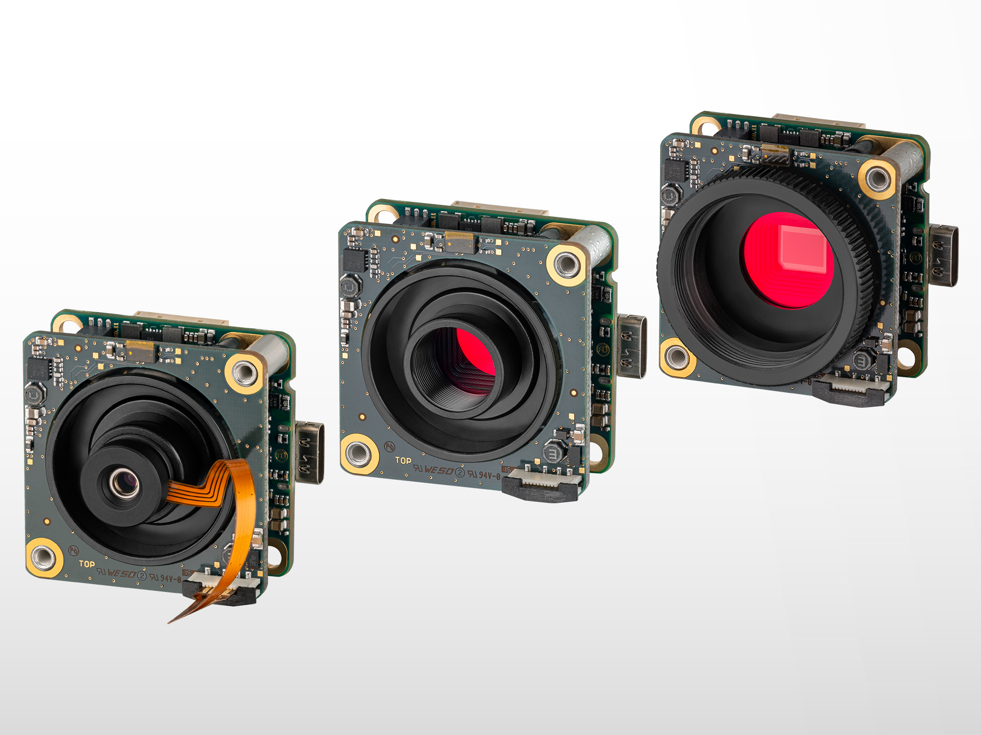
IDS extends selection of automatically focusable board-level cameras. Thanks to their practical autofocus function, uEye LE AF industrial cameras deliver perfectly focused images even with frequently changing object distances.

IDS Imaging Development Systems GmbH now offers additional camera variants with 2.1 and 3.1 MP Sony sensors which provide more flexibility in terms of application design and camera integration. For the first time, the company also offers models with upright USB Type-C alignment in this product family.

In addition to the previously available uEye LE AF cameras with 6.4 MP (IMX178, 58 fps) and 18.1 MP (AR1820HS, 20 fps) sensors, customers can now also purchase models with 2.1 (IMX290, 120 fps) or 3.1 MP (IMX265, 80 fps). All cameras feature a USB 3.1 Gen 1 interface, USB Power Delivery – which can be used, for example, to power an LED light source or a photoelectric sensor – and allow the use and control of liquid lenses.

The autofocus function ensures sharp images in the blink of an eye, even if the lens is not physically accessible or if the distance between the lens and the object changes frequently. The board-level cameras are therefore particularly well-suited for applications in fields such as logistics (e.g. for parcel acceptance and sorting) or traffic monitoring. Due to their compact design with dimensions of only 36 x 36 x 20 mm they also prove their strengths in embedded vision systems. This means that they are also interesting for integration into small medical or industrial devices.

Further information: https://en.ids-imaging.com/store/products/cameras/ids-interface/usb-3.1-gen.-1/ids-family/le/ids-camoptions/autofocus.html

Graphcore launches 7nm AI processor

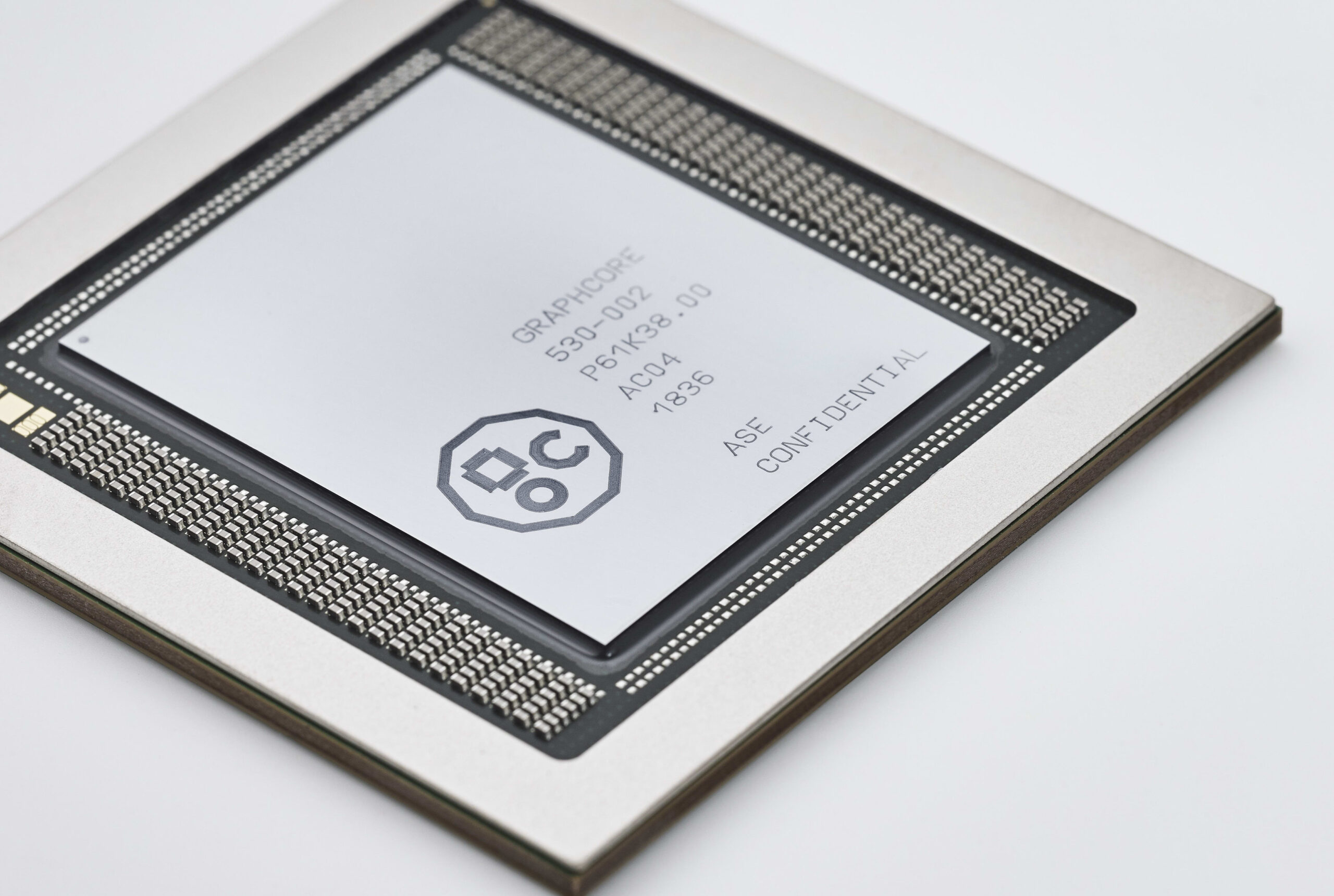
AI processor company Graphcore Ltd. (Bristol, England) has announced its second-generation ‘Colossus’ intelligent processor unit (IPU), the GC200, claiming the 7nm chip is the world’s most sophisticated microprocessor. By Peter Clarke @ eenewseurope.com

The company has also introduced a 1U board containing four GC200 processors that it calls the IPU-Machine or M2000.

The chip is manufactured by foundry TSMC in a 7nm FinFET manufacturing process allowing far greater integration than was possible with Graphcore’s first IPU, which was implemented in TSMC’s 16nm FinFET process.

Graphcore CEO Nigel Toon described the GC200 as “the world’s most advanced processor” in a Youtube video stating it contains 59.4 billion transistors, 1,472 independent processor cores able to support 8,832 computing threads in parallel. The chip has also tripled the amount of on-chip memory able to support processors moving up to 900Mbytes.

This results in a naked maximum performance of 250 TeraFlops of AI compute at FP16.16 and FP16.SR (stochastic rounding). The GC200 supports much more FP32 compute than any other processor, the company has claimed.

As with the first IPU the GC200 was designed to use Graphcore’s Poplar software development and management environment. However, the company has also introduced changes in data storage to increase off-chip memory bandwidth to 180Tbytes per second and in inter-IPU communications fabric, Toon said.

The net result is an 8x improvement in benchmarked performance compared to the first IPU. The company claims that systems based around its M2000 racks will be 16 times higher performance than similar ones based on 7nm GPUs from Nvidia.

The IPU-M2000 delivers 1PetaFlop of AI compute and up to 450Gbytes of memory. The newly developed IPU-Fabric enables the building of IPU pods for data centres connecting up to 64,000 IPUs. The M2000 is priced at $32,450.

Related links and article: www.graphcore.ai

TOP PCB Companies