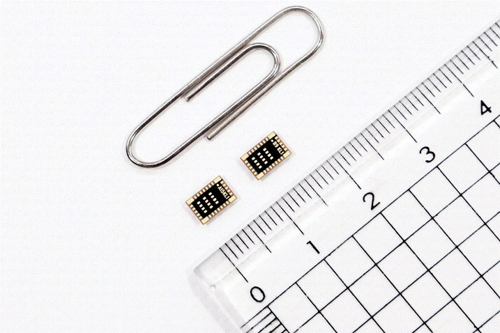
An LG Innotek official is showing a “Bluetooth low energy module for IoT.” Using this module, IoT manufacturers can freely design products in various shapes and size, and its outstanding com-munication performance enables smooth data transmission even with multiple obstacles. (PRNewsfoto/LG Innotek)
LG Innotek announced that it has developed the world’s smallest Bluetooth module. With this development, LG Innotek is gearing up to advance further into the communication module market for Internet of Things (IoT).
LG Innotek’s “Bluetooth low energy (BLE) module for IoT” is a key component that enables data communications for IoT devices such as glucose measuring patches, smart lighting, outlets, switches, wireless earphones, and hearing aids. Thanks to its low power consumption feature, the module is mainly used for IoT devices that require limited power supply, such as small wearable devices.
By linking various IoT devices to the smartphone, users can conveniently track blood glucose levels, remotely control lighting, outlets, switches, and operate wireless earphones or hearing aids at a short distance.
Notably, the IoT products featuring LG Innotek’s BLE module are small and slim but boast of excellent communication performance. With differentiated radio frequency (RF) signal design and antenna technology, and ultra-precision circuit technology, component space is reduced while the data transmission distance is increased.
By applying LG Innotek’s BLE module, IoT device manufacturers can freely design products in various shapes and sizes. This is possible because LG Innotek minimized the module size and mounting space.
LG Innotek’s module is the smallest in the world. This module is 6mm (width) x 4mm (height), which is 75% of the previous model. With ultra-precision, high-density, and ultra-fine processing technologies, more than 20 components including ICs (communications chips), resistors, and inductors, are housed in a single grain-sized product. LG Innotek’s differentiated RF signal design technology minimized component space to eliminate signal interference.
LG Innotek’s BLE module also enables device control and real-time data inquiry even if there is an obstacle between the user’s smartphone and the IoT device. This is because the communication performance of the module is increased by 30% compared to existing products.
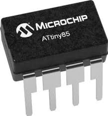
In recent tutorials, we have highlighted how useful the ATtiny series of microcontrollers are, thanks to their tiny form factor and a decent amount of processing power, which makes them good choice for projects. where keeping a small device form factor is desired. One other feature that we probably have not highlighted enough, is their low power consumption which combined with their tiny form factor, would make perfect IoT devices. The prospects of their use in low power applications like IoT becomes even more clear when you consider the little amount of power they consume in different low-power modes. The Attiny85, for instance, consumes only 2uA in sleep mode.
Being able to switch between these modes will help you build more robust solutions with longer-lasting batteries using the Attiny series of Microcontrollers. Thus, to ensure you have all you need for this, today’s tutorial will focus on how to wakeup or turnoff the ATtiny85 microcontroller to save power or for any other reason you desire.
Taking the ATtiny85 in and out of sleep modes can be done in several ways including a fully automated software process involving a triggering element like an RTC, or the use of hardware components like a switch. Adopting any of these approaches depends on the requirements for your project but for today’s tutorial we will focus on triggering the sleep mode using a switch.
The tutorial will chronicle the example built by the good folks at bitbanging which implements two kinds of behaviors:
Immediate push on/off: for this, the microcontroller will immediately go into sleep mode when the button is pressed, with all peripherals going off, and it will come back “on” when next the button is pressed
Push and Hold for on/off: This will require the button to be pressed down for a particular timeframe before sleep mode is activated/deactivated.
Ready? let’s go
Required Components
The following components are required to recreate this project;
ATtiny85
SMD to DIP Socket
Pushbutton
LED
220 ohms Resistor
battery/power supply (3.7V – 5V)
Jumper wire
Breadboard
All of these components can be purchased from your favorite online electronics component shops.
Schematics
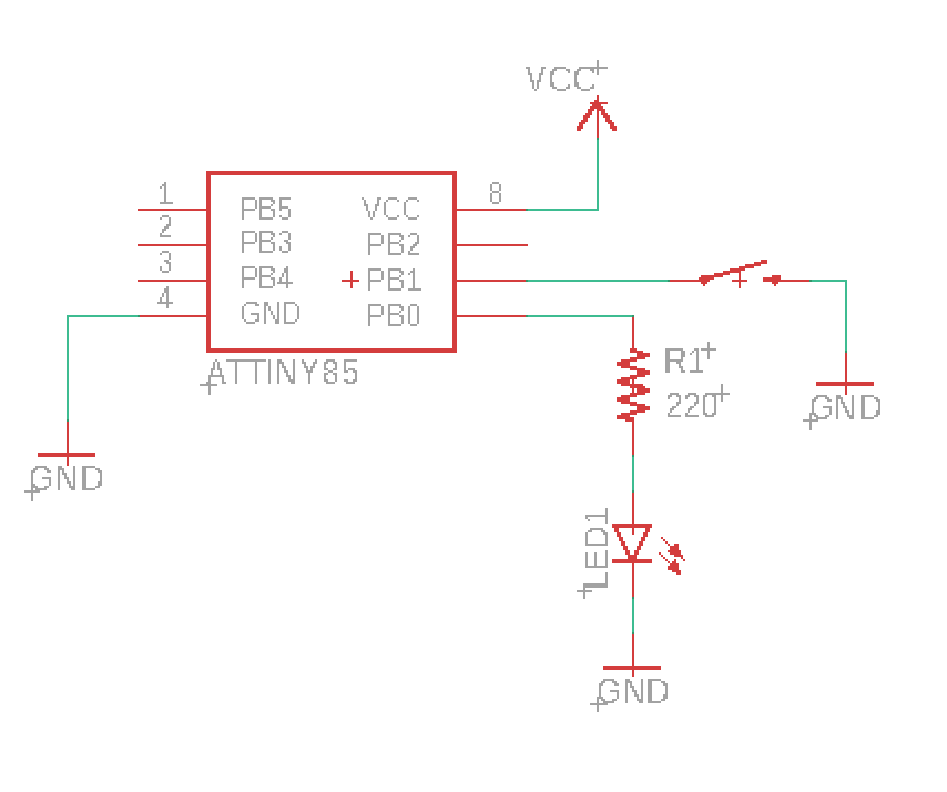
The schematics for the project is quite straight forward. Connect the components as shown in the schematics below;
Schematics Credit: BitBanging.space
The LED, which is being used to indicate the state of the ATtiny (on/off), is connected to pin PB0 of the microcontroller via a resistor (current limiting), while the pushbutton is connected to pin PB1 which is an interrupt enabled pin. You will notice the Pushbutton connection does not have a pull-up (or pull-down) resistor. We will be using the microcontroller’s internal pull-up resistor to prevent the pin from floating.
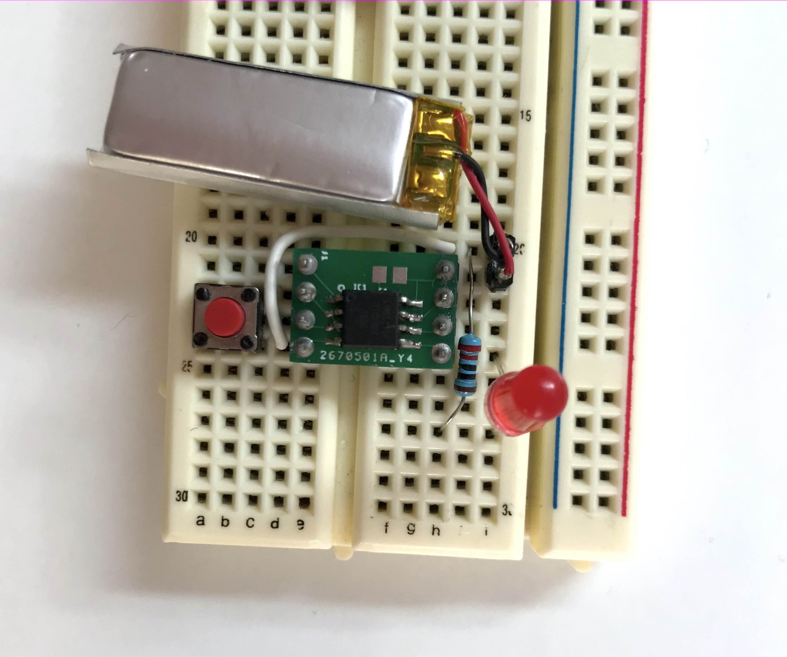
With the connections complete, your setup should look like the image below.
Credit: BitBanging.space
Go over it one more time to ensure there are no errors.
Code
While the schematic for both implementations is the same, and they both leverage interrupts, there are some differences in the code, so we will go over their codes separately. The firmware may be developed using AVR studio but if you are familiar with Arduino C, you can easily port it. We have covered several tutorials on programming ATtiny microcontrollers using the Arduino IDE.
1.Immediate Push ON / OFF
As mentioned earlier, for this implementation, we want the microcontroller to shutdown all peripherals and go to sleep when the button is pressed, and come back up the next time the button is pressed. The logic is simple; the current state of the device either on or off is stored in a variable, such that when a pin change interrupts is triggered by the push button, the device is driven from whatever state it is to the other state. So if the device was on (Running), the triggering of a pin change interrupt will take it to the off (POWER_OFF) state and vice versa.
As usual, I will do a brief run-through and explain some parts of it which I feel may be hard to follow.
We start, as usual, by including all the libraries that are required. I believe their names should easily give them away.
Next, we write the void power_off() function which dictates what happens when the microcontroller is to be switched off. The function includes commands to disable watchdog timer (WDT) and the Brown-out detector while putting the microcontroller in the PWR_DOWN sleep mode.
void power_off()
{
cli(); // Disable Interrupts before next commands
wdt_disable(); // Disable watch dog timer to save power
set_sleep_mode(SLEEP_MODE_PWR_DOWN); // Set sleep mode power down
sleep_enable();
sleep_bod_disable(); // Disable Brown out detector
sei(); // Enable interrupts
sleep_cpu();
sleep_disable();
}
Next, is the main function. The function starts with the interrupt setup, enabling the pull-up resistor on the pin and setting it as an interrupt pin. The default status of the device when powered is also set to running so that the first time the pin is pressed, it switches to the power-off mode.
int main()
{
PORTB |= (1 << BTN); // Enable PULL_UP resistor
GIMSK |= (1 << PCIE); // Enable Pin Change Interrupts
PCMSK |= (1 << BTN); // Use PCINTn as interrupt pin
sei(); // Enable interrupts
status = RUNNING; // Start ON/OFF when power is connected
DDRB |= (1 << DDB0); //Set pin 0 to output for the LE
Next, the main function listens for the interrupt trigger. If it is triggered and the state is set to running, the LED pin is turned “ON” and if it is triggered and status is set to power_off, the LED is turned off.
for (;;)
{
if (status == RUNNING)
{
/* main code here */
PORTB |= (1 << PB0); // LED Pin 0 ON
/* -------------- */
}
else
{
PORTB &= ~(1 << PB0); // LED Pin 0 OFF
power_off();
}
}
}
The last part of the code is the interrupt handling routine. The routine checks if the button has been pressed and changes the status based on the previous status.
ISR(PCINT0_vect)
{
if (BTN_STATUS) //If button is down change status
{
if (status == RUNNING)
status = POWER_OFF;
else
{
status = RUNNING;
/* initialize the device here (timers etc..)*/
}
}
}
The complete code for this implementation is provided below:
#include <avr/io.h>
#include <util/delay.h>
#include <avr/interrupt.h>
#include <avr/sleep.h>
#include <avr/wdt.h>
#define BTN 1
#define BTN_STATUS !((PINB >> BTN) & 0x01)

enum Status
{
    RUNNING,
    POWER_OFF,
};
void power_off()
{
    cli();                               // Disable Interrupts before next commands
    wdt_disable();                       // Disable watch dog timer to save power
    set_sleep_mode(SLEEP_MODE_PWR_DOWN); // Set sleep mode power down
    sleep_enable();
    sleep_bod_disable(); // Disable Brown out detector
    sei();               // Enable interrupts
    sleep_cpu();
    sleep_disable();
}
Status status; // Device status
int main()
{
    PORTB |= (1 << BTN);  // Enable PULL_UP resistor
    GIMSK |= (1 << PCIE); // Enable Pin Change Interrupts
    PCMSK |= (1 << BTN);  // Use PCINTn as interrupt pin
    sei();                // Enable interrupts

    status = RUNNING; // Start ON/OFF when power is connected

DDRB |= (1 << DDB0); //Set pin 0 to output for the LED
    for (;;)
    {
        if (status == RUNNING)
        {
            /* main code here */

            PORTB |= (1 << PB0); // LED Pin 0 ON

            /* -------------- */
        }
        else
        {
            PORTB &= ~(1 << PB0); // LED Pin 0 OFF

            power_off();
        }
    }
}
ISR(PCINT0_vect)
{
    if (BTN_STATUS) //If button is down change status
    {
        if (status == RUNNING)
            status = POWER_OFF;
        else
        {
            status = RUNNING;
            /* initialize the device here (timers etc..)*/
        }
    }
}
2. Push and Hold for on/off
The major difference between this and the first implementation is the desire to introduce a delay. The user has to hold the pushbutton down for a particular period of time before we register it as ON, and the same thing needs to happen to switch the device OFF.
To record how long the button has been pressed, we will be using a timer which will generate an interrupt approximately every millisecond and the interrupt service routine will increment a timer variable until the set time is reached.
Like the first implementation, I will do a brief run through and explain parts of the code which I feel may be hard to follow.
As usual, we start the code by including the libraries to be used.
Next, we define the pin to which the button is connected, initialize the time and set the period of time for which the button must be pressed for it to register to 1000ms.
#define BTN 3
#define timer_init() (TIMSK |= (1 << OCIE0A))
#define BTN_HOLD_MS 1000 // Press button for 1 second
Next, we declare the integral constants for the “Status” variable and also create variables to hold the status of the button (Notice this was not done in the previous implementation?).
Next, we write the setup() function. Here we simply did things that are similar to what you would have done in the setup function of an Arduino sketch. We enabled pull-up resistors, and interrupts on pins etc. each line is commented so it should be easy to follow.
void setup()
{
sei(); // Enable interrupts
PORTB |= (1 << BTN); // Enable PULL_UP resistor
GIMSK |= (1 << PCIE); // Enable Pin Change Interrupts
PCMSK |= (1 << BTN); // Use PCINTn as interrupt pin (Button I/O pin)
TCCR0A |= (1 << WGM01); // Set CTC mode on Timer 1
TIMSK |= (1 << OCIE0A); // Enable the Timer/Counter0 Compare Match A interrupt
TCCR0B |= (1 << CS01); // Set prescaler to 8
OCR0A = 125; // Set the output compare reg so tops at 1 ms
}
Next, we write the power_off() function. This is similar to the one used for the first implementation.
void power_off()
{
cli(); // Disable interrupts before next commands
wdt_disable(); // Disable watch dog timer to save power
set_sleep_mode(SLEEP_MODE_PWR_DOWN); // Set sleep mode power down
sleep_enable();
sleep_bod_disable(); // Disable brown-out detector
sei(); // Enable interrupts
sleep_cpu();
sleep_disable();
}
Next, we write the main function.
The function starts by calling the setup function to implement everything grouped under it. Next, we initialize the device status to running, pushbutton status to “btn_up” and set the pin to which the LED is connected as an output pin.
int main()
{
setup();
Device_Status status = RUNNING; // Set start ON or OFF when power is connected
btn_status = BTN_UP;
DDRB |= (1 << DDB0); // Set pin 0 as output
Next, we write if…else statements to trigger the LED, based on the Device_Status as determined by the status of the push button.
for (;;)
{
if (btn_status == BTN_DOWN)
{
if (timer > BTN_HOLD_MS) // Check if button has been pressed enough
{
if (status == RUNNING)
status = POWER_OFF;
else
{
status = RUNNING;
// setup of the device here if needed;
}
btn_status = BTN_IGNORE; // If status already changed don't swap it again
}
}
else
{
if (status) // Is status RUNNING?
{
/* main code here */
PORTB |= (1 << PB0); // Pin 0 ON
/* -------------- */
}
else
{
PORTB &= ~(1 << PB0); // Pin 0 OFF
power_off();
}
}
}
}
Next, we write the interrupt service routine that checks if the button has been pressed or not to kickstart timer, and the routine that increments the timer.
ISR(PCINT0_vect)
{
if (!((PINB >> BTN) & 0x01)) // Check if button is down
{
btn_status = BTN_DOWN;
timer_init();
timer = 0;
}
else
btn_status = BTN_UP;
}
ISR(TIM0_COMPA_vect)
{
timer++;
The complete code for this implementation is provided below;
#include <avr/io.h>
#include <util/delay.h>
#include <avr/interrupt.h>
#include <avr/sleep.h>
#include <avr/wdt.h>
#define BTN 3
#define timer_init() (TIMSK |= (1 << OCIE0A))
#define BTN_HOLD_MS 1000    // Press button for 1 second
enum Device_Status
{
    POWER_OFF,
    RUNNING
};
enum Btn_Status
{
    BTN_UP,
    BTN_DOWN,
    BTN_IGNORE
};
void setup()
{
    sei();                  // Enable interrupts
    PORTB |= (1 << BTN);    // Enable PULL_UP resistor
    GIMSK |= (1 << PCIE);   // Enable Pin Change Interrupts
    PCMSK |= (1 << BTN);    // Use PCINTn as interrupt pin (Button I/O pin)
    TCCR0A |= (1 << WGM01); // Set CTC mode on Timer 1
    TIMSK |= (1 << OCIE0A); // Enable the Timer/Counter0 Compare Match A interrupt
    TCCR0B |= (1 << CS01);  // Set prescaler to 8
    OCR0A = 125;            // Set the output compare reg so tops at 1 ms
}
void power_off()
{
    cli();                               // Disable interrupts before next commands
    wdt_disable();                       // Disable watch dog timer to save power
    set_sleep_mode(SLEEP_MODE_PWR_DOWN); // Set sleep mode power down
    sleep_enable();
    sleep_bod_disable(); // Disable brown-out detector
    sei();               // Enable interrupts
    sleep_cpu();
    sleep_disable();
}
volatile unsigned int timer; // milliseconds counter
Btn_Status btn_status; // Status of the button
int main()
{
    setup();
    Device_Status status = RUNNING; // Set start ON or OFF when power is connected
    btn_status = BTN_UP;
    DDRB |= (1 << DDB0); // Set pin 0 as output
  for (;;)
    {

        if (btn_status == BTN_DOWN)
        {
            if (timer > BTN_HOLD_MS) // Check if button has been pressed enough
            {
                if (status == RUNNING)
                    status = POWER_OFF;
                else
                {
                    status = RUNNING;
                    // setup of the device here if needed;
                }
                btn_status = BTN_IGNORE; // If status already changed don't swap it again
            }
        }
        else
        {
            if (status) // Is status RUNNING?
            {
                /* main code here */

                PORTB |= (1 << PB0); // Pin 0 ON

                /* -------------- */
            }
            else
            {
                PORTB &= ~(1 << PB0); // Pin 0 OFF
                power_off();
            }
        }
    }
}
ISR(PCINT0_vect)
{
    if (!((PINB >> BTN) & 0x01)) // Check if button is down
    {
        btn_status = BTN_DOWN;
        timer_init();
        timer = 0;
    }
    else
        btn_status = BTN_UP;
}

ISR(TIM0_COMPA_vect)
{
    timer++;
}
That’s it!
IoT or not, there will always be a need to put any device (the entire device or some part of the device e.g display in mobile phones) running of battery in sleep mode. The approach to this will differ based on the core functions of the device but whichever way it is snippets from the code shared above can be leveraged to achieve this.
TDK announces worldwide availability of the InvenSense SmartBug, a compact, wireless multi-sensor solution designed for a plethora of commercial and consumer IoT applications. The out-of-the-box solution enables quick and easy access to reliable and smart sensor data without the need for programming, soldering, or extra modifications. SmartBug is an all-in-one sensor module that integrates TDK’s 6-axis IMU (gyroscope + accelerometer) with magnetometer, pressure, temperature, humidity and ultrasonic sensors, and high-precision algorithms. These algorithms include sensor fusion, HVAC filter monitoring, asset monitoring, gesture detection, activity classification, air mouse monitoring and smart door open/close detection.
The SmartBug module enables accurate and remote monitoring via both BLE and WiFi, and provides autonomous SD card data logging capability for IoT applications with large data volumes. With its small size, flat base and wireless features, the SmartBug is a perfect one-size-fits-all solution that can be stuck almost anywhere, from a simple door to an industrial robot, providing high-quality remote data collection.
“SmartBug will make the process of gathering intelligent multi-sensor data very simple and effective,” says Sahil Choudhary, Product Manager, Motion and Pressure Sensors – IoT, InvenSense, a TDK Group Company. “This module is designed as the smallest complete IoT solution available to deliver quick and easy ‘smart sensor data,’ and is the perfect enabler for any product developer across consumer and commercial IoT applications.”
InvenSense partnerships with Nordic, AKM, Sensirion, and Espressif Systems provide an ecosystem set of components that enable multiple key features within the SmartBug module:
Nordic Semiconductor: Nordic’s latest low-power MCU with BLE 5.2 acquires multi-sensor data from the SmartBug and runs all supported algorithms. It enables high-quality streaming of smart sensor data via both USB and BLE, and provides unique features such as OTA FW upgrade, and support for add-on cards with SD card logging and ultrasonic sensors.
Espressif Systems: The WiFi chip from Espressif expands the wireless data streaming and logging capabilities of SmartBug to higher throughput (up to 2KHz) and longer ranges.
AKM: AKM’s magnetometer enables multiple features including compass data collection, 9-axis sensor fusion for accurate orientation heading, and magnetic anomaly detection for asset monitoring applications in SmartBug.
Sensirion: SmartBug leverages the Humidity and Temperature sensor from Sensirion for data streaming and logging, and humidity and temperature-based events for asset monitoring applications.
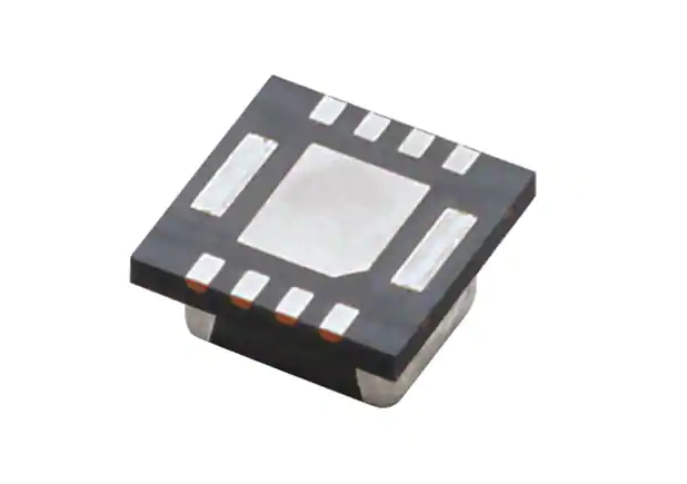
Murata’s MYR series are the PicoBK™ DC/DC converters that integrate a coil and a control IC. The ultra-small form-factor measures 2.5 mm x 2.0 mm x 1.0 mm. The MYR series is significantly smaller than discrete solutions. In most cases, these modules occupy less than half the footprint of the same solution implemented with discrete components.
These DC/DC converters achieve high efficiency, low noise, and high heat dissipation. The devices are designed for a 2.5 V to 5.5 V source such as a Li-ion battery. The input voltage of the MYRGC series is up to 36 VDC and suitable for battery applications to industrial applications. The typical efficiency of the MYRGP is 93% at 5.0 VIN / 3.3 VOUT. The control method can be selected fixed, PWM, or PFM/PWM auto switch.
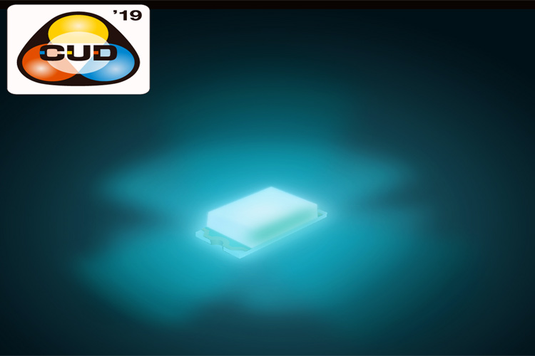
ROHM recently announced the 1608-size high accuracy blue-green chip LEDs, SMLD12E2N1W and SMLD12E3N1W. These products support the adoption of Color Universal Design (CUD) in a variety of applications, such as fire alarm system indicator lights, industrial equipment warning lamps and public transportation information displays.
Color is considered to be one of the most important means of communication and is used in a variety of ways – daily. However, approximately over 200 million people with P-type and D-type color deficiencies around the world find it difficult to distinguish between red and green, possibly resulting in information being inaccurately conveyed – depending on the combination of colors used. Furthermore, since color vision can vary from person to person, it is difficult to perceive how different people see certain colors, which can be very inconvenient and also problematic as other people may not notice this deficiency.
As a result, there is a growing need in the society to implement Color Universal Design that takes into account the various types of color vision in order to deliver information accurately to as many people as possible. ROHM succeeded in developing blue-green chip LEDs with special wavelengths. These products are ideal for implementing Color Universal Design in a wide range of devices, utilizing a vertically integrated production system from the element fabrication stage and leveraging ROHM’s strength thorough quality control.
The SMLD12E2N1W and SMLD12E3N1W are the first* 1608 size LEDs to be certified by the Japanese NPO (Non-Profit Organization), Color Universal Design Organization (hereafter referred to as CUDO) – making it possible to achieve color schemes and designs that can be easily discernible by everyone, including those who cannot distinguish differences in color.
*Based on ROHM’s investigation as of June, 2020.
In addition, adopting a new resin allows ROHM to significantly extend the LED lifetime while reducing the degradation of light intensity compared to conventional epoxy resins and improving the mold strength compared to the silicone resins while providing superior reliability. ROHM also offers AEC-Q102 qualified products that ensure worry-free use in automotive systems and industrial equipment demanding extreme reliability.
GuRu Wireless, a developer of mmWave wireless power solutions, announced the availability of its new evaluation and development kit. The new kit was developed to facilitate testing, evaluation, and proof-of-concept designs, all of which is based on the company’s proprietary, 24GHz, smart RF lensing technology.
Further, the kit can power devices over-the-air from three feet and further.
“GuRu received incredible feedback on prototypes unveiled earlier this year at the Consumer Electronics Show and is now excited to empower partners and OEMs for innovating products for staying powered and connected in meaningful ways,” said CEO of GuRu Wireless Florian Bohn, in a press release. “Via our latest evaluation kit, partners can assess potential use case scenarios and implement wireless power for desired applications.”
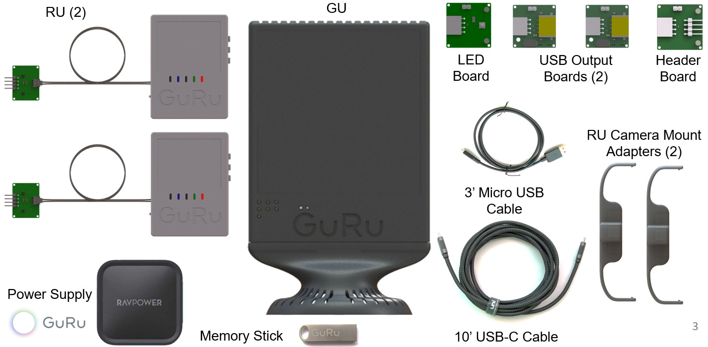
The eval kit for wireless power transmission over-the-air contains the following per the release:
Transmitter: For desktop type environment, in a convenient, small form factor
Power Supply: 15/20 Volt DC for transmitter (industry-standard USB-C connector)
Recovery Unit: 5 Volt DC with a two-pin connector (Extra recovery units available upon request)
Software & Button Interface: For control and monitoring. Updates periodically available
Specialized Software and Hardware: Add-ons and updates available for partners
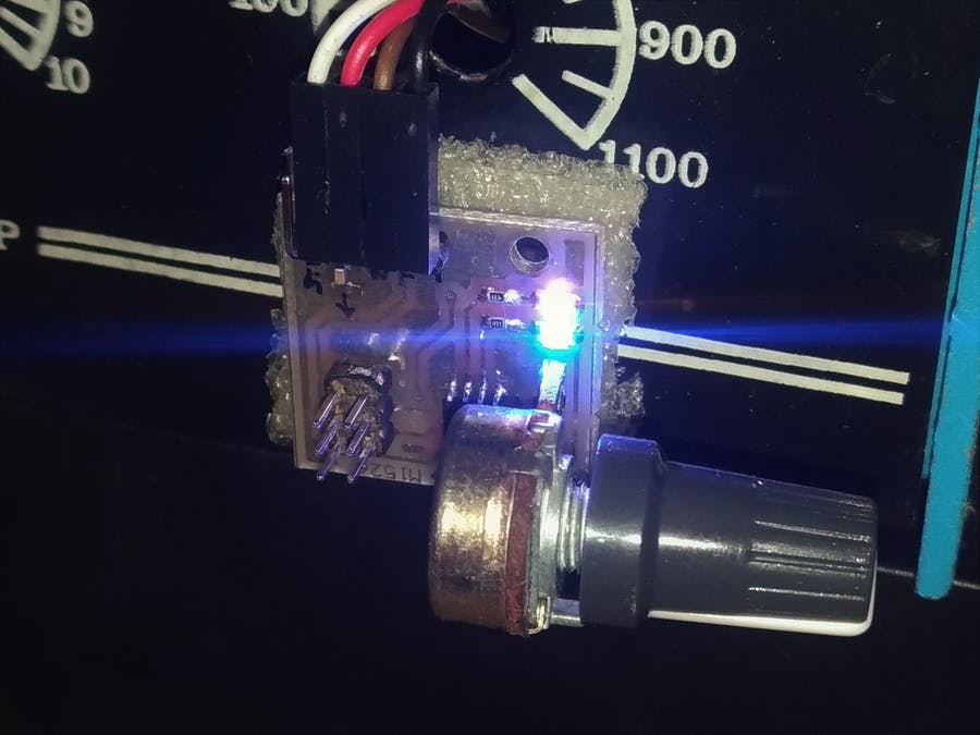
Dimmers provide a way to reduce the power of resistive elements like heaters and light features by changing the waveform of the voltage applied to them. There are different approaches to the development/implementation of dimmers and there are a lot of how-to guides and projects based on them, but the general efficiency of these solutions is usually low due to several reasons. For typical MCU based dimmers, the approach is either; a zero-cross detection circuit to trigger an interrupt on the MCU, or the MCU pulses a Triac with a delay that corresponds to desired power delivery.
The delay approach is quite popular but inefficient as it, in most cases, lacks linearity due to the sinusoidal nature of the waveform of an AC source and leads to the same level of dim, generating different results. To ensure this is not the case for a project they were working on, Tirdad Nejad, and Amir Kazemi, developed an isolated dimmer with linearly corrected output.
Rather than an arbitrary generation of delay time Tirdad and Amir’s project generates delay timings in a way that the partial integration of the sinewave remains the same between dimming steps, thus ensuring linearity.
Some of the components used in the development of the tiny dimmer include; A Microchip – ATtiny13, Triac thyristor, Potentiometer, PC817 optocoupler, an LM1117 based power supply system, and several other passive components.
The project is completely open-source, and all files including schematics, complete BOM, and source code are available on the project’s page on Hackster. More information on the design approach and the logic behind the project is also available there.
Wireless gateways are fast becoming an important part of everyone’s personal network equipment, either as a wireless access point to connect multiple devices to the internet or as a means to provide central firewall functionalities to personal devices. The growth in the demand for these gateways have led to the development of several more efficient and portable versions, but most of them have not been able to achieve the powerful capabilities, possessed by the massive and less portable versions.
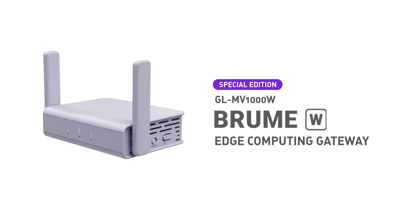
To this end, GL.iNet, a leading developer of reliable network devices, recently announced the launch of their new compact wireless gateway; the “Brume-W (GL-MV1000W” gateway, which, starting at a price point of $120 and weighing just about 115 grams, seeks to compensate for the gap in size and capability being experienced with Wireless gateways.
With dimensions of 88 x 68 x 24mm, the Brume-W wireless gateway is a powerful and yet stable networking system with a high-performance chipset designed to run cutting-edge cryptography at great speed, and a pre-installed OpenWrt that allows in-depth developments for commercial IoT projects. It supports more than 30 VPN services, allows speeds of up to 280 Mbps, and has been applauded by VPN tunnels like WireGuard, for its ”excellent VPN routing experience.”
The pocket-sized Brume-W wireless gateway runs Linux on Marvell’s ARMADA 88F3720 dual-core Cortex A53 processor clocked at 1.0 GHz with a packet processor accelerator.
Some noteworthy features of the gateway include:
1 GB RAM of system memory
16MB NOR flash and 8GB eMMC flash
MicroSD slot that supports up to 256 GB
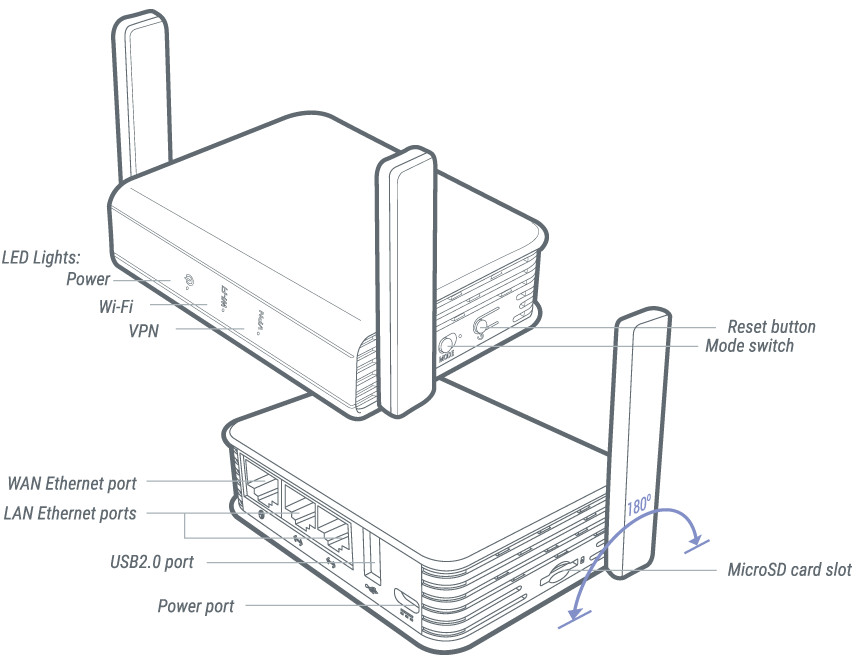
3x Gigabit Ethernet Ports: 1x WAN and 2x LAN
Built-in 2.4 GHz 802.11b/g/n WiFi 4 up to 300 Mbps supported by a pair of external WiFi antennas
Eternal 802.22ac WiFi 5 support via the single USB 2.0 host port
1x MicroUSB 3.0 Type – C port and 1x USB 2.0 host port
Power and Reset buttons, WiFi and VPN status LEDs
5V/3A power supply via the USB – C port, and
Support for 0 to 40 °C temperature range
Brume-W wireless gateway is similar to the GL-AR7505 Slate Router in looks, but it comes with a different processor, more memory and storage.
The gateway features support other software features like AdGuard, Tor, and encrypted DNS with Cloudflare, and also supports as an operating system Ubuntu for people wanting more advanced features.
More details on the features and price of the wireless gateway may be found on Kickstarter while instructions on usage are available on the device’s Wiki page.
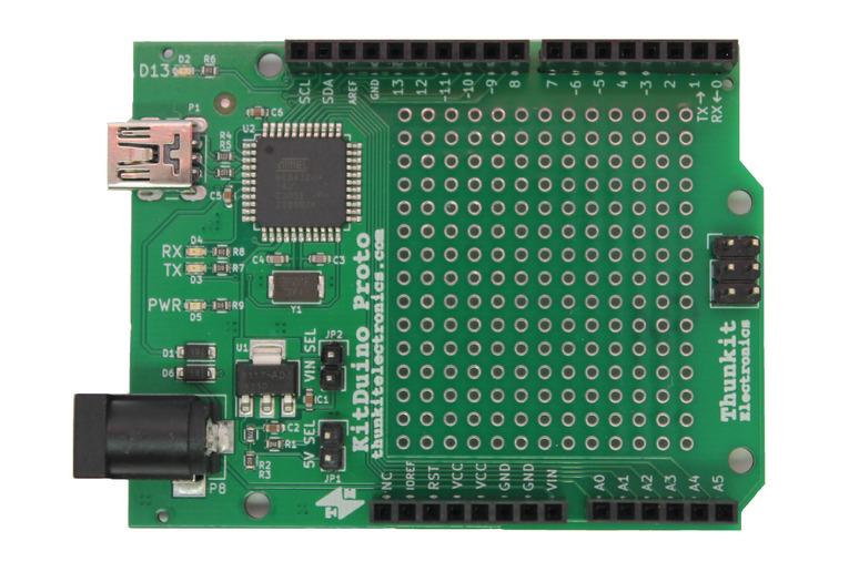
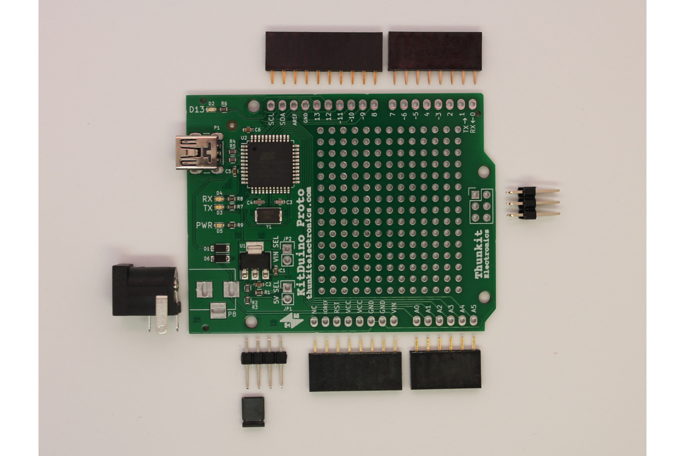
While some may think the era of the Arduino Clones is over, the reverse is the case as more designers are, on a daily basis, releasing a different open-source version of boards that addresses one shortcoming or the other in the Original Arduino board. Sometimes, these reasons behind the clones go beyond the need to fix issues with the original board, but the desire to add new features to it. This is the reason behind one of the latest Arduino board clones; the KitDuino Proto.
Developed by Tindie user; “Thunkit Electronics“, the Kitduino proto is an Atmega32u4 microcontroller-based, development board which was specifically designed for prototyping purposes and comes with a built-in prototyping area.
The Kitduino was designed to provide a flexible prototyping platform for users, merging the MCU and the Veroboard on a single board in a way that gives users the opportunity to develop compact prototypes.
Running at 8MHz, the Kitduino is a low power board with flexible power approaches that enables it to support both 3.3V and 5V voltage operating conditions. By default, the board will run at 3.3V and can be switched to run at 5V by installing a jumper in the ‘5V SEL’ position. However, when powered over USB, the board will run at approximately 3.8V due to due to losses in the regulator circuit. To prevent this from affecting the project’s performance, an external voltage source of 7V or higher can be used, on the boards Vin pin. Leveraging on this, the board will provide a stable 5V rail through the onboard regulator. For projects that are always powered by USB and never see a Vin of more than 5V, the ‘Vin SEL’ jumper can be installed. This jumper directly connects the USB voltage (after Schottky diode) to VCC. However, it’s important to note that Installing the ‘Vin SEL’ jumper and connecting a Vin of more than 5V can cause permanent damage to your board!
The KitDuino Proto is compatible with the Arduino IDE but users need to install Thunkit Arduino Core which can be obtained from the project’s Github page.
The Kitduino is fully open source and the schematics, PCB designs, and firmware, etc., are available on the projects page. However, for users who will rather buy a ready-made version of the board, it is available on Tindie for $12.49 excluding shipping.
More information on the board, pricing, etc., is available on its Tindie page.
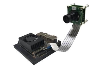
July 15, 2020: e-con Systems Inc., a leading embedded camera solution company, today announced the launch of 5MP camera support for NVIDIA® Jetson Xavier NX™ Developer Kit. The e-CAM50_CUNX is based on 1/ 2.5-inch AR0521, a 5 MP CMOS image sensor from ON Semiconductor.
e-CAM50_CUNX is based on 1/ 2.5’ AR0521 image sensor with an on-board high-performance Image Signal Processor (ISP) chip that performs all the Auto Functions (Auto White Balance, Auto Exposure control) in addition to complete ISP functions. It comes with S-Mount lens holder to support wide range of Lenses. Readily-available with NVIDIA® Jetson Xavier™ NX, e-CAM50_CUNX is the latest and one of the most cutting-edge camera modules of e-con Systems.
“The e-CAM50_CUNX camera module for Xavier NX morphs the Jetson Xavier NX to a edge AI powerhouse for vision. The low noise, excellent image quality, ready-to-use 5MP camera module captures the world into pixel data to be crunched by Jetson’s powerful CPU+GPU combination. The combination of supercomputer performance Jetson Xavier NX and state-of-the-art 5MP e-CAM50_CUNX will be an ideal solution for high-performance AI systems like autonomous mobile robots, smart medical diagnostic instruments, AOI systems and smart city applications”
said Ashok Babu, President of e-con Systems Inc.
Availability
The e-CAM50_CUNX is currently available for evaluation. Customers interested in evaluating the e-CAM50_CUNXcan order samples from e-con Systems’ online store.