CutiePi Tablet For Your Raspberry Pi Project On The Go

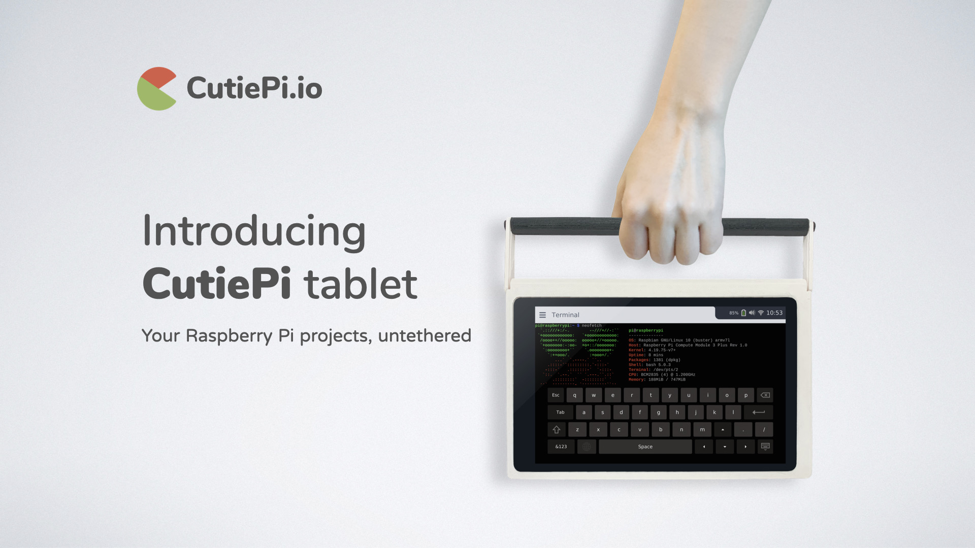
CutiePi is an ultra-portable Raspberry Pi creation kit, in a tablet form factor. It is a tablet that helps you “liberate your Pi project from the desk, and start creating wherever an idea strikes you.” The Taiwanese startup CutiePi, announced details about the 8-inch, Raspberry Pi Compute Module-based CutiePi tablet last year August. They have gone live on Kickstarter and they are almost meeting their $35K goal. At just 12mm thin, CutiePi is probably “the thinnest Pi tablet in the world.” The battery level reading and power management features enable you to carry or recharge it like any other gadgets, and with the touchscreen and battery built-in features, there’s no need to connect a keyboard, monitor or power supply to set up your Pi. About CutiePi the company says :

“We firmly believe people should have control over the technology they use. For that reason, everything about CutiePi, and we absolutely mean EVERYTHING, from the hardware design, firmware, enclosure, all the way to the user interface, is open source.”

This means you can create your own flavor of the CutiePi tablet using the designs. Or build on it to make your next portable project.

CutiePi board design

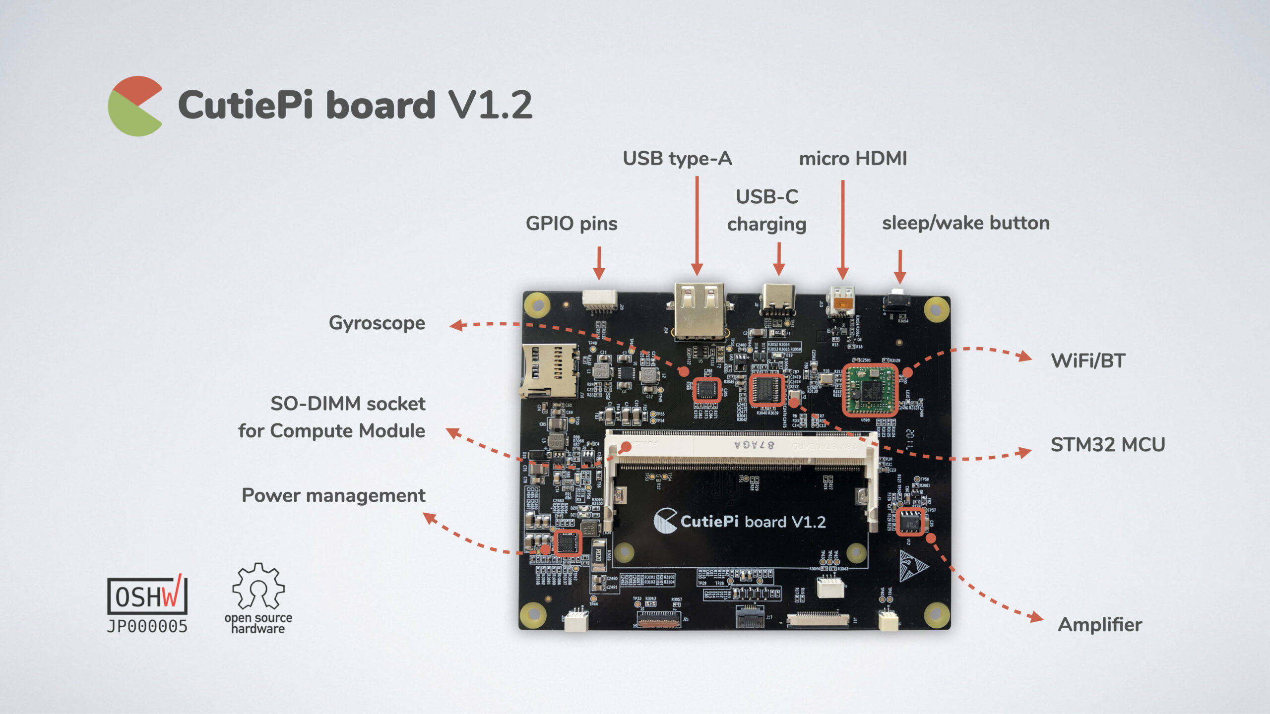
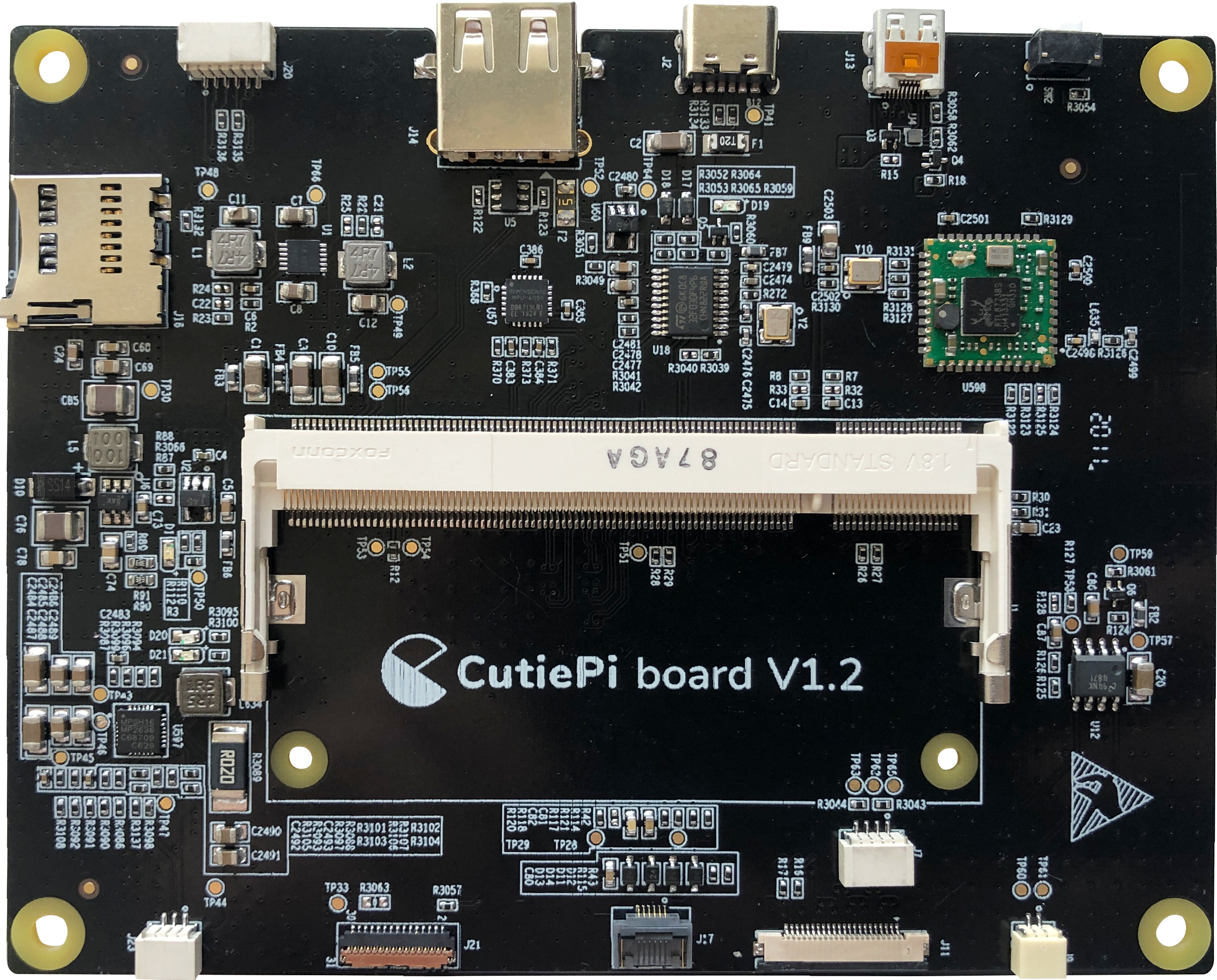
The core of the CutiePi is a custom PCB, the CutiePi board. This CM3/CM3+ compatible carrier board comes with features for portable use and is a proud OSHWA-certified open-source hardware. The CutiePi features the Raspberry Pi Compute Module 3+, which has the same quad -A53 Broadcom BCM2837B0 SoC found on the Raspberry Pi 3B+. The absence of a PMIC, does not enable the 0.2GHz boost to 1.4GHz available on the SBCs, however they have some similarities like the 400MHz VideoCore IV GPU. There is a carrier board by CutiePi that enables a PMIC, and features a STM32 MCU. The CutiePi has similar features to the $25 “Lite” version of the CM3+. It enables 1GB LPDDR2 RAM. There is no flash memory however, it is equipped with circuitry for connecting to a microSD slot, which acts as the major storage connector on the CutiePi. The single USB 2.0 host port can serve as an auxiliary connector for storage.

    CutiePi board

At 213 x 134 x 12mm in footprint, the tablet has an 8-inch, 1280 x 800, IPS screen with 5-point multi-touch capability. This makes it lighter than conventional tablets, and easy to carry around. The tablet is equipped with 5000mAh battery that charges via a USB Type-C port and has a battery life of up to five hours when set to 50 percent brightness, and with Wifi connection. The tablet is further equipped with a micro-HDMI port, 6x GPIO pins, 802.11b/g/n with Bluetooth 4.0, and a handle that also serves as a stand. It also features a 5-megapixel camera, a gyroscope, a 2W speaker, and a sleep/wake button. It provides everything you need on the go: from typing a command in terminal, connecting to a WiFi hotspot, to logging into webpages. For OS support, they say:

“Other than built-in apps and UI designed for the touch screen, we plan to support Raspberry Pi OS desktop and apps via XWayland.”

The CutiePi is available on Kickstarter, and funding ends by Aug 14. The $169 and $179 early bird package is no longer available, but you can get the overslept bird for $189 before the price is increased to $199. Retail price goes for $229. Available also is a $89 package that offers two of the tablet’s carrier boards without the Raspberry Pi CM3+ modules. Shipping should start in Q4 2020. “Shipping fees will be calculated and charged after the campaign. You can confirm the actual costs, including shipping, using Kickstarter’s ”Manage your pledge” function, before finalizing your orders.”

You can find more information may be found on the Kickstarter page and CutiePi website.

nRF52805 Bluetooth 5.2 SoC features a WLSCP, enhanced for small two layer PCB models

Nordic Semiconductor has announced the nRF52805, which is a microcontroller from the NRF52 series of microcontrollers. Measuring at just 2.48 x 2.46mm, the nRF52805 is the smallest of all the nRF52 series. Despite its small size, the nRF52805 System-on-Chip (SoC) top up the industry-leading Nrf52 Series with an SoC in a WLCSP enhanced for small two layer PCB designs, ideal for cost-constrained utility. The nRF52805 is the perfect alternative for applications such as beacons, disposable medical devices, sensors, styluses and presenters.

The nRF52805 features an Arm® Cortex® – M4 processor, clocked at 64 MHz, equipped with a 192 KB Flash and 24KB RAM, and incorporates wide variety of analog and digital interfaces such as a 2-channel 12 bit ADC, SPI, UART and TWI. The Nrf52805 which is a Bluetooth 5.2 SoC enables Bluetooth Low Energy and 2.4 GHz proprietary protocols. It enables Bluetooth high-throughput of 2 Mbps, transmitting info faster and even more efficient, and Bluetooth channel selection algorithm #2(CSA#2), improving coexistence ad reducing interference. The radio has up to 4 decibel-milliwatts TX power and -97 dBm sensitivity (1 Mbps Bluetooth LE).

Specifications:

  • 64 MHz Arm Cortex-M4
  • 192 KB Flas + 24 KB RAM
  • Bluetooth Low Energy
    • Bluetooth 5.2
    • High-throughput 2 Mbps
    • Channel selection algothrithm #2
  • 2.4 GHz proprietary protocol support support
  • Ultra-low-power 2.4 GHz multiprotocol radio
    • +4 dBm TX power
    • -97 dBm RX sensitivity
    • 7 mAin TX (4 dBm)
    • 4.6 mA in TX ( 0 dBm)
    • 4.6 Ma in RX (1 Mbps)
    • Integrated balun with single-ended output
  • SPI, TW, UART
  • 2-channel 12-bit ADC
  • Integradted DC/DC regulator
  • 0.3 µA in System OFF
  • 1.1 µA in system ON with 24 KB RAM retained and RTC running
  • Optimized for small two-layer PCB designs
    • 2.48 x 2.46 mm WLSCP package
    • Significantly lower cost than four-layer PCB designs
    • Only 10 external passive components
    • 9.5×8.8 mm reference  layout design is accessible giving access to all 10 GPIOs

About the Nrf52805 size, Nordic Semiconductor says:

“The nRF52805 is available in our smallest package, a 2.48×2.46 mm WLCSP, optimized for two-layer PCB designs. This supports designs that are small and very cheap, qualities that are originally a design trade-off, since those small designs originally require four layer PCBs, which have significantly higher cost. We provide a 9.5×8.8 mm reference layout design with all ten GPIOs available, requiring only 10 external passive components (inc. two crystal load capacitors).”

The Nrf52805 is compatible with SoftDevice S112, and will also be supported by SoftDevice S113. S112 & S113 are memory-optimized Peripheral only Bluetooth Low Energy protocol stacks supporting up to 4 connections as a Peripheral at the same time with a Broadcaster.

Nordic Semiconductor has provided a guide on how to use nRF52805 with nRF5 SDK, and you can find it here. Nordic Semiconductor recommends you use nRF52 DK development kit, since it emulates the nRF52805, and it can be used as a starting point for development before moving over to a custom board. More information about the Nrf52805 can be found on Nordic Semiconductor’s website.

Neon Pixels Matrix Display Clock

Pierre @pierremuth.wordpress.com shares his latest project with us. It’s a neon lamp dot matrix clock based on INS-1 tubes. He writes:

As a big enthusiast of glowing neon, I had to do something with the INS-1 (ИНC-1) tubes. Disclaimer: this project is inefficient in many aspects, fortunately plenty of time was available during the 2020 lock-down.

Fortunately, these single dot tubes are still easy to find in large quantities and rather cheap. Made by Gazotron, it seems they buildup a large stock at that time. The INS-1 has the advantage to be small and produce a nice dot due to the lens-style front. Plus its striking voltage is maximum 100V, lower than regular Nixies.

At first I imagined 5×7 dot character modules, such as the TIL305, but bigger. While playing and trying to make a tiny and simple 5V to 100V step-up power supply, I realized how simple it can be. Here we just need to reach the striking voltage and only 0.5mA. As there is yet non-uniformity in brightness between tubes, no strong voltage accuracy is needed. Without the signal generator, it is a diode and a coil, shorted to ground with a transistor at high frequency.

Then comes the idea to mimic the popular serial cascading LEDs, such as the WS2812 or SK6812, the so called Adafruit ‘NeoPixel’.

Neon Pixels Matrix Display Clock – [Link]

FLIR Systems Announces Modified Thermal Cameras Specified for Elevated Skin Temperature Screening

FLIR Systems, Inc. announced modified thermal cameras for fast and safe non-contact elevated skin temperature* screening. The FLIR EST™ thermal screening solutions provide frontline screening at building entries and in high traffic areas to improve safety and help curb the spread of COVID-19. The FLIR Axxx-EST, FLIR T5xx-EST, and FLIR Exx-EST series cameras are designed to simplify the screening process, reducing the burden on screening operators and adhering to recommended social distancing guidelines.

“The new FLIR EST thermal solutions represent nearly two decades of experience designing and manufacturing thermal measurement solutions for skin temperature screening,” said Jim Cannon, President and CEO at FLIR. “These cameras are our easiest cameras to set up and operate to date for skin temperature screening, requiring limited training to begin screening people more quickly and accurately.”

FLIR Screen-EST Mode

The new EST cameras also introduce an enhanced, on-camera FLIR Screen-EST mode, which increases throughput by 25 percent compared to the previous version. To further improve accuracy, the updated Screen-EST mode automatically generates a sample baseline temperature average and compares individuals’ skin temperature against that baseline, reducing measurement uncertainty from natural body temperature fluctuations and environmental effects. This mode can sound or display an alarm when the camera detects an elevated temperature above a set threshold. If the screening mode detects an individual with elevated skin temperature, they should then be evaluated using a medical device such as a thermometer. In addition, the new EST cameras are compatible with the new FLIR Screen-EST desktop software announced earlier in June.

more information: www.flir.com

Clock Oscillator in mini package – Clock in a Can

Most microcontroller implementation these days, use the traditional capacitor + crystal approach to generate their clock, this approach sometimes, however, lead to problems, especially when used in prototyping situations with a breadboard, jumper wires, etc., all of which have an (unknown) inherent capacitance that could lead to the clean 8 or 16MHz signal we desire, becoming noisy. A (now regarded as old school) approach to eliminating this is to use a full-can or half-can oscillator which usually comprises the crystal and other elements of the oscillator circuits. However, with advances in microcontroller technologies relegating the need for these oscillators, manufacturers are discontinuing legacy product lines and it’s becoming harder and harder to find through-hole versions of the full/half can packages.  To give the OG’s another option, Schlae recently developed a breadboard friendly PCB version of the full-can and half-can oscillator package called ClockInACan.

According to Schlae, the ClockInACan is a small circuit board that comes in the form factor of the full-can and half-can oscillators and performs the same exact function as the oscillators.

Some features of the oscillators include:

  • Wide +2V to +5.5V power supply range
  • Logic-level enable pin with internal pullup
  • CMOS-compatible output
  • Selectable divide ratio of 1, 1/2, 1/4, 1/8, 1/16, and 1/32
  • Crystal footprint fits through-hole and many surface mount crystals
  • Pins are breadboard compatible, and also fit in DIP sockets

The oscillators are super easy to use, and all you have to do is provide your own crystal of the desired frequency or a multiple of the desired frequency, and set the three solder jumpers to select the divide ratio.

To make the project easy to replicate, it is designed with readily available components. The basic bill of materials is provided in the table below and all components can be found on Mouser by searching with the Mouser Part Number.

Q Designator Description Mouser Part Number
1 U1 Oscillator IC 513-NJU6311RB2-TE1
1 C1 0.1uF capacitor 603-CC603KRX7R9BB104
0 C2, C3 Optional load caps
0 R1, R2, R3 Divider jumpers
1 R4 0 ohm solder jumper
1 Y1 Crystal
4 J1, J7, J8, J14 PCB pins 575-0542000150000

The project is entirely open source and all the documents including schematics and PCB fab files for both the full-can and half-can oscillators are provided on the project’s Github page.

Dual USB Host/Hub Output with Constant Current Limit/Protection

This project has 2 outputs that enable us to power up 2 USB devices simultaneously from an input supply of 12-30V DC. The idea of this project is to have safe power for USB powered devices. The circuit is designed to simplify USB port power delivery based on self-powering 2 port USB HOST/HUB. IC provides two constant current outputs each of 1.1Amp 5V DC, and when any of USB port is overload/short circuit, the fault flag goes from high to low, and the outputs are in constant current mode. The project can be used as a dual-port USB charger in cars or trucks.

Dual USB Host/Hub Output with Constant Current Limit/Protection – [Link]

Dual USB Host/Hub Output with Constant Current Limit/Protection

This project has 2 outputs that enable us to power up 2 USB devices simultaneously from an input supply of 12-30V DC. The idea of this project is to have safe power for USB powered devices. The circuit is designed to simplify USB port power delivery based on self-powering 2 port USB HOST/HUB. IC provides two constant current outputs each of 1.1Amp 5V DC, and when any of USB port is overload/short circuit, the fault flag goes from high to low, and the outputs are in constant current mode.  The project can be used as a dual-port USB charger in cars or trucks.

The project comprises of two parts, a DC-DC converter, and constant current limit switches. LM2576 IC is used as a DC-DC converter that provides 5V 3Amps from an input supply 12V to 30V DC and FPF2303 chip used as dual-channel load switch, consist of dual, independent, current-limited, slew rate controlled P-channel MOSFET power switches. Slew rated turn-on prevents inrush current from glitching supply.

The board provides two jumpers J1 and J2 to enable the outputs. Switch control is accomplished by pulling down the pin ONA/ONB using jumpers. a current limit condition immediately pulls the fault signal pins FLAG-A or FLAG-B low and the part remains in the constant-current mode until the switch current falls below the current limit. The circuit offers current limiting, UVLO, and thermal shutdown protection for each USB port, in the event of an overcurrent condition, the load switch limits the load to the current limit value. The minimum current limit is set to 1.1A. The chip does not turn off the response to an overcurrent condition but remains operating in a constant current mode as long as ONA or ONB are enabled and thermal shutdown or UVLO is not activated.

The project can be controlled using Arduino by interfacing ONA/ONB pins for ON/OFF the output and Flag pins FLAG-A/FLAG-B to check the fault conditions.

Note: The circuit provides constant current outputs, the same board supports other chips details as per bellow

  • FPF2300MX Restart Mode
  • FPF2300MX Latch Off Mode
  • FPF23003MX Constant Current Mode

FPF2300, has an auto-restart feature that turns the outputs again after 504ms if the ON pin is still active

FPF2302, if the constant current condition persists after 10ms, these parts shut down the output and pull the fault signal Pin Flag low.

FPF2303 a current limit condition immediately pulls the fault signal pin Flag low and part remains in the constant current mode until the switch current falls below the current limit. I have tested this board with FPF2303 chip.

 CN1>> Power Input, CN2>> 5V Aux Output, CN3>> Flag-A, Flag-B, CN4>> USB-1 Output, CN5>> USB-2 Output

Features

  • Operating Voltage 12V-30V DC
  • Power LED at Input Supply
  • 2 USB Outputs Each 1.1A Max Load / 5V DC
  • 5V DC Aux Power Out
  • Flag-A and Flag-2 Outputs

Schematic

Parts List

Connections

Photos

Gerber View

Video

LM2576 Datasheet

FPF2303 Datasheet

Fisnar DC50 Digital Dispense Controller

Fisnar DC50 Digital Dispense Controller is a general-purpose, easy to use digital dispenser with a bright 4-digit LED display.It’s user-friendly programming enables a dispense cycle to be quickly created and automatically displayed within minutes.

The DC50 has two modes of operation.

  • Manual Mode: The dispense operation is manually controlled by a foot pedal
  • Timed Mode: Dispenses at the pre-set time for controlled, repeatable shot sizes.

Additionally, the DC50 dispense controller is fully compatible with dispensing both low and high viscosity fluids thanks to its adjustable 0-100psi pressure regulator and vacuum suckback valve. It is a highly reliable and low-cost dispensing solution for both new and experienced users.

more information: www.ellsworthadhesives.co.uk

ON Semiconductor Released the RSL10 Mesh Platform

On Semiconductor released a Bluetooth Low Energy mesh networking solution based on the company’s ultra-low-power RSL10 System-in-Package (RSL10 SIP). The solution has elements needed for the development and deployment of mesh networks.

It consists of two RSL10 Mesh Nodes and a Strata Gateway for connectivity to the Strata Developer Studio. Further, sensing and indicator devices were incorporated into the node hardware, including an ambient light sensor (LV0104CS), temperature sensor (N34TS108), magnetic sensors, LED indicators, and a triple-output NCP5623B LED driver (for color mixing purposes). A built-in battery charger for batteries with Li-Ion or Li-Poly chemistries is also featured.

The company noted that the mesh nodes can be configured to perform different roles and display different functional aspects. The Strata Gateway allows users to evaluate processes to be carried out using the intuitive Strata Developer Studio. Additionally, the cloud-connected software allows for provisioning of additional mesh and supports firmware-over-the-air (FOTA) updates.

For more information, visit http://www.onsemi.com

Use an ATtiny85 to Build Your Own Electronic Compass

At the very heart of any embedded electronics system is a microcontroller. While the ATtiny series of microcontrollers have been around for a while now, they recently started getting noticed on a very high scale as DIYers and professional designers now use them in various projects which ordinarily would have featured a much bigger MCU or an Arduino. The ATtiny85 microchip is a small, affordable, and very versatile 8-bit AVR RISC-based microcontroller that features an 8KB programmable flash memory, 512 Bytes of SRAM, 512B EEPROM, 6 general-purpose I/O lines, 4 channel 10-bit A/D converter, internal and external interrupts and more.

Compared with the microcontrollers like the atmega328p, the Attiny85 has a smaller form factor, which makes them perfect for projects with small overall size requirements, like the electronics compass designed by Instructables user; Rahul7321, for the Instructables Maps challenge.

The tiny compass, which was built around the size of a typical analog pocket compass, comprises of an HMC5883L magnetometer, an OLED display, and the ATtiny85 microcontroller, all connected via the I2C to reduce wiring complexities. The HMC5883L magnetometer is used to sense the Earth’s magnetic field and the data obtained is processed by the Attiny85 and displayed on the tiny OLED in a manner similar to that of the analog compass.

Describing the project and the choice of the ATtiny85 microcontroller, Raul mentioned that the major challenge for the project was to maintain a small form factor, but using the ATtiny85 microcontroller which has just 8kb of programmable flash memory also meant they needed to reduce the size of the firmware. This was achieved by leveraging the I2C protocol in such a way that, it not only reduces the physical form factor but also helps keep a small code footprint.

A more detailed list of components used in the development of the project, asides from the ATtiny85 is provided below;

  • An HMC5883L Magnetometer
  •  3.7V 300mAh LiPo battery
  • A self-locking square button switch
  • 2 parts of a 3D printed case
  • A 0.96” SSD1306 128 x 64 I2C OLED display
  • 2x PCB of dimensions 17mm x 10 mm and 13mm x 18 mm), and
  • A micro USB 5V 1A Lithium battery charger.

One additional cool feature of this project which you might find handy for any other project you design is the charging mechanism, which is implemented in such a way that the user need only place the device on a platform to charge it.

The project is completely open-source and all information you might need to build your own, from schematics to firmware and a step-by-step build guide are all available on the project’s instructable page.

TOP PCB Companies