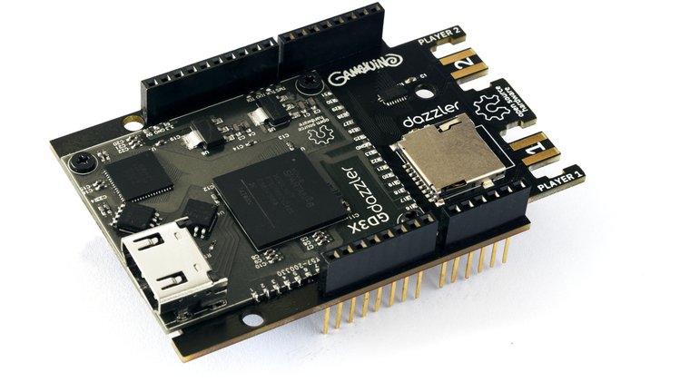
Following the general success of the first version of the Gameduino, an Arduino Shield which allowed users to connect devices like VGA monitors and speakers to the Arduino, to create high-quality sprite/tile-based video games, James Bowman‘s excamera released improved versions of the device with built-in screens and graphics processors which were widely accepted within the open-source gaming communities. Spurred by these successes and the desire to provide users with a shield that reflects current technology realities, excamera recently announced the launch of a new version of the shield; the Gameduino 3x Dazzler.
A totally open-source, and hackable audiovisual platform, the Dazzler shield comprises of a BT815 GPU, a Xilinx Spartan-6 FPGA, an HDMI port, and two Wii Classic ports that give users the experience of a plug-and-play game console.
The combination of the BT815 GPU and the Xilinx Spartan-6 FPGA provided all that was needed to achieve the 1280×720 (full 720p) video (and sound) output over HDMI. In addition to this, the shield features a memory card slot which could house memory card on which game assets like sounds, images and sprites could be stored.
Some highlight features of the dazzler include:
GPU: BT815
FPGA: Xilinx Spartan-6
Video output: 24-bit HDMI at 1280×720 (720p) with audio
Storage: microSD slot
Extra input: two Wii Classic controller ports
Programming: Arduino and CircuitPython, with lots of samples
Console output: built-in with ANSI support
Open source: full stack: hardware, firmware, and software
According to James Bowman,
“the Dazzler is ideal for game designers using Arduino or CircuitPython, makers who want rich, responsive data and text visualizations, and perfectionists who want excellent video output for their Arduino project”.
The dazzler is totally open source, so all project resources including schematics and firmware will be made available.
The project is currently being prepped for a crowdfunding campaign on Crowdsupply. You can sign up on the project page to receive updates and be notified when the project launches.
In the continuity of the Voltage Sources tutorial, we present in this article the Current Sources, which are the second type of electric sources we will look at.
Similarly to what has been done for the voltage sources, we will first introduce the concept of ideal current sources where their particularities and characteristics are discussed.
In real circuits, however, ideal current sources cannot be found as some paradox and impossibilities appear with this model. We distinguish these practical sources as real current sources and we will see what are their differences with the ideal model. The interconnection rules between two or several current sources are also discussed further in the same section.
Finally, the last section details the dependent current sources which are voltage or current-controlled current sources.
Presentation
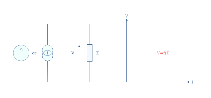
An ideal current source is a device that can supply a constant and stable value of current regardless of the voltage that must be provided to a specific output load. The ideal current sources are represented by a double circle or an arrow within a circle such as illustrated in Figure 1 below:
fig 1: Ideal current source supplying a load of impedance Z (left) and its associated voltage/current characteristic (right)
The characteristic of an ideal current source is sometimes represented I=f(V) as the representation above in Figure 1 is, strictly mathematically speaking, not a function but a distribution.
Real current sources
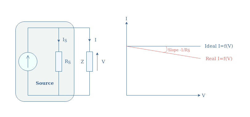
The internal power losses that take place in a current source can be modelized by a resistor (RS) associated in parallel. The I/V characteristic is not anymore flat but, such as for voltage sources, is corrected with a slope of value -1/Rs such as illustrated in Figure 2:
fig 2: Real current source supplying a load of impedance Z (left) and its associated current/voltage characteristic (right)
We can note that an ideal current source is equivalent to a real source which resistance RS tends to +∞ (open circuit).
Connection rules
In this subsection, we highlight the fact that some connection rules are necessary to keep in mind when integrating current sources in a circuit.
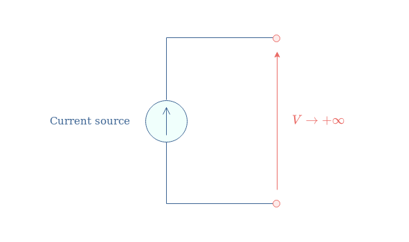
First of all, the terminals of a current source must not be placed in an open circuit:
fig 3: Current source in open circuit, forbidden connection
The resistance of an open circuit is +∞, when the source provides a current that is not equal to zero, the voltage quantity tends to +∞, which is not possible. In practice, the voltage will increase until its breakdown value, forcing the air/vacuum between the source terminals to become conductive. This phenomenon often leads to the destruction of the source or at least one of its components.
Moreover, the series connection of two or many current sources is also proscribed, even if both sources supply the same current value.
fig 4: Current sources in a series configuration, forbidden connection
The reason why this type of connection is not allowed is that an equivalent circuit cannot be predicted: will the sources add, or only one will effectively work?
The current in a branch of a circuit can only take one value, there cannot be an overlay of many currents.
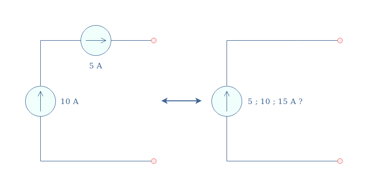
Finally, the parallel association of current sources is absolutely allowed and recommended to obtain a higher output current:
fig 5: Current sources in a parallel configuration, allowed connection
As shown in the second circuit in Figure 5, the values can also be subtracted if one of the sources is oriented in the opposite direction.
In a parallel configuration, the output current is the algebraic sum of the current sources involved in the supply process.
Dependent sources
In the previous sections, an independent current source has been presented and their value is fixed and depends only on the source’s design.
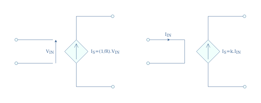
The current value of dependent current sources can be tuned with an external parameter. There are two types of dependent current sources: Voltage Controlled Current Sources (VCCS) and Current Controlled Current Sources (CCCS). In a circuit diagram, current dependent sources are symbolized by an arrow shape (in the direction of the current) surrounded by a diamond pattern:
fig 6: VCCS (left) and CCCS (right)
Voltage Controlled Current Source
For this type of dependent current source, the nature of the input (voltage) is different than the output (current), the linking factor is labeled σ=1/R and represents a conductivity in Siemens (S) or Ω-1.
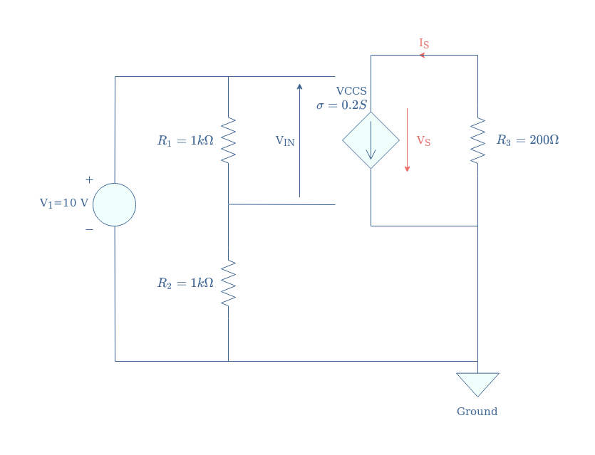
We illustrate what a simple circuit containing a VCCS can look like in Figure 7 and show how to compute its input.
fig 7: A VCCS circuit
Since the voltage source V1 supplies a voltage divider 1 kΩ/1 kΩ, the input of VCCS is given by VIN=V1/2=5 V. Since the gain of the VCCS is 0.2 S, the output current of the dependent source is IS=0.2×VIN=1 A. The output voltage is simply computed by applying Ohm’s law to the resistor R3, we obtain VS=IS×R3=200 V.
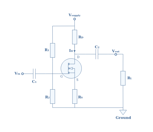
An example of VCCS is the MOSFET amplifier which is a voltage-effect-based transistor:
fig 8: Example of VCCS, the MOSFET supplies an output load RL
As a VCCS, the MOSFET amplifier takes as input a voltage known as gate voltage and delivers an output current known as drain current.
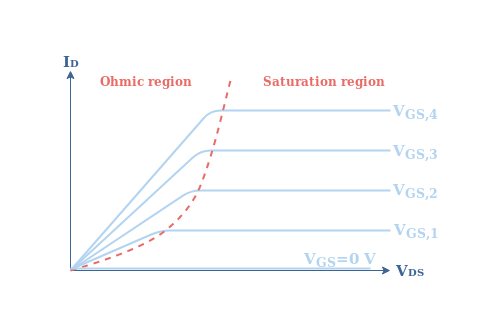
We can affirm that a MOSFET is indeed a current source after looking at its characteristic ID=f(VDS):
fig 9: Output characteristic of a MOSFET
Depending on the command gate voltage (VGS), the characteristic of the MOSFET amplifier becomes flat after a certain value of the output voltage VDS. This characteristic in the saturation region is typical for a current source.
Current Controlled Current Source
In the case of CCCS, both the input and output are of the same nature (currents), the gain is, therefore, a dimensionless quantity labeled k.
We illustrate again a similar circuit that integrates a CCCS in order to clarify how to retrieve the output quantities:
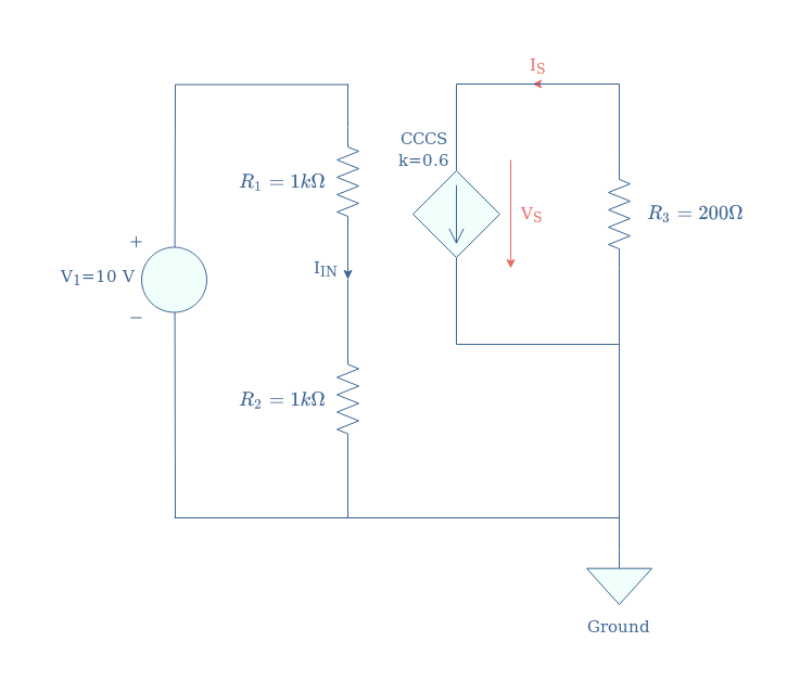
fig 10: A CCCS circuit
The input current controlling the CCCS is here given directly by Ohm’s law: IIN=V1/(R1+R2)=5 mA. The output current is obtained by multiplying the input current by the gain k, IS=k.IIN=3 mA. Finally, the output voltage is again given by applying Ohm’s law to the resistor R3, VS=IS×R3=0.6 V.
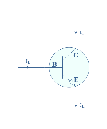
Examples of CCCS are bipolar junction transistors (BJT)-based amplifiers, the reader can refer to the tutorials about Common Emitter Amplifier and Common Collector Amplifier in order to get more details.
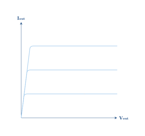
Figure 11 is a plot of the output characteristic in the collector branch (C) for several command base currents (IB):
fig 11: BJT I/V characteristic
We recognize again a flat I/V function after a certain value of voltage, typical for a current source, exactly such as for the MOSFET amplifier.
Conclusion
In order to conceptualize current sources, we have first presented ideal current sources that are not real devices but rather an ideal construction. Ideal current sources provide a constant and stable output current value regardless of the value of the voltage across the output load. They are identified by a flat I/V characteristic which presumes than an infinite amount of power can be provided.
Real current sources, however, present a light slope in their I/V characteristic in order to account for the internal power losses. The value of this slope is given by the conductivity of the source resistance placed in parallel with the source. The source resistance is not physically present in the device but it is rather a way to explain and simplify the calculations.
Moreover, we have seen that some connection rules must be taken into account when designing circuits that include current sources. Placing the current source in an open circuit and associating in seres two or more sources is not recommended. The parallel association is, however, acceptable since it is a useful technique that can increase the output current.
Finally, we have seen that some special current sources can be controlled by an external quantity of the circuit. They are known as dependent sources and for current sources, two types exist:
Voltage Controlled Current Sources (VCCS)
Current Controlled Current Sources (CCCS)
Typical examples of current dependent sources are MOSFETs (VCCS) and BJT transistors (CCCS).
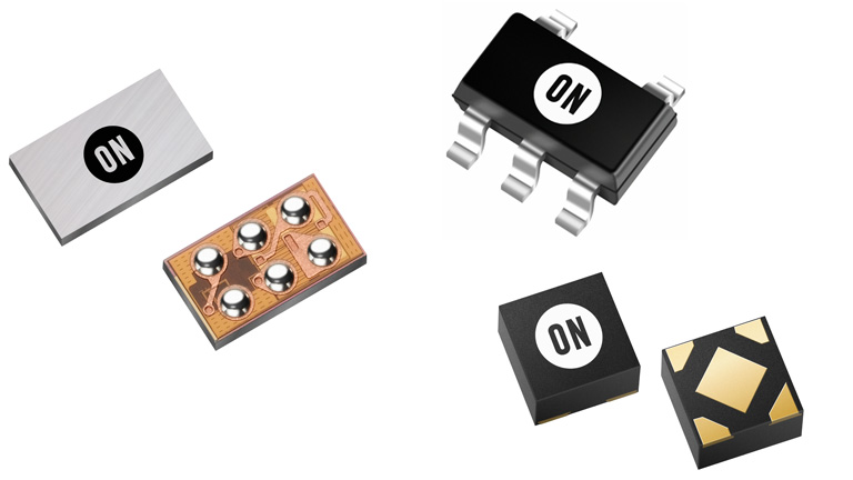
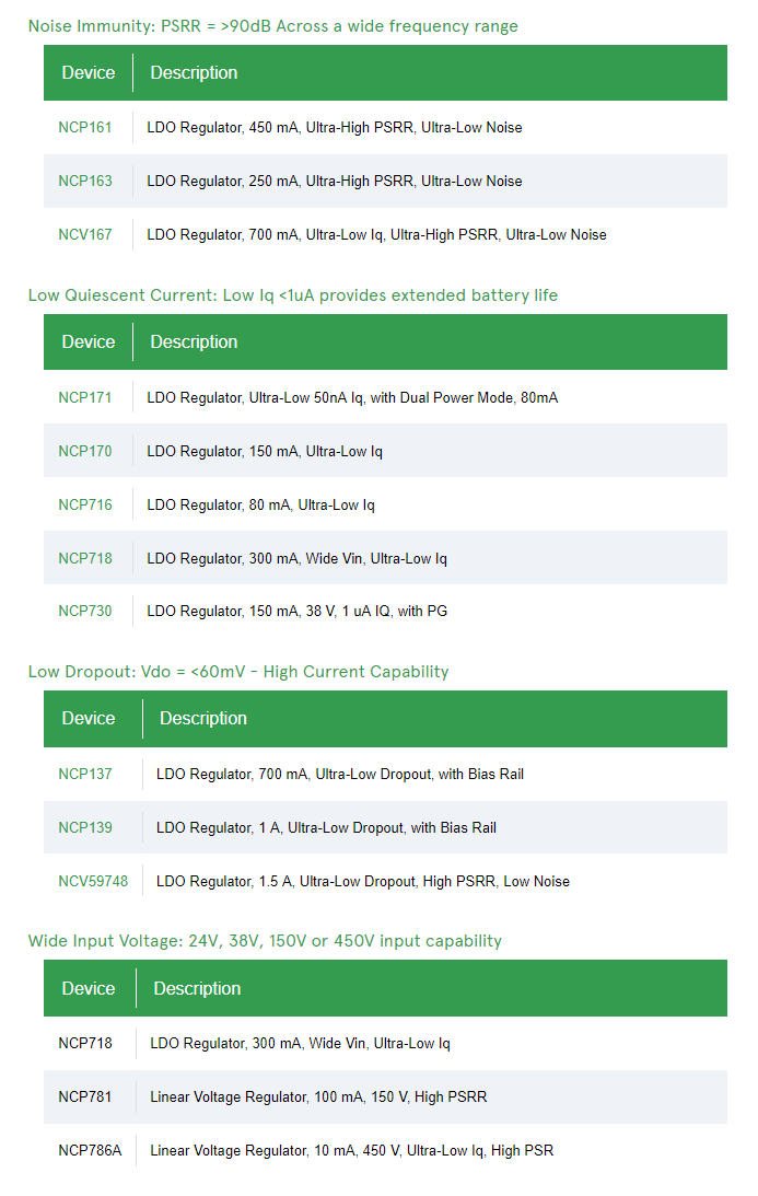
Delivering LDO products in high performance, low power, small form factor solutions to enhance end products
ON Semiconductor’s portfolio of Low Dropout (LDO) Linear Voltage regulators can operate as precision current regulators providing highly stable and accurate voltages with low noise, high PSRR, low dropout, and a very low quiescent current consumption. They provide a wide range of input voltage options with fixed and adjustable output voltage. Available in single and dual output configuration.
Key features
Small size – Industries smallest form factor to performance ratio
Low noise / High PSRR – Market leading PSRR performance
Long battery life – Low Iq to Extend Battery Life
Wide Input Voltage – 1.0V to 700V input available
In addition to their robust design and high reliability, the portfolio offers a variety of protections, making them virtually blow-out proof including overcurrent protection, overvoltage protection, overheat protection, and safe area compensation. Aside from a combination of ideal performance characteristics above, the portfolio is also offered in a variety of package sizes to match specific application requirements for applications such as industrial, consumer, portable & wireless (cameras, tablets, wireless handsets, and smartphones), IoT, and automotive.
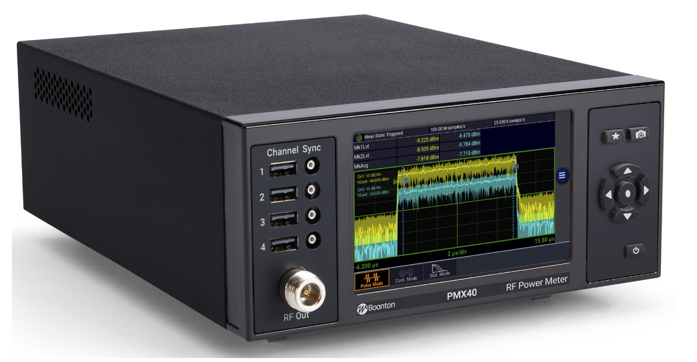
The PMX40’s intuitive, multi-touch display provides a standalone solution for capturing, displaying, and analyzing peak and average RF power in both the time and statistical domains for up to four RF channels.
Saelig Company, Inc. has introduced the Boonton PMX40 40GHz RF Power Meter which combines the utility of traditional benchtop instrument, the flexibility and performance of modern USB RF power sensors, and the simplicity of a multi-touch display. It utilizes the excellent performance and capabilities of the external Boonton RTP and CPS families of USB RF power sensors which offer 3ns rise times and 195 MHz of video bandwidth. They can make accurate measurements virtually independently of signal modulation bandwidth. Up to four USB sensors can be connected for multi-channel power measurements. Independent or synchronized multi-channel measurements of CW, modulated, and pulsed signals provide great flexibility in a benchtop unit without the need for PC control. This makes it ideal for use in ATE/rack-mount setups.
The PMX40’s intuitive, multi-touch display enables fast configuration of the sensors, as well as easy access to measurement and analysis tools, providing a standalone solution for capturing, displaying, and analyzing peak and average RF power in both the time and statistical domains. The meter also incorporates a test source to verify sensor operation.
For simple, intuitive measurements of repetitive waveforms, the PMX40 Continuous Mode of operation provides a numeric display of average, maximum and minimum signal powers. Analysis of fast-rising single pulses or pulses with short pulse repetition intervals (PRIs) requires an instrument with sophisticated trigger and data acquisition capability; with Pulsed Mode, more than 16 pulse parameters can be measured. In Statistical Mode, the PMX40 plots the Complementary Cumulative Distribution Function (CCDF). The CCDF plot shows the rate of occurrence of a specific crest factor for signals, such as those used in 5G, 4G/LTE, and Wi-Fi applications.
Characterization and compliance testing of Wi-Fi and LTE chipsets and devices involves significant challenges for design and test engineers. With multiple-input, multiple-output (MIMO) architectures and channel bandwidths up to 160 MHz, testing is complex, especially when measuring RF power per channel and time alignment between channels. The PMX40 enables packet power measurements to be performed independently on multiple synchronous or asynchronous transmit chains with a common time-base shared among sensors. Design, verification, troubleshooting, and maintenance of secondary surveillance radar (e.g. IFF-based radar) has never been more demanding. The PMX40 can be used to easily, accurately capture SSR waveforms. Markers enable measurements on specific portions of the waveform. As a benchtop meter, the PMX40 provides a standalone solution for capturing, displaying, and analyzing peak and average RF power in both the time and statistical domains through an intuitive, multi-touch touchscreen display. Connecting a PC adds additional software capabilities.
Key Features
Capture/display/analyze peak and average power
Frequency range from 4 kHz to 40 GHz
Industry-leading video bandwidth (195 MHz) and rise time (3 ns)
Industry-leading 100,000 measurements per second
Industry-leading 100 ps time resolution
Synchronous multi-channel measurements (up to 4 channels)
Sensors can be used as standalone instruments
Made by Boonton Electronics, a recognized leader in high-performance RF test instrumentation and sensors, the Boonton PMX40 40GHz RF Power Meter is available now from Saelig Company, Inc. their USA technical distributor.
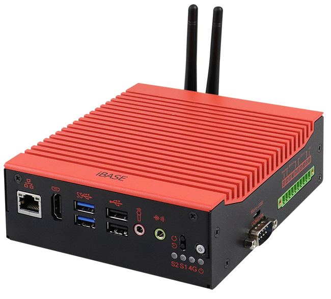
IBASE Technology Inc, a world-leading manufacturer of industrial motherboard boards and embedded computing solutions has revealed its latest EC-3200 AI computing platform that is based on the cutting-edge power-efficient and high-performance NVIDIA Jetson Tegra X2 (TX2) processor. The NVIDIA Jetson TX2 pairs a dual-core Denver 2 alongside a quad-core ARM® Cortex®-A57 processor and provides 256 CUDA cores on the NVIDIA’s advanced Pascalä GPU architecture with up to 1.33 TFLOPS, delivering exceptional AI performance.
Designed to operate under an extended temperature range from -20°C to +60°C, the EC-3200 leverages the integrated GPU-computing power of the Jetson TX2 platform in building edge inference servers to analyze and better manage real-time traffic flow in smart cities or to optimize the efficiency of operational processes in intelligent factories.
“Current edge and cloud-based AI products require better computational and video analytics capability to perform demanding real-time data processing and overcome latency issues,” said Wilson Lin, Director of IBASE Product Planning Department. “The EC-3200 is no doubt a durable solution, especially built with a fanless design for non-stop operation, and takes advantage of the GPU-accelerated parallel processing of NVIDIA Jetson TX2 to handle data-intensive and mission-critical workloads with power efficiency and unmatched reliability.”
With dimensions of 127(W) x 137(D) x 46(H) mm, the EC-3200 comes with 8GB LPDDR4 memory and 32GB eMMC storage on board. To connect to essential peripherals, front I/O interfaces provide a GbE, an HDMI (1.4), two USB 3.0 and two USB 2.0 ports, while a DB9 connector (For RS232 or CAN bus), a Micro USB slot, as well as an external 10-pin GPIO port are located on the right side. The two M.2 expansion slots are designed to support optional SSD storage (M2280) and WAN module (E3042). The system is outfitted with a total of four external antenna ports to enhance throughput and connection reliability in outdoor environments. The OS is based on a custom made Ubuntu 16.04 with Jetpack 3.2.1 and L4T 28.2.
EC-3200 FEATURES:
NVIDIA Jetson TX2, Quad Core, 64-bit, 256 CUDA cores
8GB Memory / 32GB eMMC 5.1 / Single GbE
2x M.2 socket (M2280 & E3042), support SSD/WiFi/BT/LTE
Fanless design with operating temperature range from -20°C to +60°C
Designed for wall-mounting and DIN rail mounting
Custom made BSP based Ubuntu 16.04, Jetpack 3.2.1 and L4T 28.2
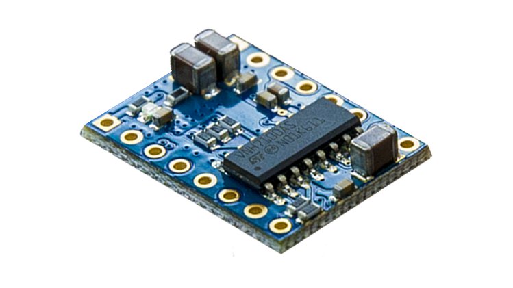
Sam Controllers are set to release Power H Mini V2 Driver for DC Motors. This Power H Mini V2 H-bridge provides a 12A Peak current, inbuilt pulse width modulation, and plug and play drivers. In 2018 Sam Controllers released the open-source Power H Mini H-bridge, which said to enable a lot of flexibility for DC motor applications. The 2018 tiny board had a voltage range of 4V to 28V, also has a peak current of 12A and a pinout and Interface similar to A4988, DRV8825, and other similar versions. Sam Controllers will be launching the new version which is Power H Mini V2 board, which offers extremely low heat resistance, and advanced energy recuperation.
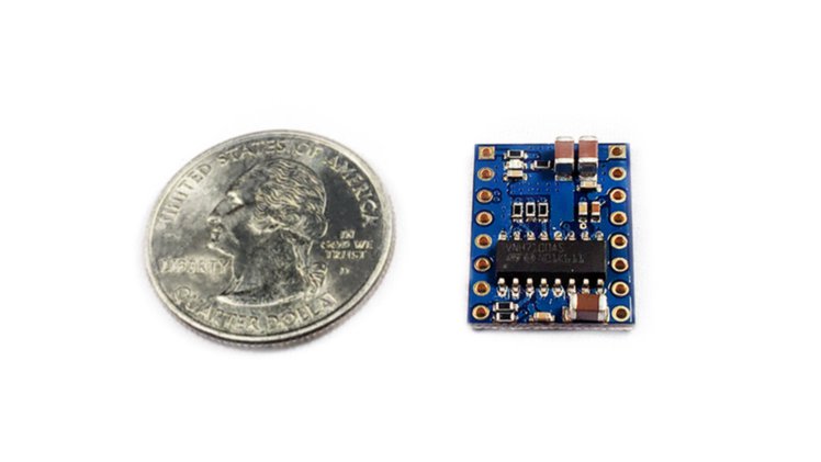
In the area of robotics application, the energy regains means that motors have much sharper, more controlled acceleration curves, and also breaks becomes faster and uniformly without waste of heat on the controller. The Power H Mini retains the peak current of 12A like its older version, it has two-wire control system and inbuilt PWM (Pulse width Modulation). It is made for full-bridge control of a single DC motor and two half bridges can control two motors, additionally, three motors can be controlled using mechanically dependent settings. The board is further equipped with an automotive-grade STMVNH7100AS H-bridge, and it has a similar board size with a 15mm x 20mm dimensions since it is a DC motor driver, it competes in use with H-bridge motor drivers based on the L298 or BTS7960 transistor design which is always produced in a module 2-3x, and it also integrates a dual inflexible high-side driver also having two low side switches.
Tiny size H Mini V2 Driver
Power H Mini V2 Driver Specs includes:
The Power H Mini V2 has a voltage range of 4V – 28V, it has up to 5V logic level on IN pins, having a peak current of 12A, and up to 20KHz for PMW operations.
The Power H Mini board provides overvoltage clamp/protection, heat shutdown and standby mode, and low standby power utilization.
The Power H Mini V2 has MultiSense diagnostic use, analog moto current response, output short to VCC (Voltage Common Collector) detector. Output protection from short to earth and short to VCC, and it can be added in a custom controller design.
Sam Controller is ready to crowdfund the Power H Mini V2 soon, the date of crowdfunding, and the price of the board will be released soon also.
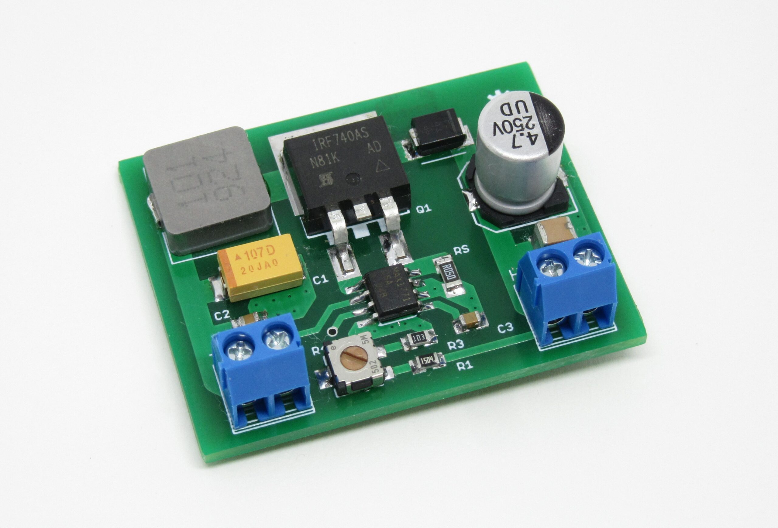
Nixie tubes need about ~180Vdc to light up and thus on most devices, a DC-DC converter is needed. Here we designed a simple DC-DC switching regulator capable of powering most of Nixie tubes. The board accepts 12Vdc input and gives an output of 150-250Vdc.
The module is based on the MAX1771 Step-Up DC-DC Controller. The controller works up to 300kHz switching frequency and that allows the usage of miniature surface mount components. In the default configuration, it accepts an input voltage from 2V to Vout and outputs 12V, but in this module, the output voltage is selected using the onboard potentiometer and it’s in the range 150-250Vdc.
HV Nixie DC-DC Switching Power Supply using MAX1771 – [Link]
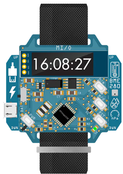
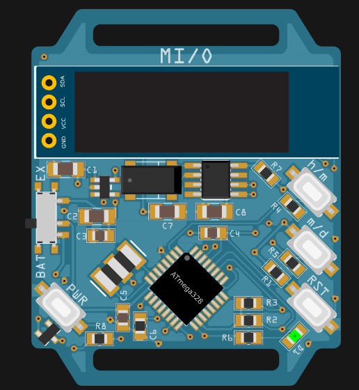
Wristwatches are an integral part of our dressing, and also help us plan our day to day activities, making sure we don’t miss meetings, gym, exams, parties etc. These days, a good looking watch speaks volumes about the wearer, because it’s one of the most noticeable accessories a person wears. We have seen smartwatches taking over the conventional analog watches gradually, due to a host of features smartwatches offer. To this end, Markus Bindhammer has committed to the design and production of his own, slimmed-down “smartwatch” called the MI/O, which looks quite different from conventional smart watches. We can visibly see the components it is made of. It features a Microchip ATmega328 MCU at its core, with its primary aim at functionality rather than fashion.
The MI/O functions by powering down the OLED display and ATmega, rather than dropping the controller into a low-power mode. Unlike other watch designs where the microcontroller is put into sleep mode, MI/O completely switches off everything except the RTC when the watch is not in use. This method of power control is remarkable, and effective, because there is a high level of difference between the lowest of power modes, and actual shutdown in almost entire MCU, so utilizing an external low-power mode of arranging things is ideal. When you turn the MI/O over, you find some extra functionality that enables you to input your own feature sets, with the MI/O acting as the core for any creations you have in mind.
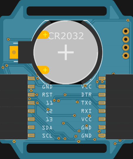
Bottom view
When you look at the rear of the MI/O, it features an array of connectivity, which includes GPIO,I2C, SPI, and the UART of the ATmega can be found on the headers that are visible from the middle of the boards back face. In one of Bindhammer’s demonstration, we see him showing a wing which enables MI/O to be powered externally by a Micro USB connection and a reading light extension. These days, watches are fitted with WiFi, cameras, social media features, and health apps. However, MI/O is built for basic functions.
Bindhammer says:
“The watch itself is finished as far as the hardware is concerned and is in pre-production. However, there is still some work to be done on the software side. In the future I would like to develop more add-ons for MI/O.” About sales, Bindhammer says “I am planning an Indiegogo campaign with MI/O. I’ve teamed up with makerfabs. They will assemble the wristwatch (100 pieces for now). Meanwhile I designed the packaging, a folding box 94 x 94 x 14 mm, 4-color print, glossy look, printed in Germany.”
For now, there are no sources from Bindhammer, but you can find more information on his project page.
A Keylogger, a short form for keystroke logger, is a type of monitoring or digital surveillance tool (software or hardware) that is primarily used to record (log) keyboard keystrokes made by the user of the host computer. They are more advanced in recent times and are sometimes also used to log mouse clicks, touches, etc., typically in a covert manner that ensures the user doesn’t know their actions are being monitored.
While the most popular use of keyloggers is in malicious applications to perpetrate unlawful acts like; collecting personal information like credit card numbers, user names, passwords, etc., legitimate uses for them do exist with, parents using it to monitor their kid’s online activity, ethical hackers/law enforcement agents using it to analyze and track incidents linked to the use of personal computers, and employers using them to ensure employees stay on task.
While software-based keyloggers are more popular because they are less conspicuous, hardware-based keyloggers also have their applications, a good example of which is the employer-employee scenario described above. There are a lot of DIY hardware-based keyloggers on the internet but the recently shared USB WiFi Keylogger by KoKo is one of the most interesting I’ve seen in a while.
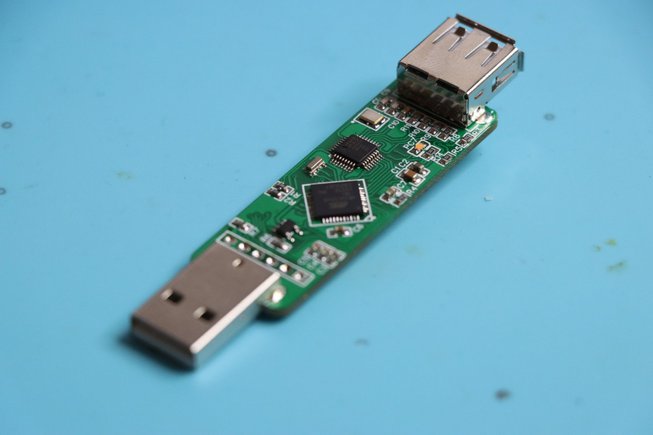
The USB WiFi Keylogger is capable of sniffing keypresses sent from a USB keyboard to a computer and presenting them to the attacker/monitoring entity over WiFi.
The device was designed to be a plug and play device. Simply plug the target USB Keyboard into the female USB port of the keylogger then plug the USB Keylogger into the target computer. After about five seconds, any keys pressed on the keyboard will be logged by the keylogger and passed through to the target computer.
The keylogger is based on the MAX3421EE USB interface and combines an ESP8266 with an Atmega32u4 microcontroller.
To allow external access to the key presses, it is stored in the file system of the ESP8266 which can be accessed over WiFi via the device’s web interface. To access the web interface the monitoring entity needs to be within the range and connected to the WiFi access point created by the USB Keylogger. With this in place, the monitoring entity can navigate to a specified URL and see the logged keypresses displayed withing the textbox on that page. To start a fresh log, the user can clear the previously logged keystrokes using a clear button located at the bottom of the page.
Asides from logging keystrokes, the Masterkey USB WiFi Keylogger can also be used to perform a sort of attack known as Keystroke injection attacks. This can be done via the web interface by navigating to the Live Execute tab at the top of the screen. Through the Live Execute tab, the user can write, run, and save keystroke injection scripts written in ducky script. Users can also save scripts to be used later or upload prewritten scripts to be executed on Masterkey.
For security and customization purposes, the Masterkey has a Settings tab that allows users to customize the appearance of the device and secure the wireless access point. Users are able to change elements like the APN’s SSID, APN’s password, the Channel on which the access point will be broadcasted, and the Hidden elements which will tell the master key whether or not to broadcast the access point.
The Masterkey runs a modified version of spacehuhn’s wifi keylogger code with a few more bells and whistles, and it supports over-the-air firmware update for the ESP8266’s firmware using ElegantOTA.
More information about the Masterkey can be found on the project’s GitHub repo which also holds all the resources you will need to build your own version of the device. KoKo has done quite a lot of work on Hardware keyloggers and you can find more information on diverse kinds of Keyloggers a repo dedicated to them.
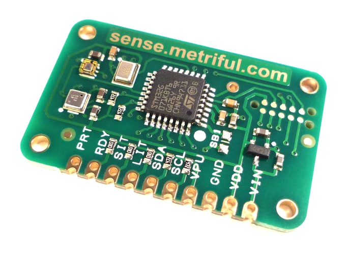
The Covid-19 Pandemic has increased the level of concern people show about the constituents of the air they breathe. While it’s on a different level, it has also translated to a general concern and desire for air quality monitoring, as more people learn about the dangers of air pollution. With innovators, makers, hobbyists, and the likes, this generally translates into a desire to build, and to help with that, Metriful recently announced, via a Kickstarter campaign, a new sensor called Sense.
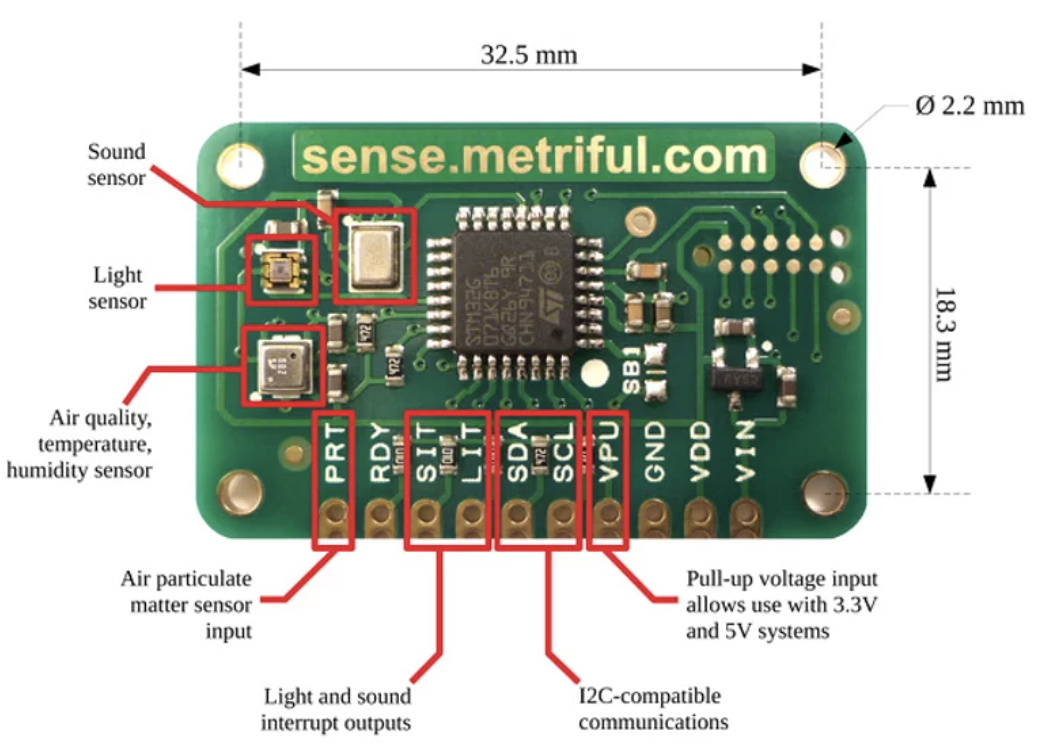
Sense is an integrated Sensor module for indoor environment monitoring. It has onboard, an array of specialized sensors with a high-performance Arm Cortex-based microcontroller which automates sensor management and makes it quick and easy for you to obtain data environment data.
While interests in air quality and environmental monitoring have been on the rise in the past decade, with several solutions, sensors, and modules developed around it, the focus has mostly been on outdoor measurements and applications. However, multiple researches have highlighted the fact that an average person spends over 80% of their lifetime indoors, at the office, in the house, at a restaurants, etc, and areas such, more prone to the dangers of indoor pollution. This is one of the reasons around which Metriful’s indoor sensing solution is built.
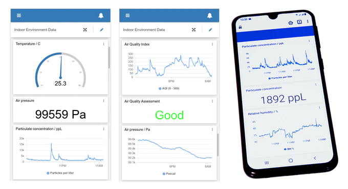
The Sense sensor board, measures eighteen important environmental variables, either on-demand or on a periodically repeating cycle. Some of the environment variables it is able to measure include:
Air quality
Volatile organic compound pollution
Temperature
Air pressure
Humidity
Sound noise
Sound frequency bands
Air particles (with secondary sensor)
Light illuminance
White light level
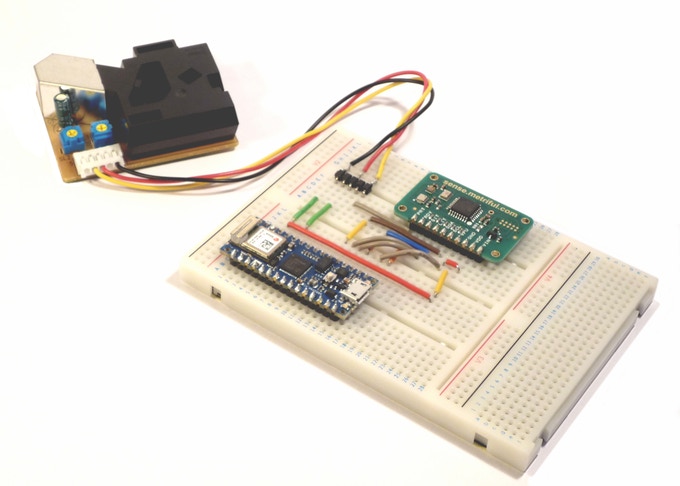
Sense was designed for a broad range of users, from DIY hobbyist to professional designers, as such, it is easy to connect to boards like the Raspberry Pi, Arduino, and thousands of other embedded computers, microcontrollers and development boards. Resources like setup instructions, sample codes, libraries, etc., that could guide you to performing things like basic readings and full cloud-based IoT data logging systems, can be found on the Metriful’s GitHub page.
Thanks to a diverse array of sensors onboard, sense has a wide area of applications but the common and typical ones include smart home automation, Internet of Things, and context awareness.
More information on the sensor, it’s capabilities and the recent crowdfunding campaign can be found on the product’s page on Kickstarter.