We live in a society in which we strive for higher performance and efficiency in everything around us. Computers go to a 7nm process, supercomputers do 148.6 petaflops and electric cars aim for a range of 1000km. From a technological point of view, these evolutions usually come down to a higher energy density, and related temperature hotspots. Traditional solutions such as air cooling with extruded aluminium profile are no longer sufficient. By Jonas Galle (ValCUN)
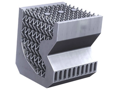
There is a need for more efficient cooling to maintain our technological progress. Cooling with a fluid (water, glycol, …) instead of air provides 10x to 100x better thermal transfer. An optimized design of the heat sink can increase the efficiency by a factor of two or more. Generative optimised design is so complex that they cannot be produced by traditional techniques such as milling, die-casting, extrusion, … The only alternative is an additive manufacturing (AM).
Several metal AM techniques are available today. Main disadvantage of these AM technologies is the production price and speed. These barriers are the main reasons why we don’t yet see them in mainstream applications. Economical serial production of complex heat sinks is the focus of ValCUN. This is done by hybrid manufacturing. Hightech where needed and fast and economical where possible. ValCUN combines traditional production technologies such as diecasting or extrusion with its disruptive metal AM technology.
For the cooling of three IGBT’s a generative design increased cooling performance by 40%. Manufacturing 100.000 coolers with metal additive manufacturing technology known as SLM would not be possible within two year on one machine and would cost more than € 100 per part. Combining diecasting with ValCUN’s AM technology makes it possible to produce this batch in 6 months at a unit price of a factor 3 to 5 less.
Do you want to continue innovating and do you need a cost efficient cooling for serial production, contact Jan at jan.depauw@valcun.be. We select the five most interesting cases, calculate in a partnership how much added value we can create for you, resulting in a free demo part.
Handheld printers are changing what we think we know about getting digital prints on an object/surface. They are allowing users to print whatever they want, from logos to pictures, on whatever surface they want, from clothes to books and merch, in a manner that we would have considered impossible a few years back. While they are super useful, these printers come in a fairly large size, which sometimes affects the kind of surface or object on which they can be used. To take out this little challenge, California based, leading smart printing products and solutions provider; Selpic is about to bring the world to a new height of disbelief, as they plan to unveil a brand new handheld, tiny, pen-like printer called the Selpic P1.
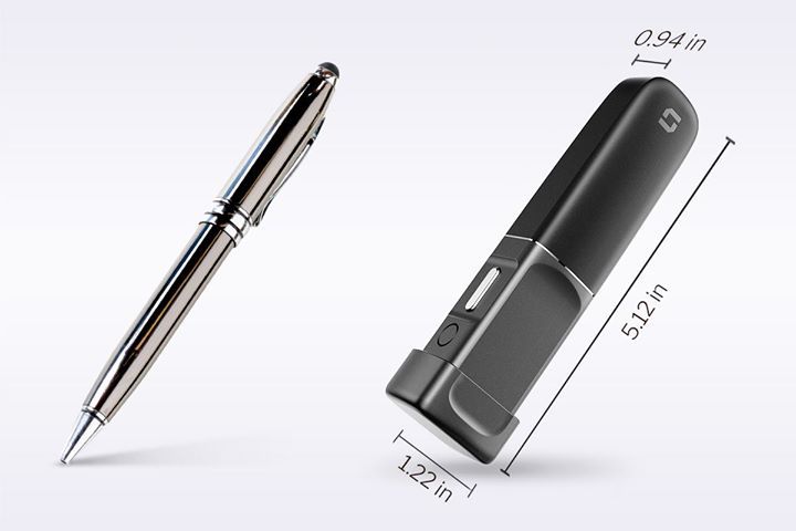
The Selpic P1, which will be unveiled on INDIEGOGO very soon, is the world’s most portable printer pen, small enough to fit in between the fingers and powerful enough to print anything on almost any surface.
Measuring just 5.12 x 1.22 x 0.94 inches with about 0.4 pounds in weight, the pen-like handheld printer is ultra-lightweight and portable enough to be easily tucked into your pocket, bags, or lay on your table without taking up space.
The small size and easy handling associated with the printer make it super versatile and easy to use on almost any object and surface, from Paper, metal, and textiles, to plastics, wood, leather, and other porous materials. The meter is also uniquely powerful, making it possible to print texts, photos, logos, barcode,QR code on these surfaces by simply moving it over the surface.
Built with 600 DPI resolution and adopted advanced water-based ink, the Selpic P1 enables you to print high-quality, vivid, and fade-resistant designs instantly. The Printer has outstanding output levels and is able to print about 90 pages of A4 paper, and can print multi-lines, as well as create prints at variable speed, making it a great option for printing a diverse range of digital elements including logos, images, and complex designs like business cards to mention a few.
To allow users to easily load their designs for print, the reasonably priced ($99.9) printers come with comprehensive print software that works with the device over Wi-Fi in a really simple manner. All a user need do is to download and install the APP on your phone or computer (PC/Mac), upload the design you want to be printed and hit the print button, gently sliding the printer on the surface you want to print on.
To provide users with a reasonable amount of on-time, the Selpic P1 is powered by a 7-volt lithium-polymer battery, which ensures users enjoy an amazing 3 hours of non-stop working time.
Some highlight features of the Selpic P1 include:
Ultra-portable & lightweight
Print anything & anywhere
600 DPI high resolution
90 pages large print capacity
Up to 6 Cartridge colors
3 hours long working time
The small and portable nature of the Selpic P1 makes it perfect for business travel, events, classes, or office applications.
A campaign for the Selpic P1 will be soon launching on INDIEGOGO with the device starting at only $99. There are several other packages planned with associated discounts. You can sign up to get notified when it launches and also to get first option access to the diverse discounts like the super early bird discount of 55% off the $199 MSRP package which will be available to the first 500 backers.
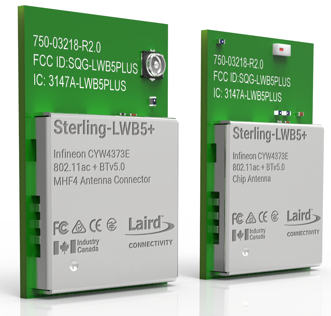
Wireless technologies provider Laird Connectivity has announced a Wi-Fi 5 (802.11ac) and Bluetooth 5.1 module that it says is purpose-built for industrial Internet of Things connectivity through a secure, reliable, and robust feature set. [via]
Powered by the Cypress Semiconductor CYW4373E wireless solution, the Sterling-LWB5+ was intentionally designed for industrial IoT applications where performance, size, cost, and ruggedness are required to deliver reliable wireless connectivity. Careful design considerations were made, says the company, to ensure the Sterling-LWB5+ is painless when integrating into host platforms.
“Our customers span multiple industries that have a diverse set of requirements and a common need we identified was the creation of a true industrial IoT module,” says Jay White, product manager for Laird Connectivity’s Wi-Fi solutions. “We took direct customer feedback and together with Cypress, made purposeful design considerations to ensure that our module caters to industrial IoT devices, is fully certified, and simplifies our customers’ BOM; reducing certification costs and improving time-to-market.”
The Sterling-LWB5+ feature-set includes 802.11ac Wi-Fi and dual-mode Bluetooth, an industrial temperature specification, and a solder-down module form factor that is suitable for industrial devices where vibration and impacts are common. With an integrated PA (power amplifier) and LNA (low noise amplifier) and antenna diversity, says the company, the module ensures reliable connectivity in harsh RF environments.
A Linux Backports package ensures compatibility for a broad range of Linux kernels. The Sterling-LWB5+ is offered as ideal for harsh industrial IoT application areas including rugged handheld devices, industrial IoT connectivity, industrial IoT sensors, and battery powered medical devices.
The module supports the latest WPA3 security standards and will be globally certified to reduce customers’ barrier to entry. Pending certifications include FCC, IC, CE, Giteki, and RCM.
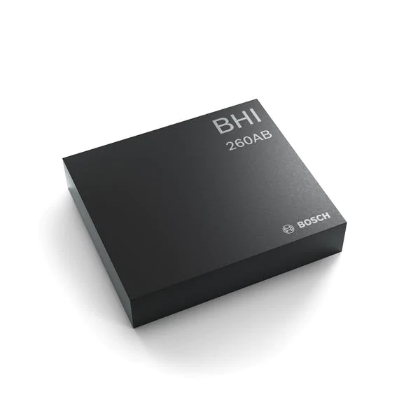
Bosch Sensortec’s BHI260AB ultra-low-power high-performance smart sensor hub with integrated accelerometer and gyroscope
Bosch Sensortec’s BHI260AB is a family of ultra-low-power smart hubs consisting of Bosch Sensortech’s programmable 32-bit microcontroller (Fuser2), a state-of-the-art 6-axis IMU, and a powerful software framework containing pre-installed sensor fusion and other sensor processing software within a small 44-pad LGA package.
The Fuser2 Core is configurable to operate at 20 MHz (Long Run mode) and 50 MHz (Turbo mode). It can boot from a wide variety of hosts, ranging from a small Arm® Cortex®-M0 MCU up to multicore application processors, while it can also run standalone when booting from an attached Flash memory. In combination with its wide connectivity and extendability, the BHI260AB becomes a versatile and ideal solution when it comes to always-on sensor processing at ultra-low-power consumption.
Hardware Features
CPU core
ARC® EM4 CPU with ARCv2 16/32 bit instruction set (up to 3.6 CoreMark/MHz)
Floating point unit (FPU) / memory protection unit (MPU)
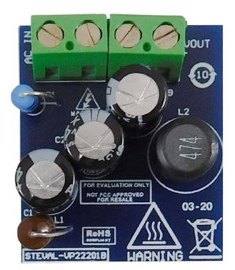
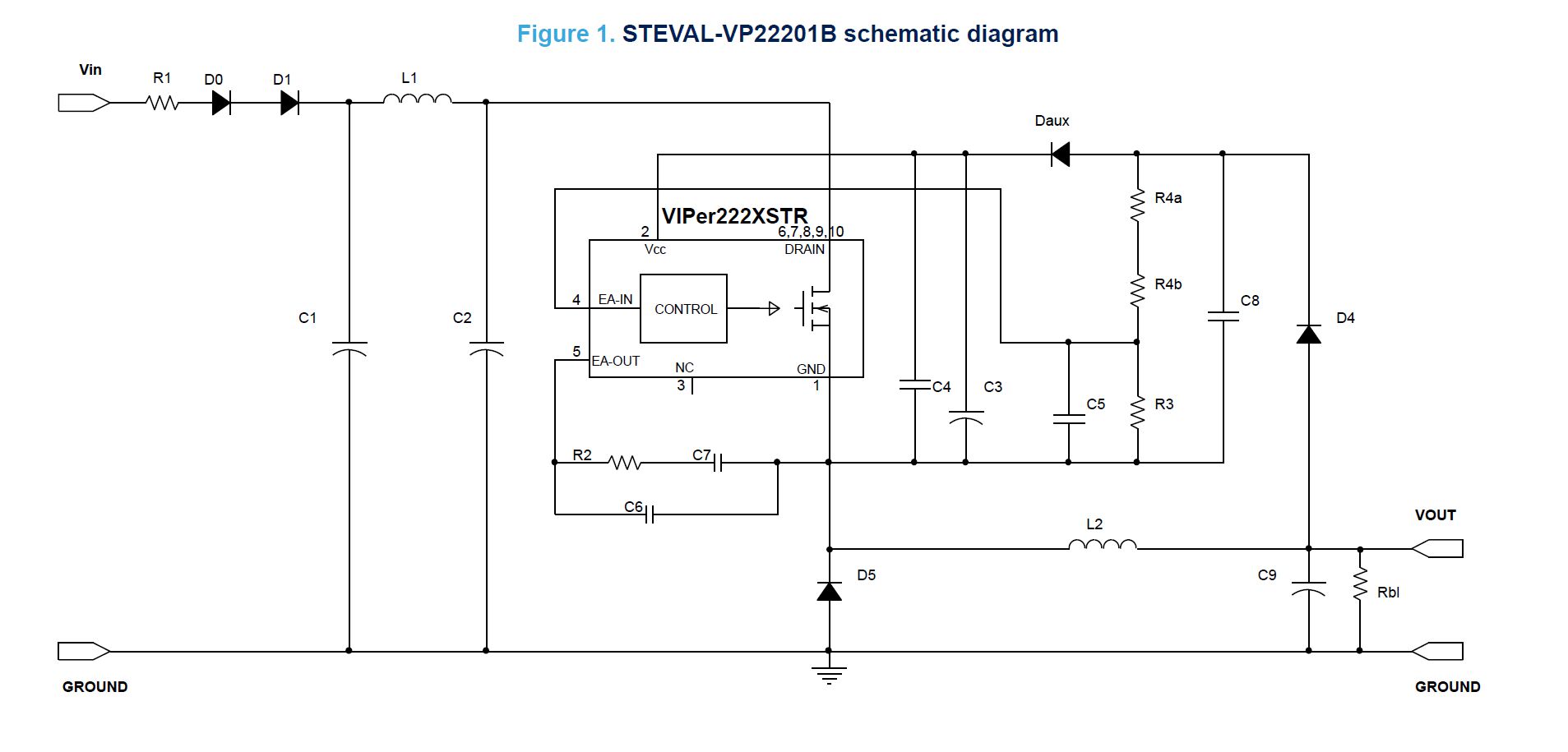
The STEVAL-VP22201B evaluation board implements a 5 V – 1.8 W isolated flyback converter developed for general purpose applications operating from 85 to 265 VAC.
The reference design is built around the VIPer222XSTR offline high-voltage converter from the VIPerPlus family, with 730 V Power MOSFET and PWM current-mode control.
The main characteristics of the evaluation board are its small size and minimal BOM, low stand-by consumption and tight line and load regulation over the entire input and output range. Extremely low consumption under no-load condition is ensured thanks to burst mode operation that reduces the average switching frequency and minimizes all frequency related losses.
Key Features
Universal input mains range: 85–265 VAC
Frequency: 50-60Hz
Output voltage: 5 V
Output current: 360 mA
Very compact size
Stand-by mains consumption: < 18mW at 230 VAC
Tight line and load regulation over the entire input and output range
Meets IEC55022 Class B conducted EMI even with reduced EMI filter, thanks to the frequency jittering feature
RoHS compliant
VIPer222XSTR operates at 30 kHz fixed frequency with frequency jittering to enable compliance with standards regarding electromagnetic disturbance.
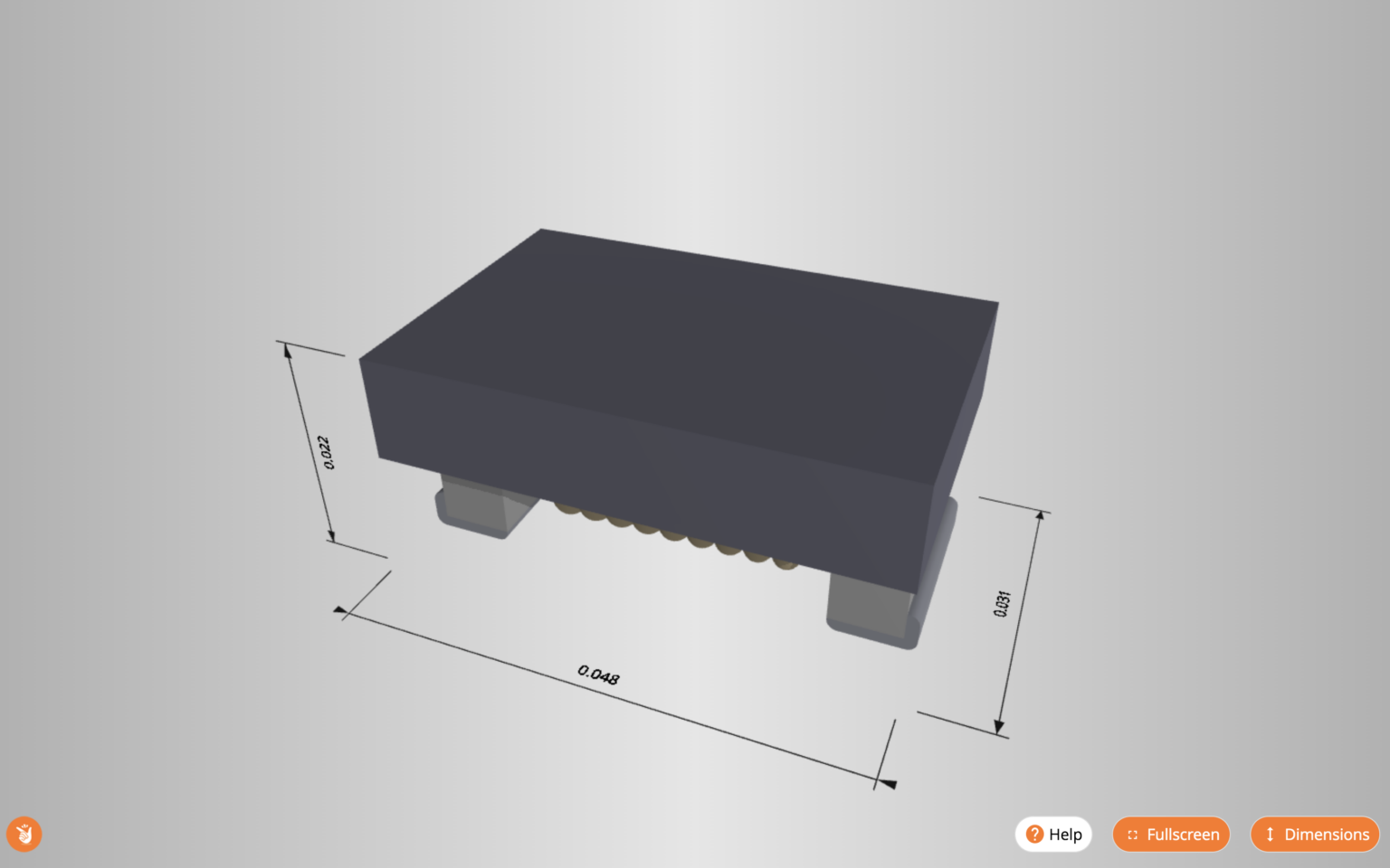
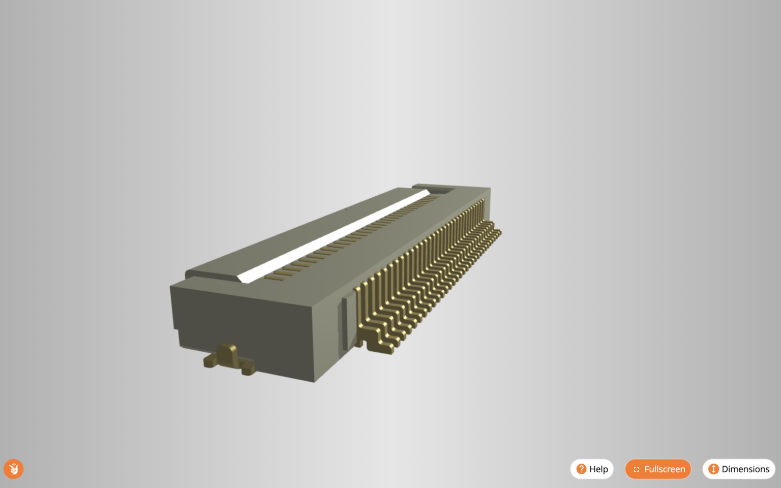
SnapEDA is excited to share that they have launched a new and improved 3D viewer for our parts. It allows engineers to preview 3D models available on SnapEDA before download. [via SnapEDA blog]
They’ve added three key features, based on feedback from our community. First, they’ve added dimensions to the viewer so that engineers can verify key measurements before downloading. This was by far, the most requested feature of our new viewer. Second, they’ve added the ability to zoom in and out to get a closer look at the component’s details. And finally, engineers can rotate the parts to see them from every angle.
Benefits of using 3D models when designing PCBs include, among many others:
Getting immediate visual feedback of your designs, which will aid in identifying issues such as shadowing of components
Confirming clearances between a component and its enclosure, or between other components
Verifying that the component outlines and designators of your parts are correctly positioned
Communicating design specifications – and demonstrating your hard work – to key stakeholders (ex: managers, clients, etc.) through beautiful 3D renderings of your circuit board
What’s new in the SnapEDA 3D model viewer
Dimensions: You can now view measurements of the models. You can enable or disable this feature by clicking on Dimensions in the bottom right-hand corner.
Full-screen view: If you want to take a closer look at the 3D model, click on the Fullscreen button in the bottom right-hand corner. To exit full-screen view, click the button again, or hit the escape key on your keyboard.
Zoom: Zoom in and out on the 3D model using your mouse wheel.
Panning: Pan using your right mouse button and by dragging your cursor.
Check out our new viewer in the 3D Model tab of our any of our parts with 3D models available. Give it a try for yourself by checking out the parts showcased in this post. Make sure to click on the 3D Model tab to see them.
The 3D model viewer is available now on the SnapEDA website and all suppliers’ sites that use the SnapEDA plugin. If you’re a component supplier or distributor interested in adding symbols, footprints, or 3D models to your website, contact us.
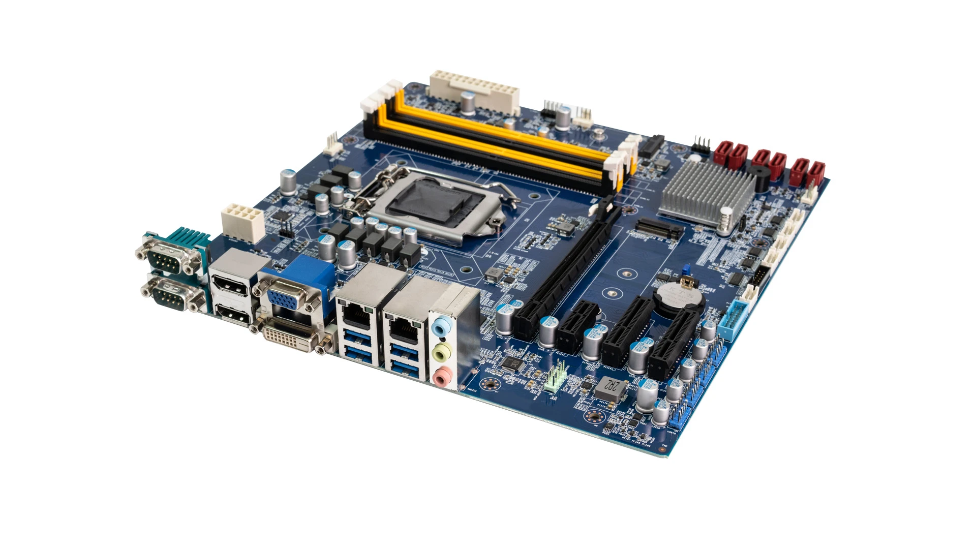
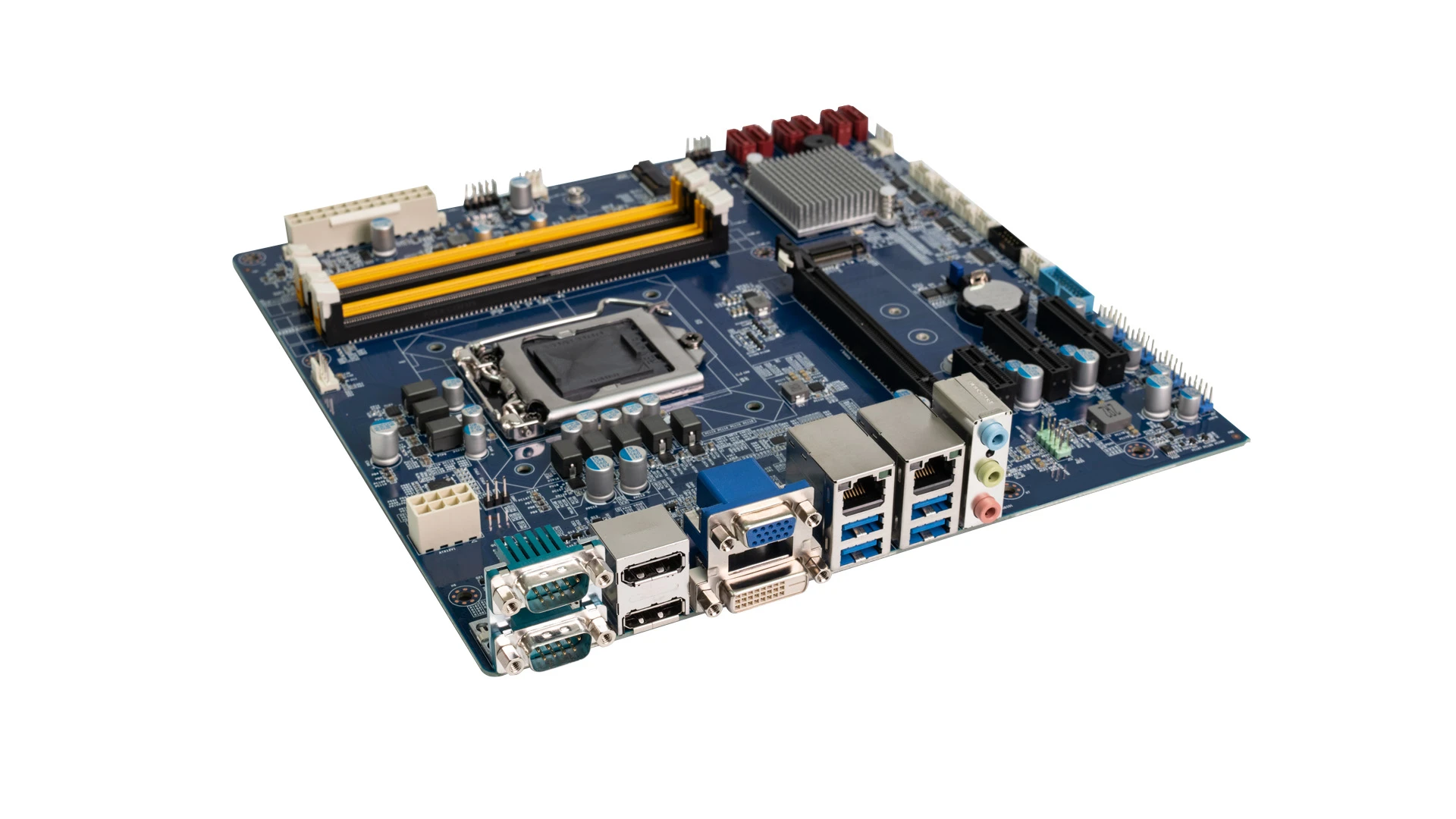
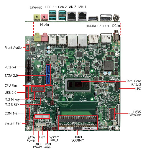
CT-MCL01 MicroATX motherboard Enhanced Power Drives Computing Performance, Reliability, and Security for Industry 4.0 Applications
Premio Inc., an innovating global industrial ODM/OEM edge-to-cloud solutions provider, released its new CT-MCL01 MicroATX industrial motherboard for rugged IoT processing. The announcement marks Premio’s introduction of products supporting 9th Gen Intel® Core™ — codename: Coffee Lake Refresh — processors. The compact, next-generation motherboard carries numerous features that allow system integrators to take advantage of developments in IoT and connectivity technologies for embedded industrial applications.
“This new motherboard helps system integrators easily incorporate a future-ready processing solution into their final configuration of end-user products,” said Dustin Seetoo, Premio’s director of product marketing. “Our CT-MCL01 industrial-grade motherboard was designed to allow machine builders for industrial applications the ability to harness faster processing and connectivity in embedded IoT technologies.”
The CT-MCL01 has a micro-ATX form factor consisting of reliable industrial-grade components with extended product lifecycle support up to 15 years. The industrial motherboard supports Intel® Core™, Celeron, and Pentium processors ranging from 4- to 8-multi-core performance. Its LGA 1151 socket supports Intel’s Q370 chipset to deliver better performance, stronger security and quicker I/O connectivity to expansions and peripherals. Four DIMM slots support DDR4 2666MHz (up to 128GB) for rapid memory frequency speeds
The industrial motherboard contains two M.2 connectors enhancing device connectivity and storage. One connector keyed to the E position can receive a Wi-Fi 6 card for superior network performance. The other, keyed to the M position, serves as a PCIe x4 interface and supports NVMe storage.
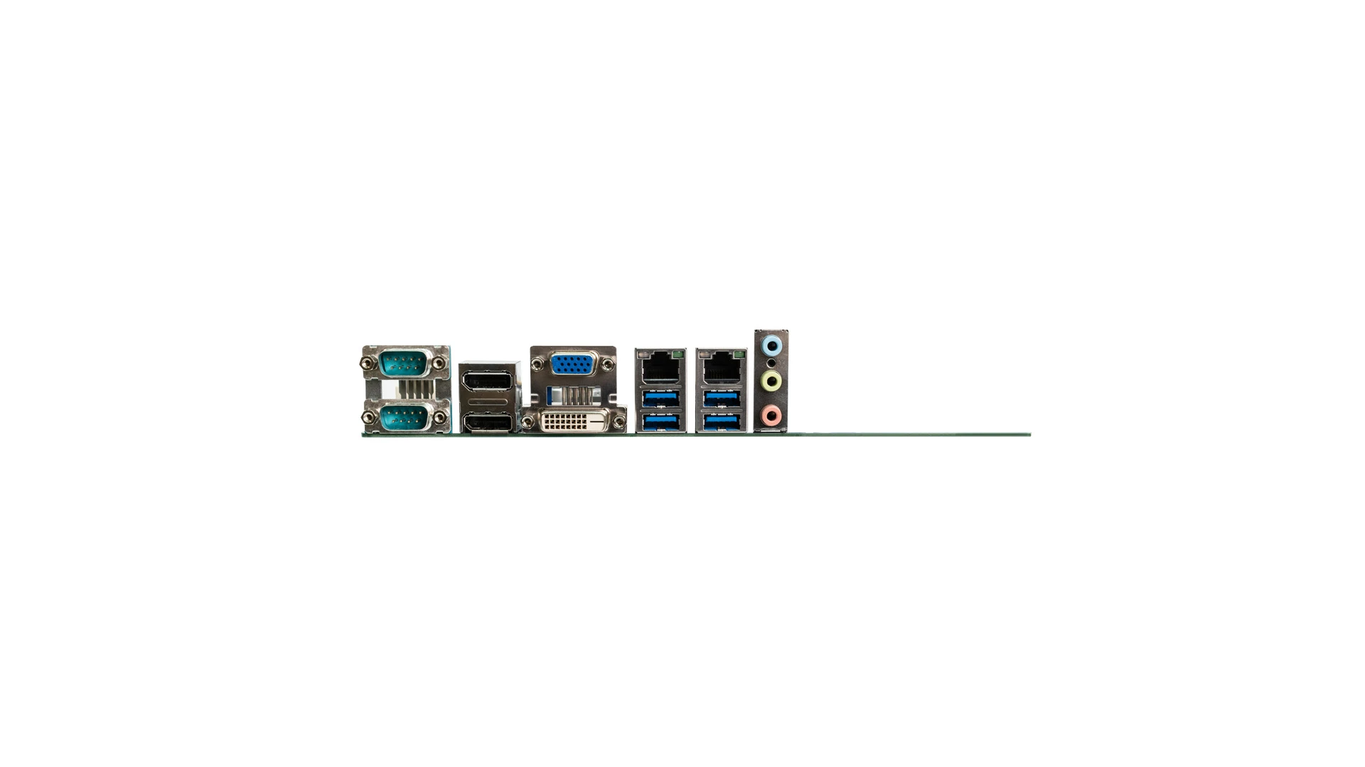
The CT-MCL01 boasts rich I/O and expandability options that bring flexibility and heightened performance to industrial applications. The advanced processing power delivers crisp streaming 4K graphic content to multiple UHD devices via three independent display ports (DP, VGA, DVI-D). The industrial motherboard also features a variety of device connectivity ports: six SATA 6Gb/s buses for mass storage devices, six serial COM (RS-232/422/485) connectors for legacy devices, and 13 available USB ports (USB 3.1 Gen 2, and USB 2.0) for high-speed IoT peripherals. The CT-MCL01 motherboard also offers four PCIe Gen3 expansion slots (one PCIe x16, two PCIe x4 and one PCIe x1) to accommodate dedicated acceleration cards for machine learning and high-speed networking. System integrators and machine builders have the flexibility to populate a wide variety of add-in cards for their industrial applications.
An installed trusted platform module (TPM) counters cybersecurity threats faced in modern industrial deployments. The module delivers boot security and platform integrity at the hardware level to TPM 2.0 standards, preventing malware from affecting critical systems. The TPM root key enables encryption for device applications and data, while also providing password protection authentication to only allow trusted parties access to the system.
The CT-MCL01 MicroATX industrial motherboard was purpose-built to serve the ongoing evolution of Industry 4.0 technologies, especially in terms of reliability. The industrial motherboard’s processing strength and versatility serve as the foundation to robust, future-ready hardware addressing changing demands of industrial computing. Embedded applications focused on kiosks, security and surveillance, transportation, and factory automation can leverage this motherboard for next-generation IoT upgrades.
For more information about Premio’s entire portfolio of industrial computers and other embedded IoT solutions please visit premioinc.com or email sales@premioinc.com to learn more.
In this tutorial, we present in detail the architecture, functioning, and use of an important electronic element known as the voltage source.
We first present the base concept which is the ideal voltage source and an introduction to the alternators and batteries is given since they represent the most common types of AC/DC voltage sources.
Further, we highlight that these elements, like their names, suggest it, are ideal and therefore not found in real circuits, this is why we introduce and discuss the real voltage sources. Moreover, we establish some connection rules to be followed in order to properly implement voltage sources in a circuit.
Dependent sources are detailed in a third section where we will see that some voltage sources can be controlled by a voltage or current input.
Presentation
Alternators
A voltage source is an electric generator, and it produces an electromotive force from a different form of energy. The most common voltage sources are alternators and batteries.
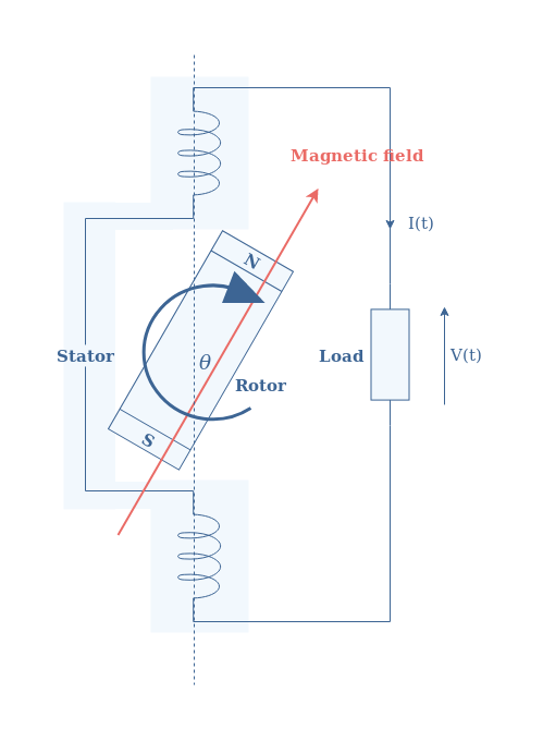
Alternators convert energy by mechanical rotation to produce an AC signal and their functioning, thanks to the electromagnetic induction phenomenon is explained in the Sinusoidal Waveforms tutorial.
fig 1: Architecture and functioning of an alternator
Batteries
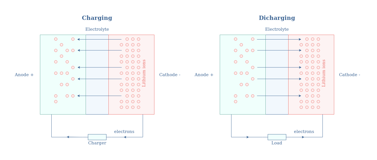
On the other hand, batteries convert chemical energy into a DC signal thanks to a reduction-oxidation reaction. One of the most common types is certainly the lithium-ion battery which function schematic is presented in Figure 2 below:
fig 2: Charging/discharging functioning of a Li-ion battery
Ideal voltage sources
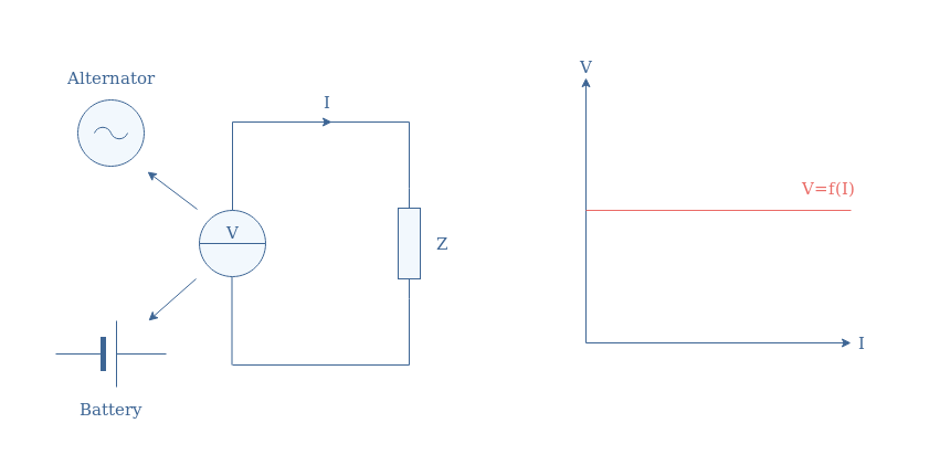
An ideal voltage source is an element that can supply a constant value of voltage regardless of the current flowing through the output load. This definition is both valid for DC or AC voltage sources, in the AC case, it is the RMS value that is kept constant.
The following Figure 3 illustrates how a voltage source is usually drawn in a circuit diagram and its related voltage/current characteristic. Note that no distinction is made between a DC or AC source, the labels V and I can therefore both refer to the DC or RMS values.
fig 3: Ideal voltage source supplying a load of impedance Z (left) and its associated voltage/current characteristic (right)
It is important to remember that ideal voltage sources are characterized by a flat V/I characteristic. The consequence of such a characteristic is that an ideal source can theoretically supply any amount of power (V×I) without any losses.
This affirmation is of course not true, in real sources the power supplied is limited by losses which origins are internal to the source as we will see in the next section.
Real voltage sources
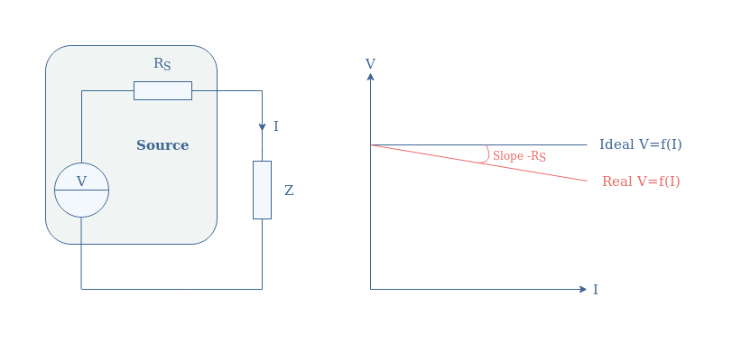
As stated previously, real voltage sources do not present a flat V/I characteristic. These power losses affecting the source are modelized by an internal resistance (or source resistance) noted RS and placed in series with the voltage source.
Figure 4 illustrates the circuit diagram of a real voltage source along with its voltage/current characteristic:
fig 4: Real voltage source supplying a load of impedance Z (left) and its associated voltage/current characteristic (right)
The value of RS is an important parameter to characterize voltage sources, it is also known as the voltage regulation.
Connection rules
Some connection rules are necessary to keep in mind when integrating voltage sources in a circuit.
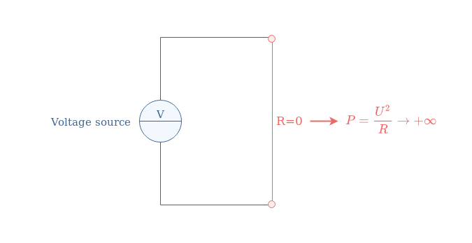
The first and most important one is to not place the voltage source in a short-circuit, we can also say to not short the source, such as illustrated in Figure 5.
fig 5: Voltage source shorted, forbidden connection
Shortening a voltage source is actually equivalent to imposing a potential difference V on a resistance equal to zero, which results in an active power tending to infinity. In practice, the internal resistance of the source and the connection wires will simply be submitted to a strong current resulting in their melting or irreversible damage to the source.
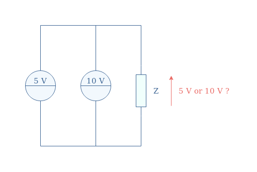
The second rule concerns parallel connections between 2 or more voltage sources. It is never recommended to connect voltage sources in parallel without any components in between, even when their value is strictly identical.
fig 6: Voltage sources in a parallel configuration, not recommended connection
The first reason why the circuit in Figure 6 is not realized is that a short circuit can be produced between the sources. In this example, a potential difference of 5V is generated between the wire connecting the sources, provoking a fast increase of the current since the equivalent resistance is zero.
Moreover, the output load Z will choose the source that can deliver the necessary power faster. Only the 10 V source will work, leaving the 5 V source being unproductive.
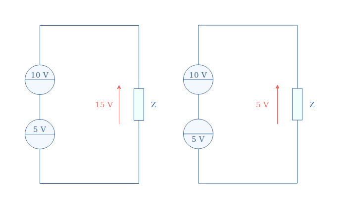
Finally, connecting voltage sources of equal or different values in series is allowed and frequently encountered to connect accumulators together (called a battery) in order to produce a higher voltage such as illustrated in Figure 7.
fig 7: Voltage sources in a series configuration, allowed connection
The resulting output voltage at the terminals of the battery of sources is the algebraic sum of the different sources used. When the sources are providing a voltage in the same direction (left circuit), the absolute values are in addition, when the directions are different (right circuit), the absolute values are subtracted.
Dependent sources
The values of the voltage sources presented in the previous sections are fixed and do not depend on any parameter or element of the surrounding circuit, they are therefore qualified as independentsources.
We present in this last section a different type of voltage source, known as dependent sources, which value is correlated to a parameter.
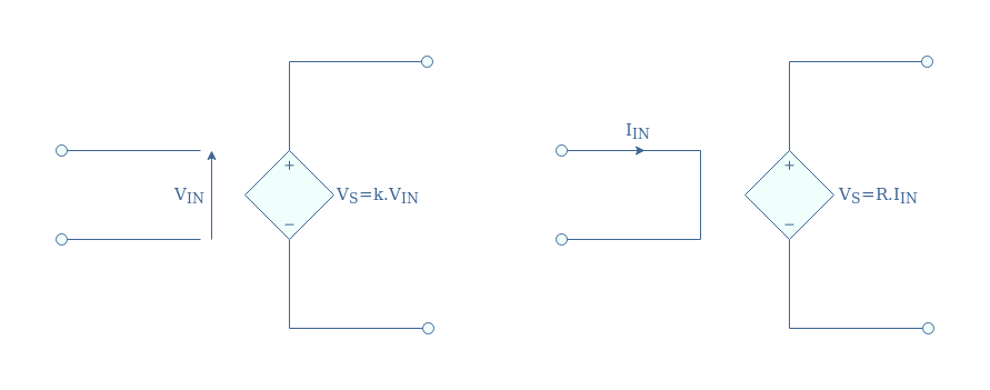
Dependent sources are quadripole components symbolized with a diamond shape in circuit diagrams:
fig 8: VCVS (left) and CCVS (right)
In the case of voltage sources, the control parameter can either be an input voltage (VIN) or a current (IIN). In the first case, we refer to it as a Voltage Controlled Voltage Source (VCVS), in the second case, we mention it as Current Controlled Voltage Source (CCVS).
Voltage Controlled Voltage Source (VCVS)
For VCVS, a dimensionless factor (k) called the gain links the input voltage and the output that the source generates.
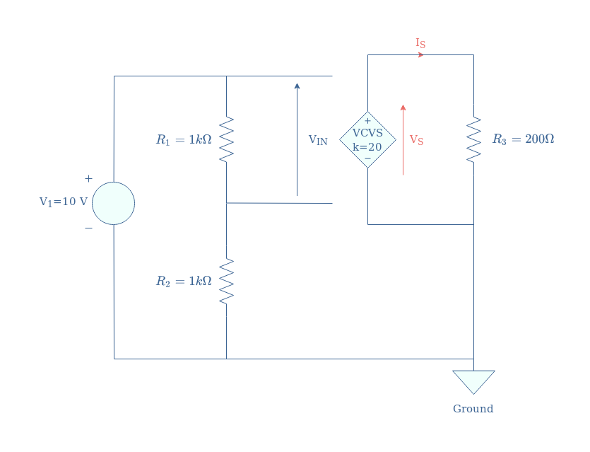
A VCVS is always controlled by a more or less complex circuit that provides an input voltage which will generate an output voltage to power an output load. A typical VCVS circuit is illustrated in Figure 9:
fig 9: A VCVS circuit
In this example, we want to show how to obtain the unknown output parameters VS and IS.
First of all, we can comment that the controlling stage consists of an ideal voltage source providing 10 V to a voltage divider circuit (R1 and R2). Since R1=R2, the output voltage of the voltage divider (or input of the dependent voltage source) is half of V1 and equal to VIN=5 V.
Since the gain of the VCVS is set to be 20, we can conclude that VS=20×VIN=100 V. The output current is simply computed with Ohm’s law: IS=VS/R3=0.5 A.
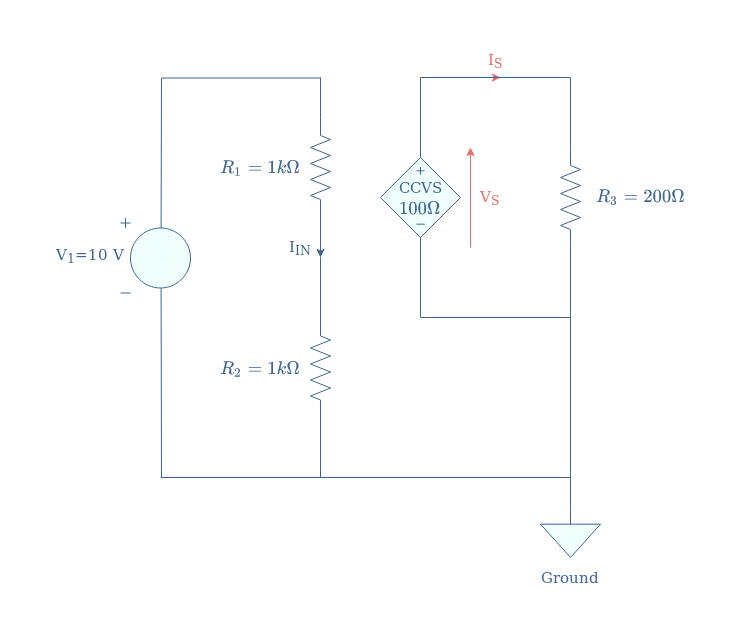
Current Controlled Voltage Source (CCVS)
For CCVS, the factor linking the input current to the output voltage is labeled R, which is not a coincidence since it is expressed in Ohm unit (Ω).
A typical CCVS can be designed similarly to the architecture presented in Figure 9 for the VCVS:
fig 10: A CCVS circuit
The input current IIN of the dependent voltage source is simply given by Ohm’s law: IIN=V1/(R1+R2)=5 mA.
The voltage delivered by the CCVS is found by multiplying this input current by the factor R: VS=R×IIN=0.5 V. We apply against Ohm’s law to find the output current IS=VS/R3=2.5 mA.
Conclusion
The most common devices that can be qualified for voltage sources are alternators and batteries. Alternators convert mechanical energy into an AC output thanks to the phenomenon of electromagnetic induction. On the other hand, batteries provide a DC output from a chemical source of energy.
Ideally, whether we deal with a DC or AC device, a voltage source should provide a stable and constant output value regardless of the output load, and therefore current that must be provided. Ideal voltage sources are defined by a flat voltage/current characteristic which implies that an infinite amount of power could be provided to a load.
However, voltage sources that can be found in real circuits are never ideal as they present an internal resistance (RS) that dissipates a fraction of the power they produce. This internal resistance is a modelization that reflects some dissipation phenomena, the component is not physically present in the design of the voltage source. Real voltage sources have a V/I characteristic defined by the function V=Videal-RS×I, when comparing it with the ideal characteristic, it presents a light slope of value -RS.
Some important connection rules are further given for voltage sources, shortening and associating voltage sources in parallel is not recommended since it can lead to a fast increase of the current which results often in burning wires or components. The series association of voltage sources is however allowed and commonly found to increase the total voltage output.
Finally, the last section of this tutorial presents the dependent voltage sources. The output of this type of source is controlled by an input that can be of two natures:
Voltage Controlled Voltage Sources (VCVS) are controlled by a voltage input
Current Controlled Voltage Sources (CCVS) are controlled by a current input
We present for each source a typical circuit and how to proceed to compute their outputs.
WIN Enterprises Announces Mini-ITX Form Factor with 8th Gen Intel® Core™ Processor for IoT and Factory Process Monitoring
WIN Enterprises, Inc., a leading designer and manufacturer of embedded x86 motherboards and appliances for electronic OEMs, announces the MB-50040. The MB-50040 is a high performance Mini-ITX single board computer (SBC) for graphically-oriented factory process monitoring and IoT applications that require high performance.
Multiple expansion: 1 PCIe x4, 1 M.2 M Key (SATA/PCIe), 1 M.2 E key (PCIe/USB)
Storage: 2 SATA 3.0
Rich I/O: 2 Intel GbE, 4 USB 3.1, 4 USB 2.0
15-Year CPU Life Cycle Support Until Q1′ 31
Three independent displays are supported for factory-line visualization. One display has DP++ resolution up to 4096 x 2160 @ 60Hz. To meet the requirements of a complete IoT architecture, the unit supports 2 SATA 3.0 for plenty of storage and communication to the Cloud. The 8th Generation processor provides a wide variety of performance-based on 2-, 4- or 8-core processing capabilities. Robust network and device connectivity is provided by 2x Intel GbE LAN, 4x USB 3.1, and 4x USB 2.0 along with multiple expansion capabilities.
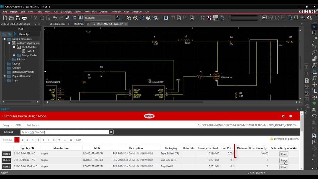
Simple, Frustration-Free Part Purchasing and BOM Creation.
Ultra Librarian is a free online resource to help take the busy work out of the design process by providing the largest amount of CAD models available for download.
Quickly find verified parts in our ever-expanding database of verified parts from the leading component manufacturers
Receive unlimited access to FREE schematic symbols, footprints, and 3D STEP models in your native CAD format
Get back to what matters most; innovation, not part creation
Features
Built to globally recognized industry standards from IPC – 7351B