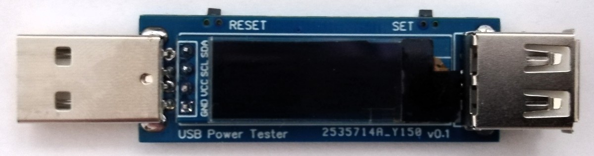
USB power testers provide users with the opportunity of examining how much power a device plugged into a USB port is drawing from the port. While this is mostly used by designers who are building USB-powered devices and are trying to evaluate how much power it consumes, it is sometimes also used to appraise the performance of the USB port to which the device is connected and the USB cable used for the connection, among other uses.
A typical approach, without a USB power tester, involves the use of a USB breakout board with a multimeter in between the device and the USB port. This is usually quite inconvenient and it’s the major reason why USB Power Testers are becoming more popular. While there are tons of brands diverse types of USB power testers in the market, Stefan Wagner thought it’d be cool to make a DIY version of the device, and he recently shared the beautifully designed device on his Github page.
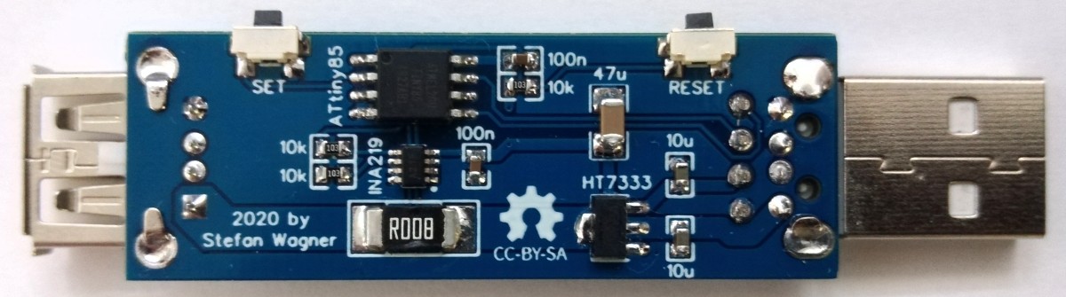
The project is based on the popular INA219 high-side current sensor, which is readily available on Platforms like Aliexpress etc. The project uses the ability of the sensor to measure both current and voltage being drawn by a connected load to monitor power consumption by a connected USB device.
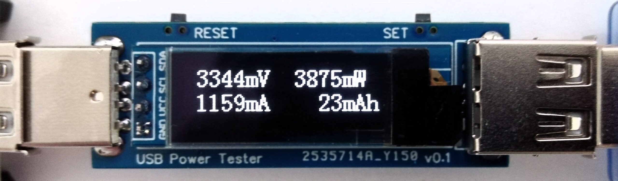
For processing the data from the sensor, the project uses the Attiny45/85 microcontrollers, leveraging on its small form-factor and low power features. Stefan is a big fan of the Attiny series of microcontrollers and has used them in several projects like the tinyRemotewhich we covered recently, among others. The data from the INA219 current sensor is displayed on a connected OLED display to provide user feedback and two small push buttons are attached on the sides of the device to allow users, switch between different screens.
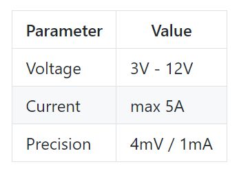
Some specifications and features of the device are provided below:
The project is totally open-source and all files like the schematics, PCB design files, and firmware, are all available on the project’s Github page.
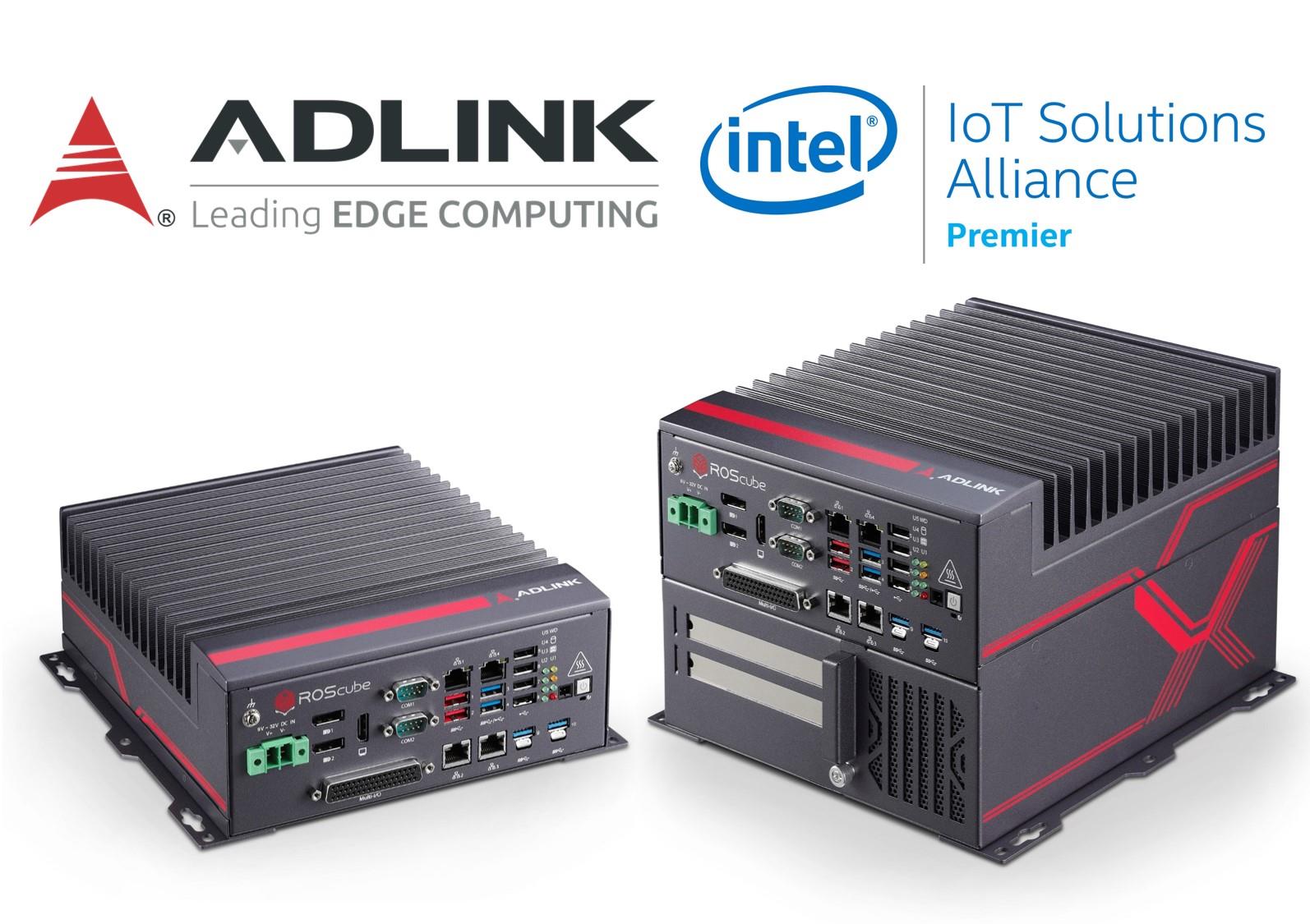
ROScube-I combines exceptional I/O connectivity and ROS 2 software platform for faster, easier, and scalable development of AI-based robotics applications.
ADLINK Technology, a global leader in edge computing, has launched the ROScube-I with Intel, providing a real-time ROS 2 robot controller for advanced robotic applications. The ADLINK ROScube-I Series is a ROS 2-enabled robotic controller based on Intel® Xeon® E, 9th Gen Intel® CoreTM i7/i3 and 8th Gen Intel® CoreTM i5 processors, and features exceptional I/O connectivity supporting a wide variety of sensors and actuators to meet the needs of a wide range of robotic applications. The ROScube-I supports an extension box for convenient functional and performance expansion with Intel® VPU cards and the Intel® Distribution of OpenVINOTM toolkit for computation of AI algorithms and inference.
Robotic systems based on the ROScube-I are supported by ADLINK’s Neuron SDK, our proprietary platform specifically designed for professional robotic applications such as autonomous mobile robots (AMR) and With the newly released ROS 2 Foxy Fitzroy (codename “foxy”), Neuron SDK customers can enjoy the benefits of long-term support (LTS), as well as ADLINK’s quality-guaranteed services for ROScube.
The ROScube-I series features:
High-performance x86-64 mainstream architecture for ROS 2 development
Comprehensive I/O for connecting a wide range of devices
Real-time I/O for environmental sensors (CAN, GPIO, COM)
Real-time middleware for communication between software components and devices
Hypervisor for safe mission critical mission execution
Ruggedized, secure connectivity with locking USB ports
Optional RTOS such as VxWorks
Developers can easily use the ROScube-I Starter Kit or ROScube Pico Development Kit (powered by Intel® CoreTM, Celeron® and Atom® processors) to rapidly prototype algorithms and immediately deploy them to ADLINK’s NeuronBot ROS 2-based rapid robotic development kit for demonstration. This allows for fast improvement of AI models and acquisition of vision data to optimize operational decision-making. The NeuronBot also supports ADLINK’s Neuron SDK to leverage the powerful open source ROS libraries and packages.
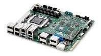
ROScube-I Starter Kit
The ROScube-I Starter Kit features:
Embedded board with rich I/O interface
MXM graphics module support for accelerated AI computing
Compatibility with ROS/ROS 2
OpenVINO™ support
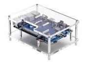
RSOcube Pico
The ROScube Pico Development Kit features:
Compatibility with Raspberry Pi 40-pin GPIO
Rich ROS open source applications
Compact size based on the SMARC form factor
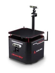
NeuronBot
The NeuronBot features:
Integrated vision, control, AI and motion modules
Rapid robotic development design
Support for powerful open source ROS libraries and packages
OpenVINO™ support
“With the rise of Industrial 4.0, robotics will become increasingly intelligent powered by edge computing and AI on the path to the autonomous factory,“ said René Torres, Vice President of the Sales, Marketing and Communications Group and General Manager of Industrial Solution Sales at Intel Corporation. “We are pleased to partner with ADLINK to enable the ROScube, a market leading innovative robot controller that is built to empower existing robotics solutions with high performance edge AI analytics for dynamic manufacturing environments. Powered with technologies such as Intel Architecture, Intel Iris Graphics, Movidius and OpenVINO the ROScube will enable new levels of performance and collaboration between multiple AMRs with real-time communication”
“ADLINK is working closely with Intel to apply artificial intelligence to edge computing and our new ROScube-I releases the potential for robotic companies to develop and deploy AI-based applications faster and easier than ever, so our industrial and commercial customers can optimize operational efficiency and expand business value,” said Dr. Ryan Chen, Director of the Advanced Robotic Platform Group at ADLINK. “We have also designed the ROScube-I Starter Kit and ROScube Pico Development Kit series as integrated hardware and software solutions which provide users with an ideal starting point to find AI value by enabling easy edge deployment of their models on our NeuronBot. This approach can then be scaled for industrial requirements using the same software platform but deployed on more powerful hardware as needed. This gives our customers the ultimate in future-proof flexibility by allowing them to immediately begin development with our comprehensive robotic solutions, and then make their hardware solution choice at deployment time.”
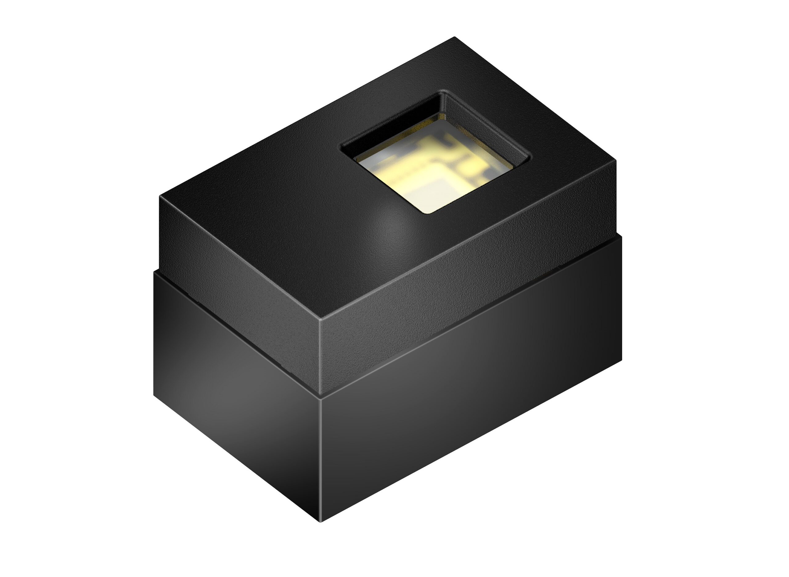
Osram’s first intelligent emitter module for 3D sensing allows smartphones to take high-quality images and videos with a staggered depth of field. In portrait shots, the person’s face remains in focus, while the background becomes blurred.
Besides optimizing image content, the module can also be used for 3D object recognition or augmented reality apps.
A central task for manufacturers of smartphones and tablets is to find the right emitters, photodiodes and VCSEL driver chips (ICs), then calibrate them and finally install them in the end device. With the VCSEL-based module Bidos PLPVDC 940_P_L01 specifically designed for Time-of-Flight-(ToF) applications, Osram now eliminates a large part of these tasks for manufacturers. The module features a black package, a 3-Watt infrared VCSEL with a wavelength of 940 nanometers (nm), a matching optical system, an integrated intelligent microcontroller for driving the VCSEL and a photodiode. Together, the individual components have a 3.6×5.46mm footprint. The unit’s high optical power enables the acquisition of depth information by ToF at a distance of up to seven meters. Special safety mechanisms are integrated in the module. If the photodiode registers a change in the incidence of light, if the optics are damaged after a fall, the current supply to the VCSEL is interrupted.
Portrait of smiling businesswoman outdoors in the city
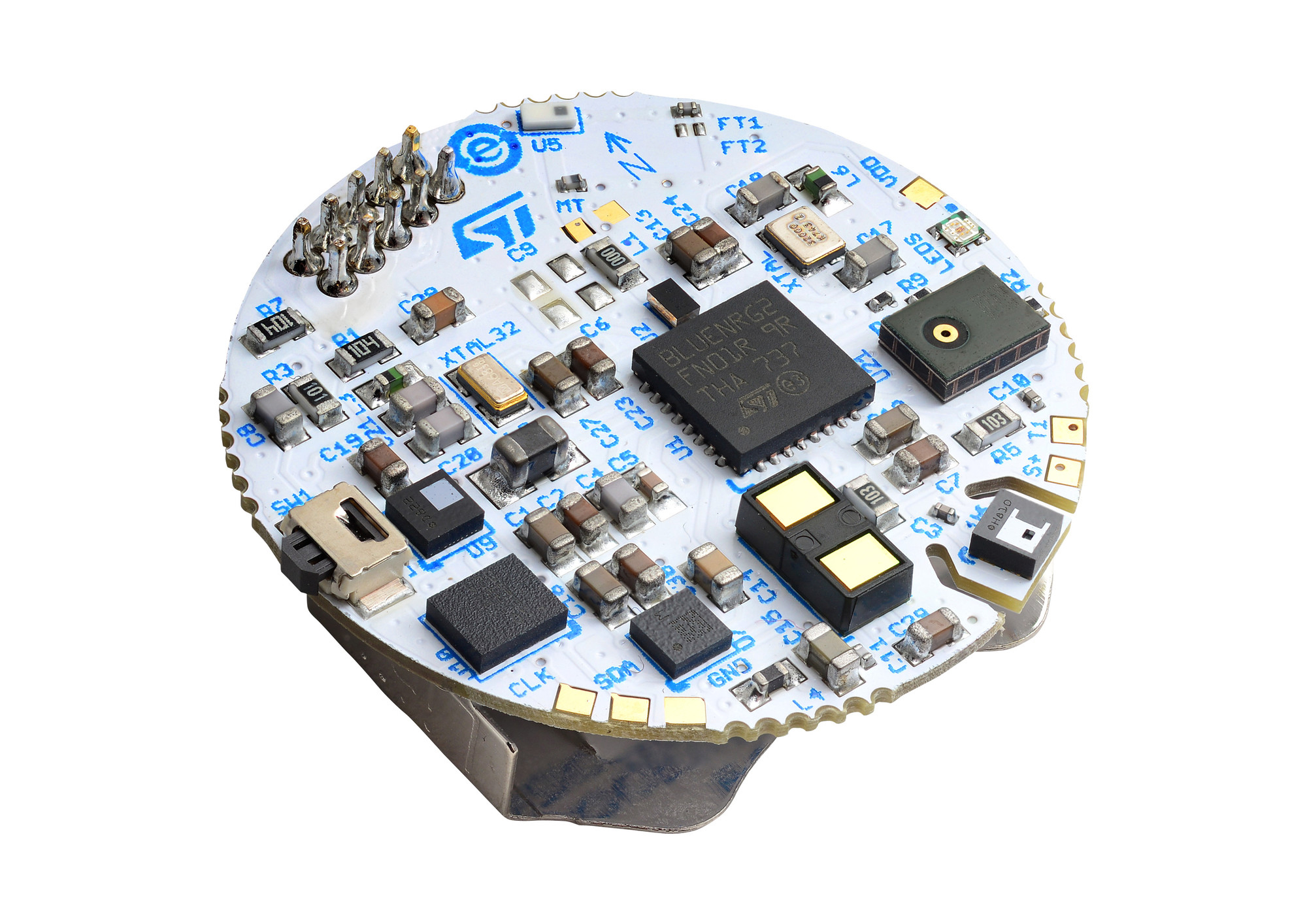
STMicroelectronics, a global semiconductor leader serving customers across the spectrum of electronics applications, announces the availability of a compact and cost-effective reference design ideally suited for monitoring social distancing, assuring remote operation, provisioning, as well as warning, anti-tampering, and potentially providing contact tracing to protect human health in all environments, including in response to global or local pandemic conditions.
Leveraging Bluetooth Low Energy technology through its incorporation of ST’s ultra-low-power BlueNRG-2 System-on-Chip with tunable RF output power, the BlueNRG-Tile reference design measures the signal strength of nearby Bluetooth non-connecting beacons and, in real-time, calculates proximity to these sources. The circuit can be provisioned and then operate, issuing warnings when another beacon intrudes on an adjustable perimeter or when tampered with – even when not connected to a smartphone or 5G network. The base reference design can be supplemented with ST’s S2-LP sub-GHz ultra-low-power RF transceiver to add bi-directional tag-to-cloud communication through the Sigfox “0G” Global Network, allowing private and anonymous tag provisioning, notifications, and an advisory return-channel for emergency warnings. To assure power economy and extend battery lifetime, the ultra-low power components are further enhanced with a MEMS (Micro-Electro-Mechanical Systems) accelerometer that power cycles the unit when it isn’t moving. Optionally, internal or external memory could provide long-term storage of nearby beacons, allowing contact tracing.
“Developing this highly-efficient and cost-effective social distancing reference design has significant value in any environment where people need to work safely,” said Benedetto Vigna, President Analog, MEMS and Sensors Group, STMicroelectronics. “This compact design can be used as is or enhanced for a wide range of applications, including as bracelets and bands or as plugins or add-ons to eyeglasses, helmets, and masks and shields.”
Several members of the ST Partner Program have evaluated and adopted the reference design as a foundation for location-monitoring and contact-tracing platforms. These platforms provide a range of capabilities, including proximity alerts and contact recording, using the ST reference design packaged in compact, ultra-low-power tags.
The Social Distancing reference design, including further technical detail on its operation, is available on ST.com and through local ST sales offices.
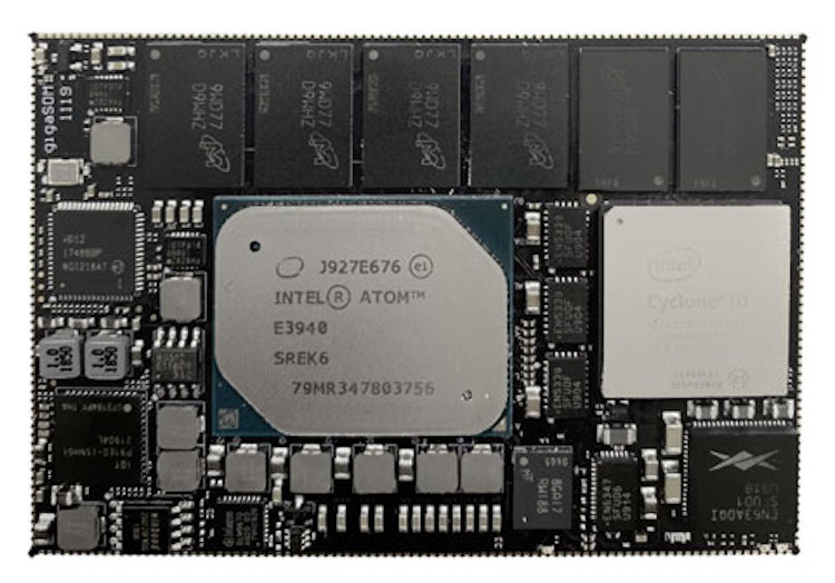
Arrow Electronics has collaborated with Exor Embedded to create gigaSOM gS01, a full production design and an additional development kit featuring a high-performance, energy-efficient system on module (SOM) for IoT edge deployments. [via]
The SOM combines the power and efficiency of the Intel Atom E3900 processor series with the flexibility of an Intel Cyclone 10 GX FPGA, connected with a high-bandwidth dual-lane PCIe interface to create a unified high-performing engine.
gigaSOM gS01 is a combined X86 CPU and Intel high-speed FPGA design on a single system on module.
With Intel’s time-coordinated computing (TCC) technology in the CPU, support for IEEE 802.1 time-sensitive networking (TSN) in the FPGA reference design, and loaded with a real-time IoT stack, the gigaSOM gS01 ensures determinism for managing synchronized and real-time smart-factory applications.
The board can consolidate multiple devices such as industrial PCs, HMI controllers, and PLCs in a single module.
Support for MQTT (MQ Telemetry Transport) and OPC UA (Open Platform Communications Unified Architecture) lightweight protocols lets users connect easily with Corvina Cloud – Exor’s sensor-to-cloud platform – for collecting machine IoT data and orchestrating industrial assets.
Corvina Cloud provides resources such as machine model instances on a software-as-a-service (SaaS) basis and has features to help users derive visual trends and analytic apps leveraging collected data.
With the Intel Atom E3900 CPU series, the board delivers high performance per Watt. In addition, Intel SpeedStep technology dynamically adjusts the operating voltage and frequency to optimise efficiency at any CPU loading.
Users can take advantage of extensive graphics features including Intel HD Graphics 500, DirectX and OpenGL support, and Intel Clear Video HD Technology, and DisplayPort, eDP, HDMI, and MIPI-DSI outputs to connect up to three displays.
The board provides multiple high-speed interfaces including two USB2.0, two USB3.0, and two SATA3 ports, Gigabit Ethernet, PCIe, six 10Gb FPGA transceivers, and 34 LVDS pairs. There are also SMBus, multiple I2C, CAN, and SPI connections. Both the microprocessor and FPGA feature plentiful GPIOs.
The gS01 SOM is available with four configurations, giving developers a choice of E3930 processor with or without an 85,000 logic-element Cyclone 10 GX FPGA or E3940 processor with or without 220,000 logic-element Cyclone 10 GX. Memory options include 4GB or 8GB DDR RAM, 32GB or 64GB flash disk, and 64KB FRAM.
The module has a low profile of just 4.9mm and measures 81.6mm x 54mm, allowing creation of slim and compact products.
The FPGA and CPU are soldered directly to the board to maximise reliability and ruggedness, making the module an excellent choice for 24/7 operation and deployment in hostile environmental conditions across the temperature range -40°C to 85°C.
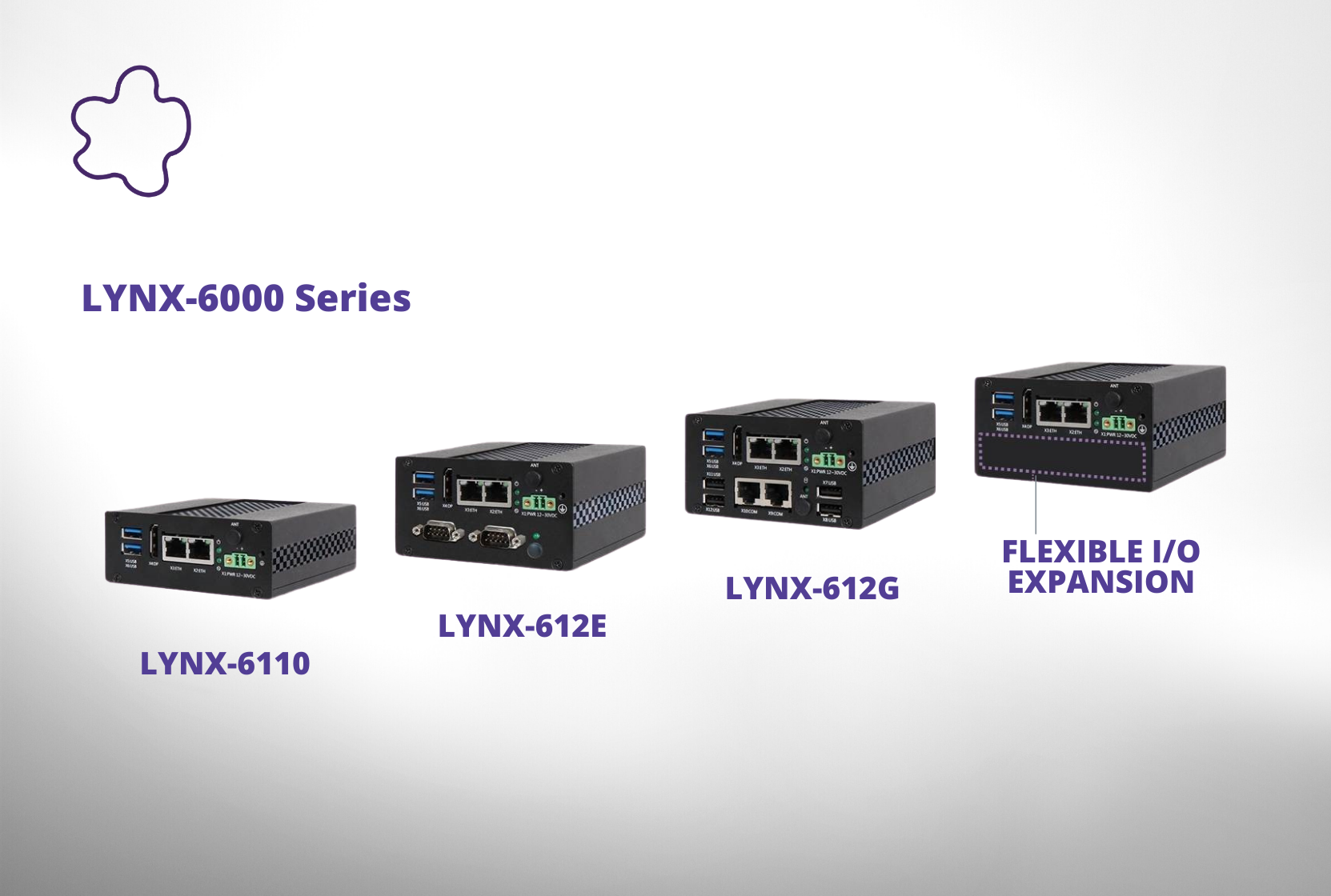
American Portwell Technology, Inc., (https://www.portwell.com), a world-leading innovator in Industrial PC (IPC) and Associate member of the Intel® Internet of Things (IoT) Solutions Alliance, announces the LYNX-6000 Series, a new generation of palm-sized, ready-to-use industrial IoT gateway solutions based on Intel Celeron® N3350 CPU (formerly Apollo Lake platform) and also certified by Microsoft® Azure® IoT that provides a scalable infrastructure for data, virtual machines, server and front-end applications. According to Jack Lam, senior product marketing director at American Portwell Technology, the new LYNX-6000 Series provides a rich portfolio of ultra-small form factor IoT appliances that offer a variety of features including low power consumption connectivity and expansion, ruggedized design, and industrial regulatory compliance.
LYNX-6000 Series with Highly Flexible I/O and Expandable Capabilities
Through modular design, LYNX-6000 Series features an impressive combination of modern and legacy I/O connectivity, plus an additional proprietary expansion slot allows LYNX-6000 Series to enhance I/O connectivity and increase system functionality via various add-on I/O options.
LYNX-6110: The Basic Model Suitable for Edge Computing
Features of the LYNX-6110 basic model include Intel Celeron N3350 processor (Apollo Lake platform); onboard 4GB LPDDR4 DRAM (up to 8GB); onboard 32GB eMMC 5.0 (up to 256GB); operation at <10W for energy efficiency; 2x GbE LAN, 2x USB 3.0, 1x DP with resolution up to 4K; 1x M.2 Key E 2230 for wireless module; wide power input ranges from 12-30 VDC; ruggedized, fan-less and advanced thermal design; DIN-rail and wall mount options; certified with heavy industry EMC and EMI class B; and optional wide operating temperature support and customized appearance service.
LYNX -612E: Suitable for IoT Gateway in Industrial Automation Environments
LYNX-612E with enriched legacy industrial control interfaces is designed as a software-defined gateway for a variety of industrial automation environments. In addition to common features, it includes 1x Full-size Mini-PCIe, 1x M.2 key B 2242 for expansion (such as storage, Wi-Fi or Bluetooth®), 1x RS-232 and 1x RS-232/422/485 (BIOS configurable).
LYNX -612G: Suitable for IoT Gateway with Enriched I/Os for Expansion
LYNX-612G is designed for the compact IoT gateway that requires enriched I/O ports for expansion or connectivity. In addition to the common features, it includes 1x Mini-PCIe and 1x M.2 key B 2242 for expansion (such as storage, Wi-Fi, Bluetooth®, LoRa or LTE modules), 2x RS-232 and 4x USB 2.0.
Wide Range Applicability
With modularized I/O options, LYNX-6000 Series can easily function with a variety of different applications. The compact system is equipped with rich interfaces for data acquisition and server connection. Various communication ports help connectivity for machines-to-machines; wireless function is also available for remote controllability and manageability.
Portwell’s LYNX-6000 Series is an ideal IoT solution for industrial/factory automation, facility management, transportation, intralogistics or smart warehouse, medical equipment, communication testing equipment, electrical charging station management, automated guided vehicle (AGV) and IoT nodes for data collection/ management, and edge computing.
Palm-Size Power and Innovation for Integrated IIoT Solutions
“Portwell’s LYNX-6000 series offers the industrial IoT market a rich portfolio of ultra-small form factor devices with state-of-the-art expansion design to ensure that various I/O choices for different applications are fulfilled with minimal investment,” states Lam. “Whether you need to perform data collection and transition, edge computing or communication tasks in applications like industrial automation, intralogistics or smart retailers, Portwell’s LYNX-6000 series can more than handle the task. Designed with the latest Intel Celeron N3350 at a mere 100 x 53.5 x 92 mm, its ultra-small palm-size form factor can easily fit into limited spaces. Plus,” Lam adds, “its ruggedized design makes it ideal for the harsh industrial environment. This flexible, fan-less and ready-to-use industrial IoT appliance from the leading IoT solution provider is the perfect choice for people looking to reach their goal of quick time-to-market for their product or time-to-complete for their project.
“And as always,” Lam confirms, “our customers not only benefit from the most up-to-date technology and features, but they also gain peace of mind from the long lifespan support (7+ years) inherent with every Portwell product.”
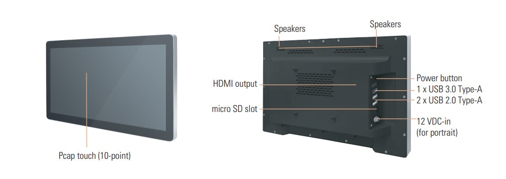
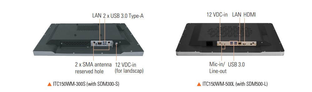
Axiomtek – a world-renowned leader relentlessly devoted in the research, development and manufacture of series of innovative and reliable industrial computer products of high efficiency – is pleased to launch the ITC150WM-300S and ITC150WM-500L, two 15.6-inch modular panel PCs with a swappable signage computer module which is based on the newest Intel® Smart Display Module (Intel® SDM) architecture. The swappable design makes the system maintenance easier in field replacement and upgrade. The ITC150WM-300S and ITC150WM-500L have a 15.6-inch full HD LCD display with 1920 x 1080 resolution, a 10-point projected capacity touchscreen, 300 nits of high brightness and LED backlights. The thickness of both interactive panel PCs is less than 40 mm, which is suitable for use in a space-constrained environment.
“The ITC150WM-300S and ITC150WM-500L support Axiomtek’s SDM-based signage computer modules: SDM300S (Intel® SDM-S) and SDM500L (Intel® SDM-L), respectively. These two SDM-based modular panel PCs are designed for simplifying installation, upgrade and maintenance. Their unique modular design brings great convenience for users and greatly reduces maintenance costs,” said Leo Chen, a product manager of Product PM Division at Axiomtek. “The ITC150WM-300S and ITC150WM-500L have a metal frame structure and IP54-rated front bezel to protect from dust ingress and water spray. These interactive panel PCs bring possibilities to the retailers.”
The ITC150WM-300S is powered by the onboard Intel® Pentium® processor N4200 and Celeron® processor N3350 with the Intel® HD Graphics 505 or 500 chipset. This SDM-S based panel PC can operate quietly and reliably in rigorous environments. It features one 4GB or 8G LPDDR4 memory onboard, plus an onboard 64GB eMMC. The ITC150WM-300S supports rich I/O interfaces, including three USB 3.0 Type A, two USB 2.0 type A, one HDMI, one GbE LAN, one push-push type micro SD card slot, and two SMA-type antenna openings. The ITC150WM-500L is powered by the Intel® Celeron® 4305UE with the Intel® UHD Graphics 610 chipset. This SDM-L based panel PC has two 260-pin DDR4-2400 SO-DIMM slots with up to 64GB of memory capacity and one M.2 Key M2280 slot for extensive storage. This all-in-one touch panel PC comes with five USB 3.0 Type A, two USB 2.0 type A, one GbE LAN, one HDMI, one audio, one micro microphone input, and one push-push type micro SD card slot.
Supports add-on modules and mounting kits (optional)
The ITC150WM-300S and ITC150WM-500L have two 1.5-watt stereo speakers with a sound pressure level of 96dB and 4 Ohms impedance. Both panel PCs also have one M.2 Key E 2230 slot for Wi-Fi. Moreover, these reliable panel PCs support add-on modules and flexible mounting kits to meet user requirements and easy deployment. They also have a +12V DC power supply input. The ITC150WM-300S and ITC150WM-500L are now available for purchase. For more product information or customization services, please visit our global website at www.axiomtek.com or contact one of our sales representatives at info@axiomtek.com.tw.
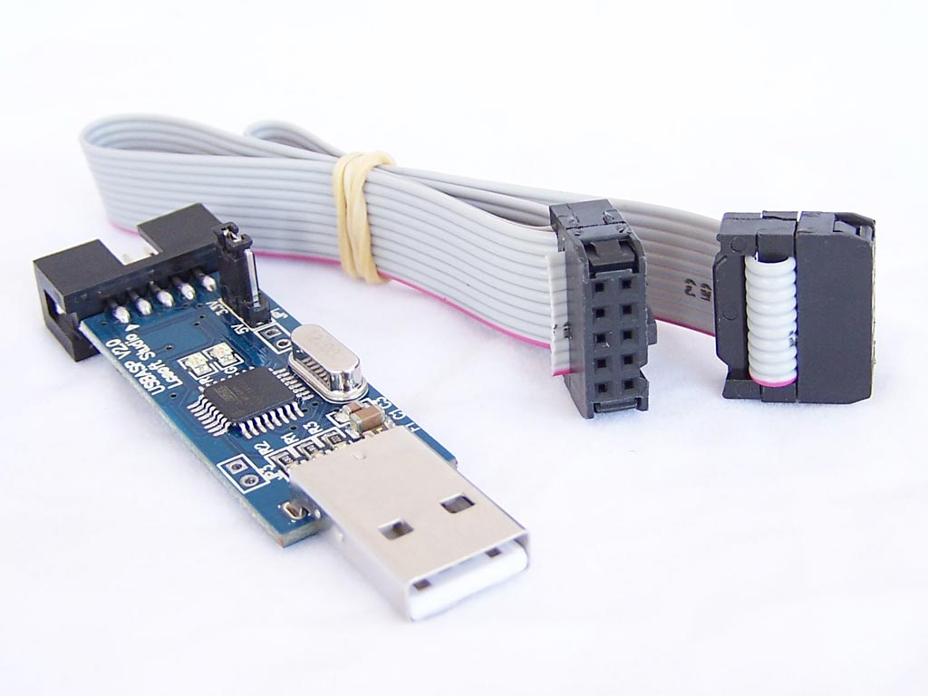
The USBASP programmer is an important tool/accessory for embedded systems engineers/ firmware developers. It is a USB ICSP (In-Circuit Serial Programmer) that allows developers to easily upload firmware/bootloaders on AVR microcontrollers. Unlike what you find to serial programmers like the USB-TTL converters, it does not use a dedicated chip as it runs on an atmega88 (or atmega8), and uses a firmware-only USB driver with no special USB controller required.
USBASP Programmer
While this firmware-only USB driver approach increases its compatibility, it also introduces a major challenge to the programmer as it requires regular updates for compatibility with advancements in how microcontrollers are programmed. One such advancement is the Tiny Programming Interface (TPI) that allows external programmers to access the nonvolatile memory (NVM) of certain low-end Atmel microcontrollers like the ATtiny series.
While features like TPI has been around for a while, using a USBASP programmer is still a problem as both old and new USBASP devices require a firmware update before they can be used. To help users who need this feature, today’s tutorial will spotlight the process involved in updating the firmware on your USBASP programmer to the latest version.
Required Components
The following components are required to perform the firmware update:
The USBASP Programmer
An Arduino Uno (a nano should equally work)
Jumper wires
Breadboard
USBASP programmers, irrespective of brand, typically have the same configuration, so this tutorial should work, irrespective of the type or brand that you have.
Prepare the Arduino Uno
Uploading firmware to the USBASP requires a programmer. For today’s tutorial, we will use an Arduino Uno as that programmer. To make the Arduino a programmer, we need to upload a sketch, available among the examples on the Arduino IDE, to the Arduino board. Follow the steps below to do this:
Go to File > Examples > ArduinoISP
Connect an Arduino board to your PC
Select the port and board type and Click on Upload
With this done, the Arduino board is now ready to serve as a programmer.
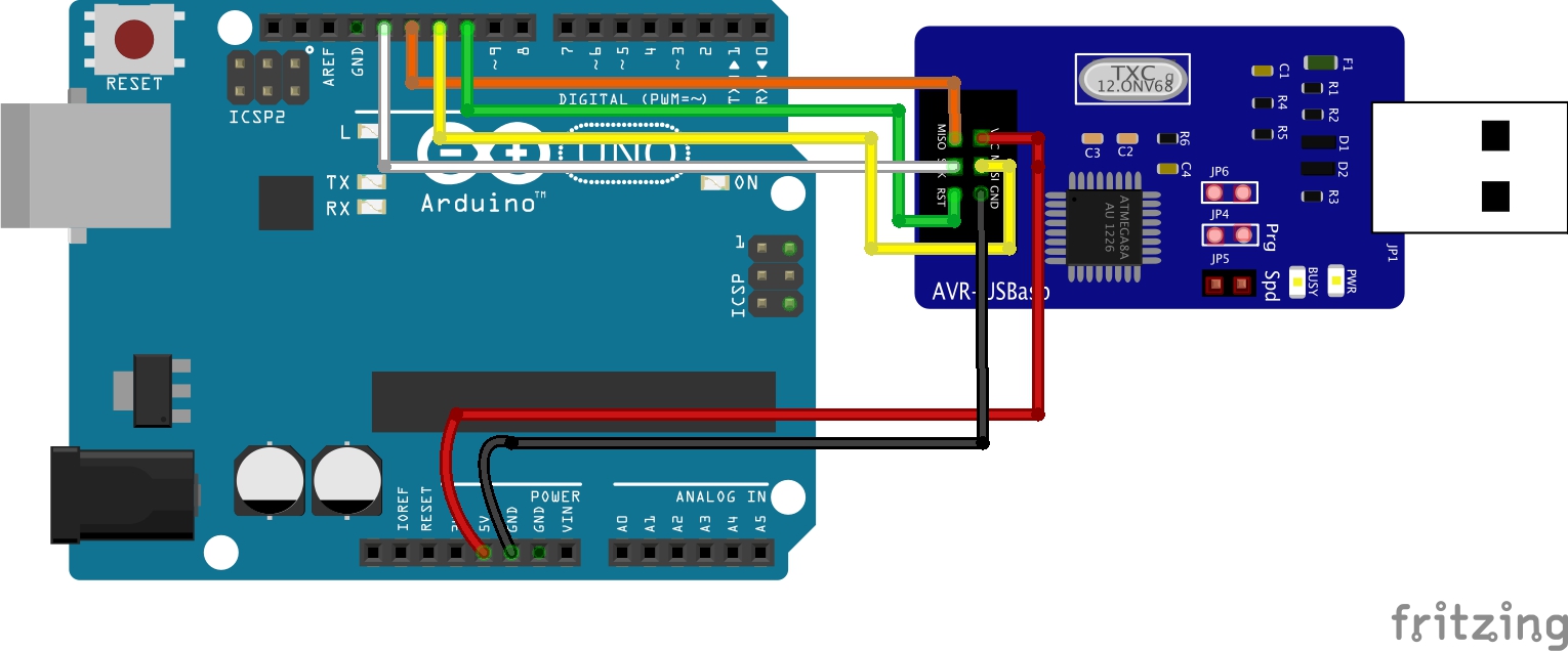
Schematics
Next, we need to connect the USBASP to the Arduino Board. Using jumper wires and the breadboard (if necessary) connect the Arduino board and the USBASP device as shown in the image below:
Schematics
Since the fritzing model is not an exact replica of the popular USBASP types, a pin map showing how the Arduino is connected to the USBASP is provided below to make the connection easier to follow:
Go over the connections once again to ensure it’s properly done. If you have doubts about identifying the pins on your USBASP, you can run a google search for the pin-out of that particular board and use it as a guide for the connection.
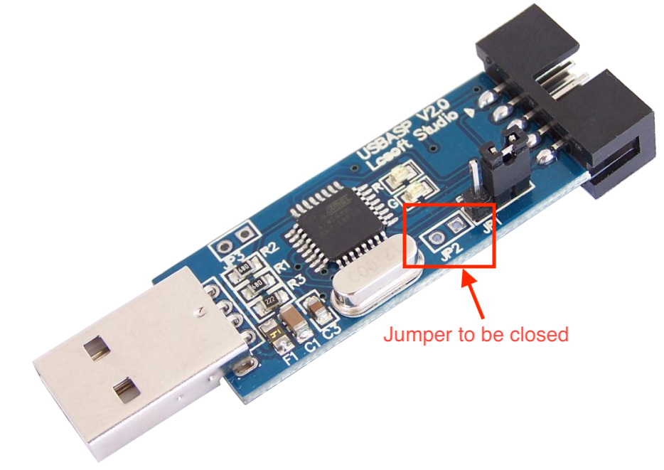
With the boards connected, one more thing we need to do is to close the Jumper JP2 (highlighted below) on the USBASP board. Without doing this, we will not be able to upload firmware to the device. Close the jumper by bridging it with solder led or jumper wires.
With this done we are now ready to upload the firmware.
Uploading the Firmware
We start by downloading the firmware. A repository containing the latest version of the firmware is maintained on Thomas Fischl’s website. As at the time of this writing, the latest version which thankfully has TPI support was released in May 2011. Download that.
A key ingredient of the firmware upgrade process is the AVRDUDE. If you are familiar with the Arduino IDE, you would definitely have seen a reference to it in the verbose during code upload. The AVRDUDE is an utility to download, upload, and manipulate the ROM and EEPROM contents of AVR microcontrollers using the in-system programming technique (ISP). The easiest way to get the AVRDUDE is by fetching its executable located within your Arduino folder -> “ARDUINO FOLDER”/Java/hardware/tools/avr/bin/ or you can downloading it.
Once you have it, the next step is to find it’s configuration file; avrdude.conf file, which (if you follow the Arduino IDE route) would be at the directory -> “ARDUINO FOLDER”/Java/hardware/tools/avr/etc/
Put these two files (the AVRdude executable and configuration file) inside a folder along with the .hex file of the USBasp firmware we just downloaded. This helps shorten the length of the final command. With these done, connect the Arduino with the USBasp programmer attached to it, to your computer, and note down the port that was assigned to the Arduino by your computer.
Finally, open a terminal window, navigate inside the folder we created earlier, and run the command below:
Ensure you enter the right port after the option -P. If this succeeds without any error message, then your USBASP now has the latest firmware, and it’s ready for some action.
That’s it for this tutorial!
Do feel free to reach out to me via the comment section if you have any challenges with getting this to work.
Measuring voltage and current is an important part of the development process for any hardware product. Especially when developing a low power device, the knowledge of how much power the device is drawing at each mode of its operation is critical to the correct estimation of its battery life.
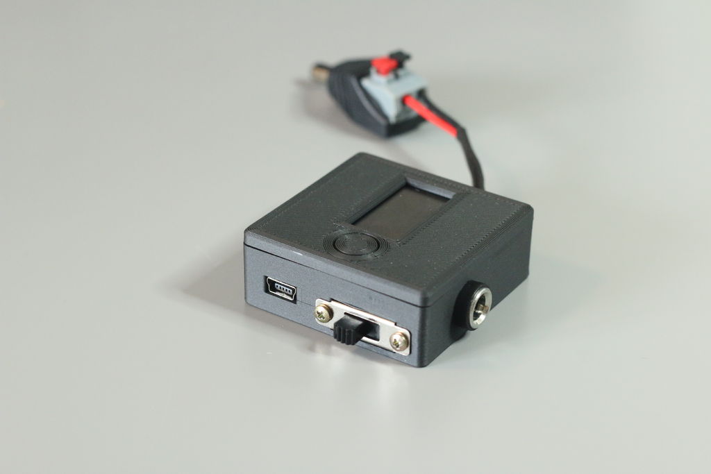
While voltage can be measured in a straightforward manner, current usually require a more strenuous approach with a shunt, which if not properly selecterd could lead to errors. Even when these two are properly calibrated in the form of a meter, the tethering wires between the device and the meters can make the process not so interesting, especially when you have to do it repeatedly. To solve this, Karl Torp decided to build a palm-sized, one-for-all meter called; the Tiny V/A.
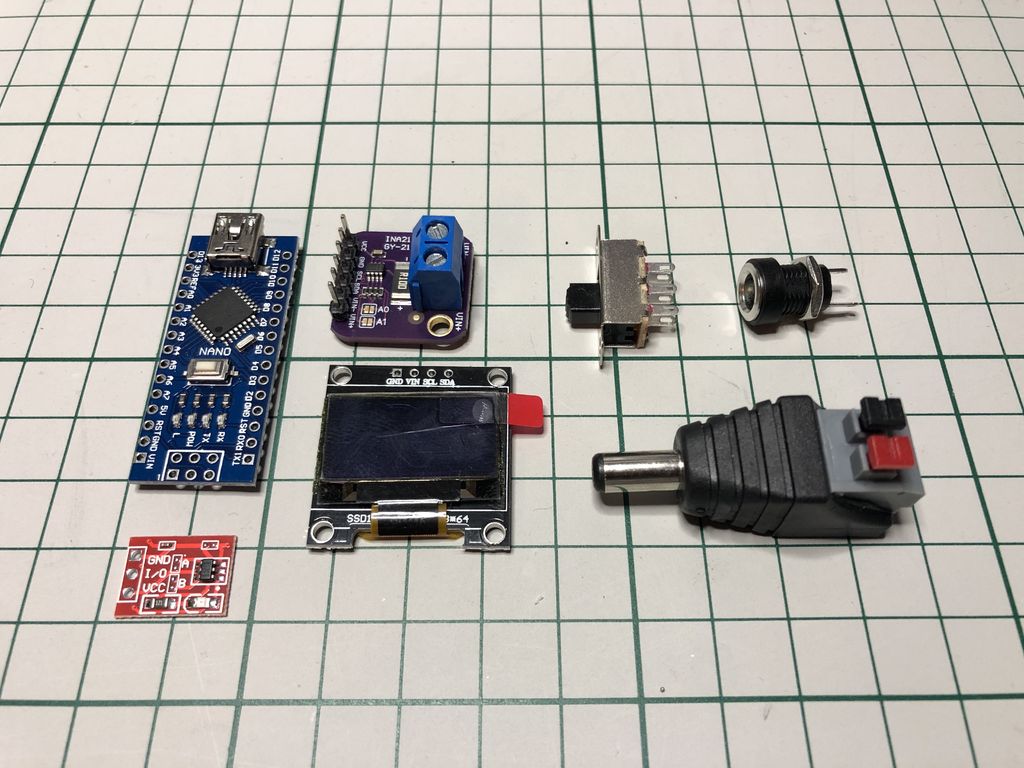
Based on the Arduino Nano, the TinyV/A comprises of the nano, an INA219 sensor, a 0.96” OLED display, and a single capacitive touch button, all neatly housed inside a 3D-printed printed enclosure. It operates in a manner similar man-in-the-middle technique, taken in input from a power supply via a female barrel jack connector and supplying power to the load through a male connector output.
The INA219 is a popular high side current sensor, readily available on Platforms like Alibaba, and its ability to measure both current and voltage on a load is the rock upon which the project is built.
Another interesting element featured in the project is the single capacitive touch buttons which are meant to allow users to easily navigate the Tiny V/A’s menu and change certain settings like the sensor range and refresh rate.
Some features of the tinyV/A meter include:
It can be powered from USB or from the power input.
When supplied from USB the input supply can range from 0 – 26V. Only leak current of sensor affects the power input. Nice if you want to verify the capacity of a battery.
When supplied from power input this can range from 4 – 15V. (Limitations of arduino voltage regulator).
Selected input is detected on boot or change and will display a range message to the user.
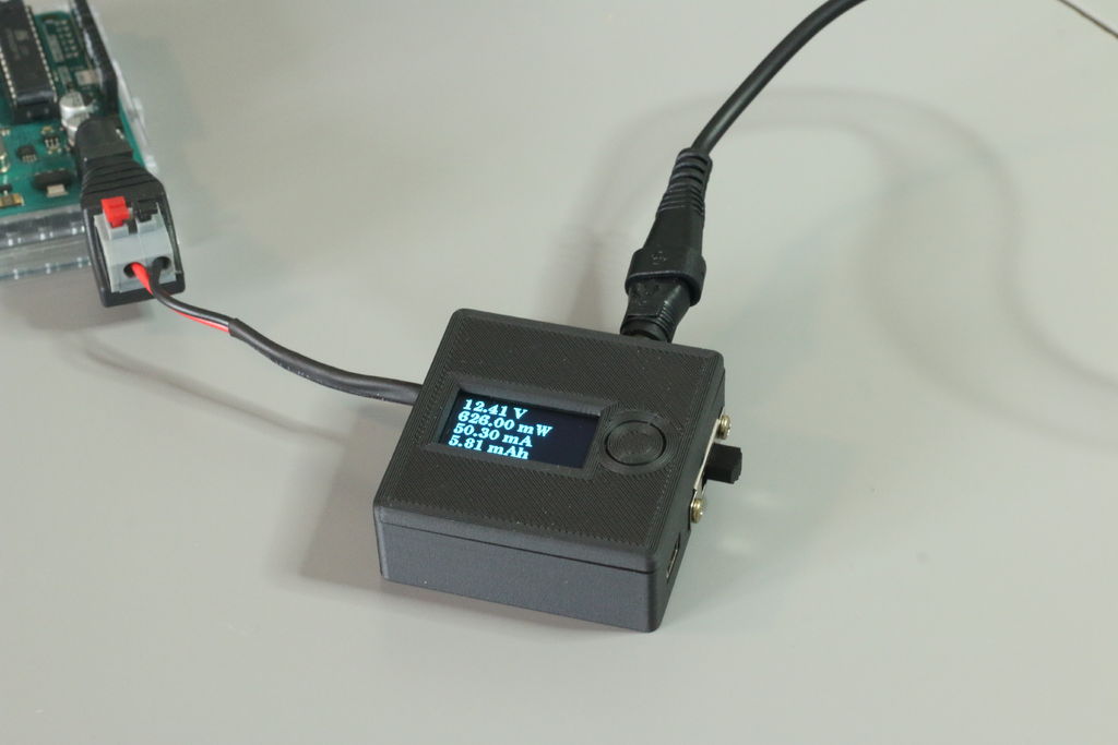
Can display voltage, current, power & mAh simultaneously.
Enable/disable sensor sleep to lower leak current in the sensor.
Settings are stored in EEPROM and reloaded on boot
Serial interface
Prints results on serial. It can be used for logging.
Change settings with serial commands
The project is entirely open-source and all the design elements including schematics, BOM, firmware, build guide, etc., that you may need to replicate it, is available on the project’s project’s page.
Infineon Technologies AG releases the BCR431U. The constant current linear LED driver IC provides low-voltage drop performance for regulating LED current. It is the second device released in the new generation BCR family with low voltage drop focusing on low current designs of up to 37 mA. Typical applications for the new BCR431U include LED strips, channel letters, architectural LED lighting, LED displays, as well as emergency, retail, and appliance lighting.
The voltage drop at the integrated driver IC can go down to 105 mV at 15 mA. This is unmatched in the industry and provides far more flexibility in lighting applications. It improves the overall efficiency and provides the voltage headroom required to compensate for the LED forward voltage tolerances and variances in the supply voltage. The BRCU431U allows either to add additional LEDs to lighting designs, for example, seven instead of six LEDs in series driven by one IC. Or it can be used to increase the overall length of a LED strip design from, for example, 5 to 7 m. Overall, longer LED strips mean fewer feeding points and less efforts in installation.
The LED current is easily adjustable via a high ohmic resistor on a dedicated pin with an IC supply voltage ranging between 6 V and 42 V. For safe and reliable operation and to extend the overall LED system’s lifetime, a smart over-temperature controlling circuit keeps the current constant even at rising temperature. At the same time, it reduces the LED current only when the junction temperature gets very high. The BCR431U features a dimming capability of down to 1 percent, which makes it attractive for a great variety of LED strip designs.
Availability
The BCR431U can be ordered now in a SOT-23-6 package. In addition, a demo board is available. More information is available at www.infineon.com/bcr431u.