STSPIN32F025x and STSPIN32F060x system-in-package are an extremely integrated solution for driving three-phase applications
STSPIN32F025x and STSPIN32F060x system-in-package are an extremely integrated solution for driving three-phase applications.
It embeds an STM32F031 featuring an ARM® 32-bit Cortex®-M0 CPU, has extended temperature range -40 °C – 125 °C, and a 250 V or 600 V triple half-bridge gate driver, able to drive N-channel power MOSFETs or IGBTs.
A comparator featuring advanced smartSD function, high-voltage bootstrap diodes, multi-channel 12-bit ADC, anti-cross-conduction, deadtime, and UVLO protection are also included.
Key features
Embeds STM32F0 MCU and 250 V / 600 V 3-phase BLDC Driver
Fully compatible with STM32 ecosystem
Extended temperature range: -40 to +125 °C
Smart shutdown (smartSD) and protection functions
Additional features
Three-phase gate drivers
High voltage rail up to 250 V
Driver current capability:STSPIN32F0251: 200/350 mA source/sink currentSTSPIN32F0252:1/0.85 A source/sink current
Driver current capability:STSPIN32F0601: 200/350 mA source/sink currentSTSPIN32F0602:1/0.85 A source/sink current
dV/dt transient immunity ±50 V/ns
Gate driving voltage range from 9V to 20V
32-bit ARM® Cortex®-M0 core:
Up to 48 MHz clock frequency
4-Kbyte SRAM with HW parity
32-Kbyte Flash memory with option bytes used for write/readout protection
“Pandemic,” it’s a scary word to hear. Especially when it’s accompanied by panic-buying of canned goods, pasta, and the disappearance of most disinfecting products from stores. As soon as various media outlets started filling up their news cycles with stories about the coronavirus, alcohol, hand sanitizer, and other disinfectants flew off the shelves. Panic-buying left the most vulnerable without essential goods needed to protect themselves, with little recourse available. Facing such a bleak scenario, one such person turned to their son, Md, a BotFactory applications engineer for help.
“Hey son, when you’re done removing the viruses from my computer, can you remove the viruses from my phone too?” Asked Md’s father. “Sure dad, gimme a few minutes, this will take a little time since we don’t have any disinfectant left,” responded Md. Both of them looked at each other quizzically. Then Md was struck with a brilliant idea; a bright idea, if you will. Ultraviolet light, in particular UVC light, is a shortwave ultraviolet light which can kill germs. Md thought to himself, “This would be a great way to clean items without any disinfectants.” The added benefit to using UV light instead of the highly sought-after cleaners, was that there was no need to go to the store or to lessen the availability of such products for others. Md was approached with a problem and delivered a very efficient and socially responsible (thinking of you Grandma!) solution.
Arrow Electronics, Inc. and Shiratech have announced the launch of IoT Box, a multi-purpose IoT edge node and gateway solution that enables sensors and actuators to be connected directly to the cloud.
IoT Box was developed by Arrow and Shiratech in conjunction with STMicroelectronics (ST). Potential uses for the product include air quality monitoring, safe city/smart city, voice-sensing, home appliance, smart edge node, and industrial gateway applications.
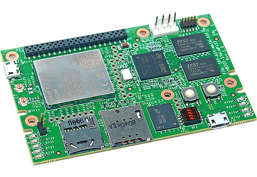
At the heart of IoT Box is Stinger96, a single board gateway based on the 96Boards IoT Edition specification, which is coupled with a proprietary mezzanine board to provide multiple wireless connectivity and sensor options. IoT Box is battery-powered, simplifying deployment in areas where mains power may be inaccessible or costly to access, and runs Linux Yocto.
Stinger96 is designed around ST’s STM32MP157 microprocessor based on dual Arm® Cortex®-A7 cores and an Arm Cortex-M4 core. The board supports LTE Cat-M1, NB-IoT and EGPRS wireless connectivity with maximum data rates of up to 375/300 kbps uplink and downlink, respectively. It features global frequency bands, GPS and ultra-low-power consumption. Hardware connectivity includes micro USB, micro SD and micro SIM. The Stinger96 board is available separately for users who wish to develop their own gateways.
IoT Box builds on Stinger96’s capabilities adding WLAN 802.11b/g/n connectivity up to 65Mbps and Bluetooth v4.2+EDR. It features an ultra-low-power digital gas sensor for monitoring indoor air quality and two high-performance digital MEMS microphones. IoT Box also has a selection of GPIO and sensor interfaces including I2C, SPI and UART, and a rechargeable Li-ion 2000mAH battery.
IoT Box is part of Shiratech’s and Arrow’s iCOMOX industrial IoT platform solution family.
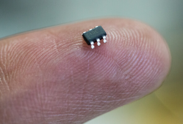
The ATtiny10 is a high-performance, low-power Microchip 8-bit AVR RISC-based microcontroller which combines 1KB ISP flash memory, 32B SRAM, 4x general-purpose I/O lines, 16 general purpose working registers, a 16-bit timer/counter with two PWM channels, internal and external interrupts, programmable watchdog timer with internal oscillator, an internal calibrated oscillator, a 4-channel/8-bit A/D converter, and four software selectable power saving modes, all these into a tiny 6 pin SOT23 package. For DIY enthusiasts and product designers who are looking to build products with low power consumption and a form factor, the ATtiny10 is definitely one of the microcontrollers that should be considered as it supports voltage levels between 1.8V and 5.5V.
One of the challenges using ATtiny10, however, is the difficulty in programming. It traditionally requires familiarity with Softwares like the AVR Atmel studio which is not as common as it used to be and does not offer the ease associated with other platforms like the Arduino IDE.
In one of our recently published articles, we examined how you could program ATtiny microcontrollers using the Arduino IDE, to enjoy the same ease that is experienced when programming the Arduino development boards. So for today’s tutorial, we will take things a notch higher and examine how you can program these tiny microcontrollers using a more robust tool; the Platform.io IDE.
A lot of professional firmware developers using the Arduino IDE find it quite problematic, and with the full-version launch of the Arduino Pro IDE which is supposed to come with the amazing features like code IntelliSense and debugging features that we all crave, still in limbo, one tool that has continued to grow in reputation among DIY enthusiast and even professionals is the Platform.io IDE. The IDE is used as an extension for editors like Visual Studio Code and Atom, and it provides users with control, debugging, code completion, and other interesting features that you’d desire from an IDE.
The process is not yet entirely out-of-the-box, but the complexity level is low and you should be up to speed in no time. For the demonstration, we will program the ATtiny10 to run the Blink LED example. Turning on and off an LED connected to one of its pins at time intervals.
Ready? Let’s go
Required Components
The following components are required for this tutorial;
Attiny10
6pin SOT23 to DIP Adapter (PCB Board or Socket)
220R Resistor
LED
Breadboard
Jumper Wire
USBASP programmer
All of these components can be bought from your favorite online components store. Since the Attiny10 comes in a SOT23 non-breadboard friendly form-factor, an easy way to use it is to get the MCU on a the 6 pin SoT23 to DIP adapter.
Setting up Platform.io IDE
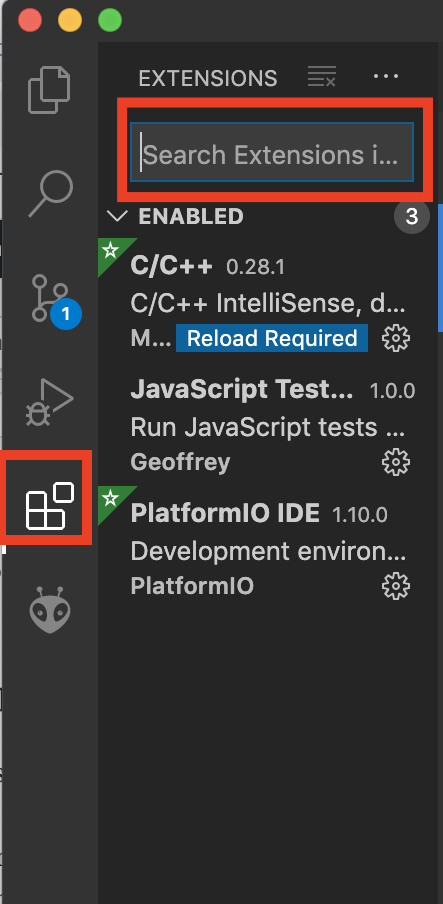
Feel free to skip this paragraph if you already use Platform.io. For first time users however, the first thing you will need to do is to download and install Visual Studio Code or Atom. I prefer to use the Visual Studio Code as its more stable. With your Visual Studio Installed, click on the Extensions icon. Enter Platform.io in the extensions search bar and hit the install button when its in view.
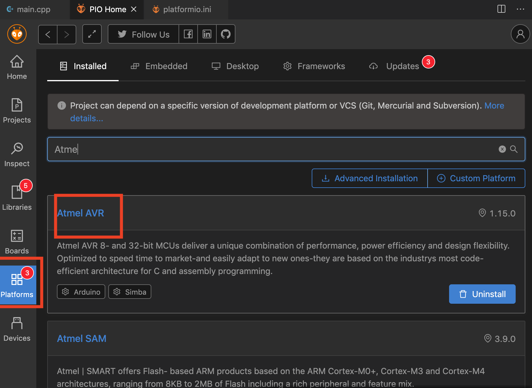
Next, we need to install the Atmel AVR Platform. With Platform.io installed, the Platform.io PIO home should automatically be launched. When it does click on the Platforms button and enter Atmel AVR into the search bar. This should bring out a list of installed/available platforms. Click the install button to install the platform. If you have used an Arduino board with the platform.io IDE before there is a good chance the Atmel AVR platform will already be installed. If this is the case, just update if necessary and move to the next step.
The Atmel AVR platform contains a number of MCU/board definitions from which you select when launching a new project. These board types along with the framework provide all the configurations that are used to compile and upload code to your microcontroller.
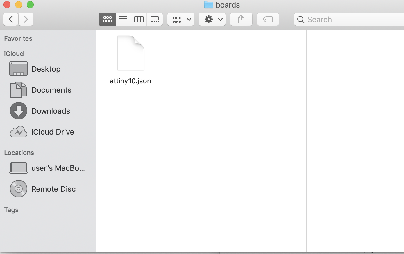
By default, the ATtiny10 board type is not listed among the board types so we need to create a custom board type for it. We do this by going to the Platform.io folder and creating a new folder named “boards” within it. In the new folder, create a JSON file named attiny10.json and copy the lines below, into the file.
You can create the file using Xcode or any editor you are familiar with. Just make sure the extension is ‘.json”. Not sure about the directory for windows users but for macOS users, the platform.io folder should be in the directory “/Users/[your username]/.platformio“. The folder is naturally hidden so you will need to press “Command+Shift+.” to show all hidden folders.
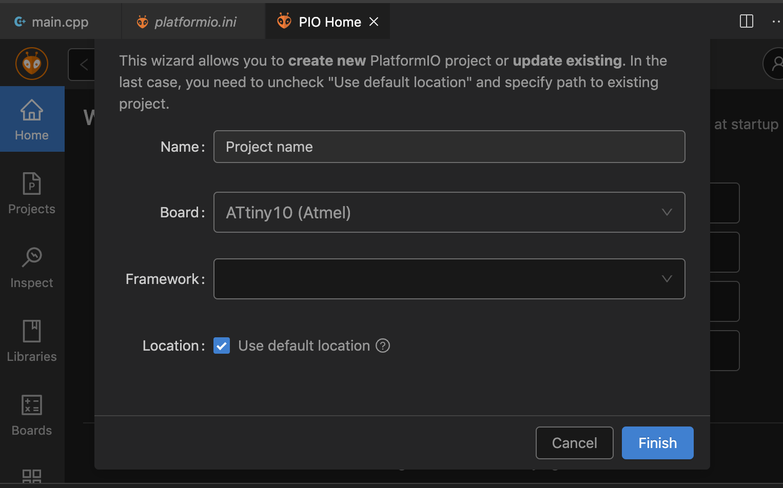
With this done, relaunch the IDE, click on the PIO home button and click on the new project option button. You should now see the Attiny10 board among the board options.
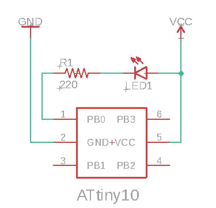
Schematics
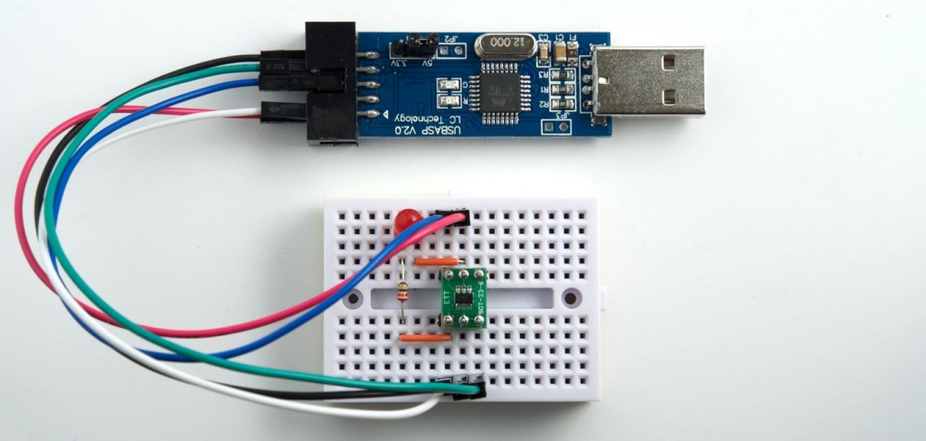
As mentioned during the introduction, for demonstration, we will implement the blink example using an LED connected to pin PB0 of the Attiny10. Connect the LED as shown in the image below;
I believe the connection is quite straightforward and easy to understand, but feel free to hit me up via the comment section if you need any clarifications.
Code
With the components connected, the next step is to write the code. As mentioned earlier the goal of the project is basically to implement the blink example to turn on/off the LED at intervals, as a result of this, the code is short and straight forward.
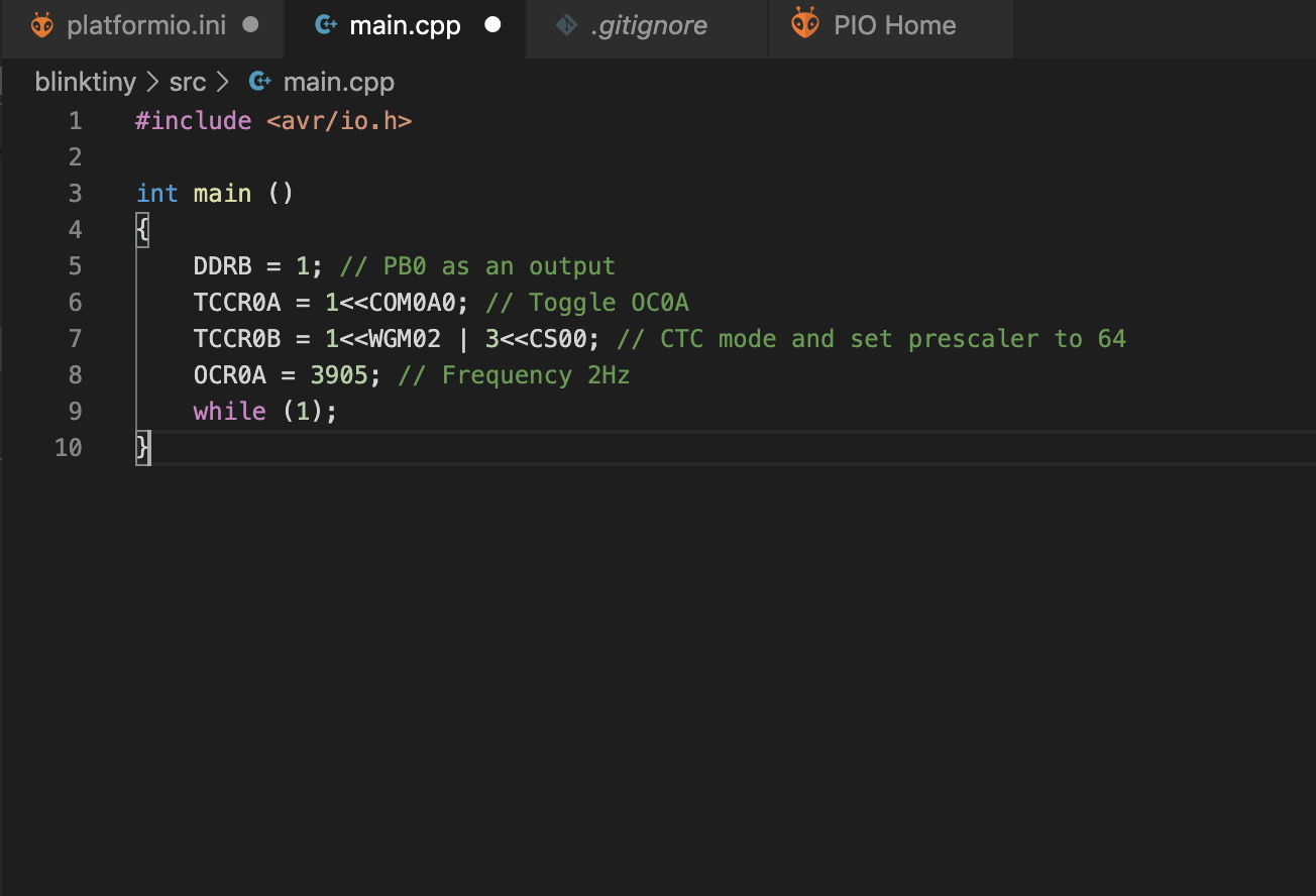
Navigate to the src. folder on the left pane of the VScode interface, the Platform.io file explorer panel, and select main.cpp file. If the file was not created automatically, right-click on src, select “new file” and name the file main.cpp. This should open an empty code (tab) where you are expected to enter your code. Enter the code below into the pane and save it.
#include <avr/io.h>

int main () {
  DDRB = 1;                    // PB0 as an output
  TCCR0A = 1<<COM0A0;          // Toggle OC0A
  TCCR0B = 1<<WGM02 | 3<<CS00; // CTC mode and set prescaler to 64
  OCR0A = 3905;                // Frequency 2Hz
  while (1);
}
The code is quite straight forward. It starts by including the avr/io library which helps with pin definitions, then follows with the main function. The main function starts with the declaration of pin PB0 to which the led is connected as output in an operation similar to the Arduino pinMode function.
#include <avr/io.h>

int main ()
{
  DDRB = 1;   //
Next, the pin is toggled using its PWM properties, the Prescaler is set to 64, and the frequency is set as 2Hz.
TCCR0A = 1<<COM0A0; // Toggle OC0A
TCCR0B = 1<<WGM02 | 3<<CS00; // CTC mode and set prescaler to 64
OCR0A = 3905; // Frequency 2Hz
The while(1) command is then called to keep it running.
while (1);

}
Uploading the Code
With the code written, we have just one final step, which is flashing it on the Attiny10. There are two parts to do this, one is connecting a programmer to the ATtiny10 and the other involves fine-tuning configurations of Platform.io.
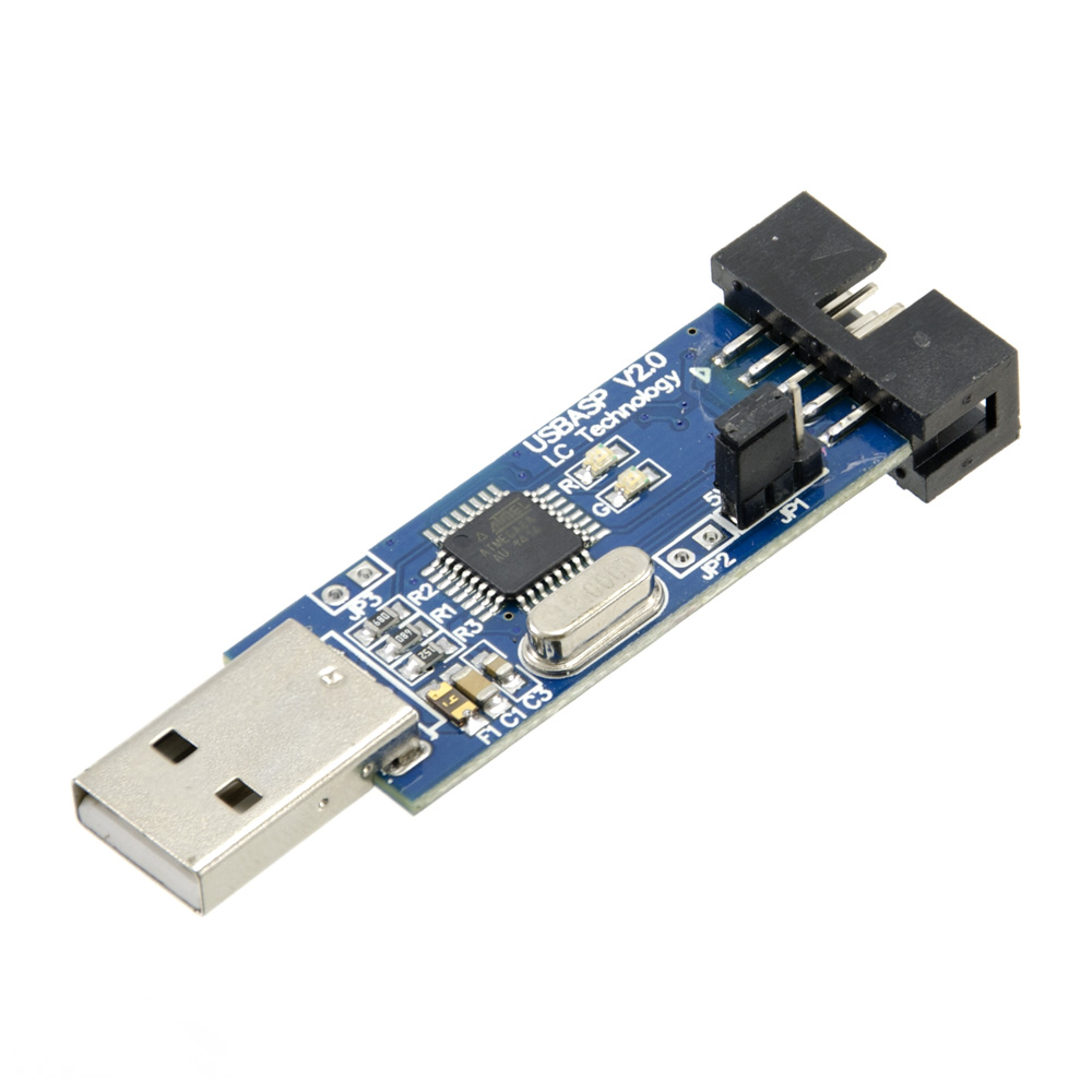
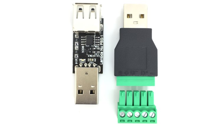
An USBASP Programmer
For the first part, while there are different types of programmers that can be used, for today’s project, we will use the fairly popular and cheap USBASP programmer which can be purchased from online electronics component stores like Aliexpress or Ebay. From my experience and that of others, most of these programmers don’t usually support the TPI protocol which is needed to program the ATtiny10, as such there is always a need to run a firmware update on the programmer.
To make it easy for the community and serve as a timeless reference resource, we covered how to update the firmware on the USBASP programmer a while back. So if this is the first time you will be using that particular programmer, check out the tutorial.
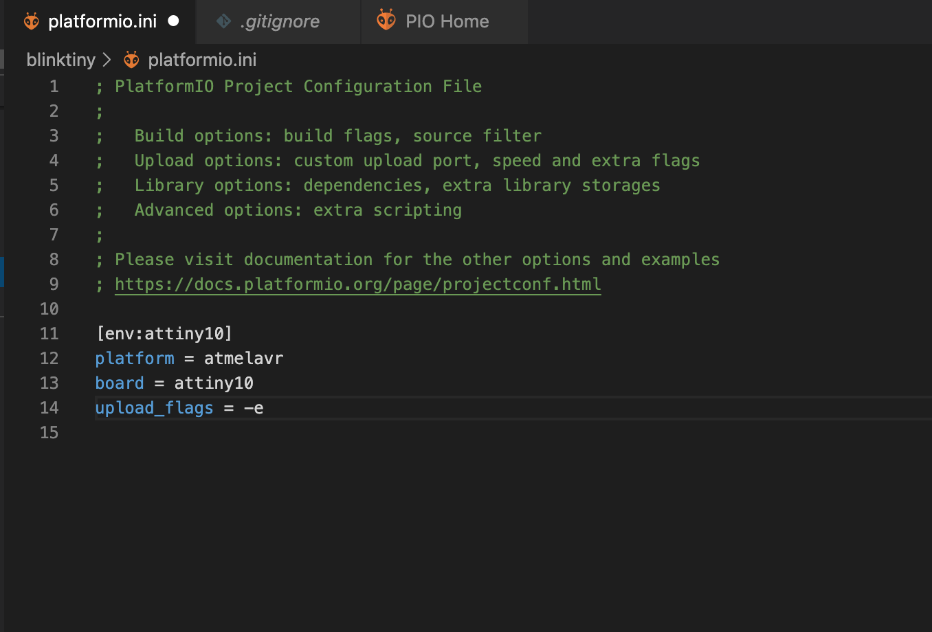
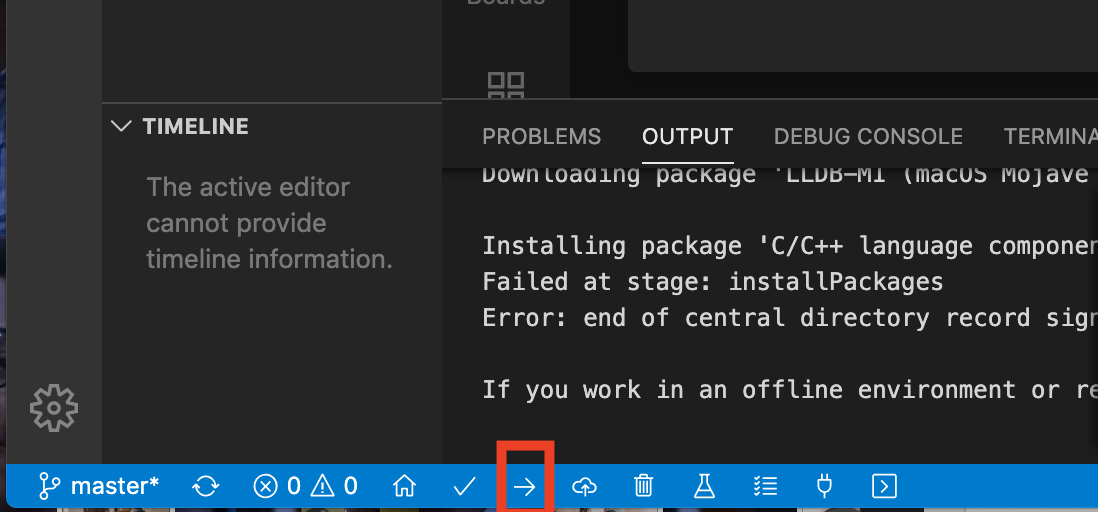
For the second part, Platform.io has different ways to flash a target device with firmware but for the sake of this tutorial, we will use the Upload button. By default, when the upload button is used, Platform.io will run the Upload task without erasing the memory. This leads to errors as the avrdude tries to verify that the code has been uploaded correctly as some part of the old program will still be in the memory. One of the good things about platform.io is the control it gives you over so many things from library version specifications to compilation configs via the platformio.ini file. To solve this problem with the upload button, add the last line in the code below to the platformio.ini file under the ATtiny10 environment.
[env:attiny10]
platform = atmelavr
board = attiny5
upload_flags = -e   ;This is the line to be added
The platformio.ini file should now look like the image below.
With this done and the USBASP connected to the microcontroller, you can go ahead and hit the upload button.
You should see the led begin to blink.
That’s it!
I Agree that this process is not very friendly to folks who are only familiar with Arduino C and not the raw C/C++ style of programming. For the ease which comes with it, I recommend the Arduino IDE route.
Feel free to reach out to me via the comments section if you have any difficulty with replicating this.
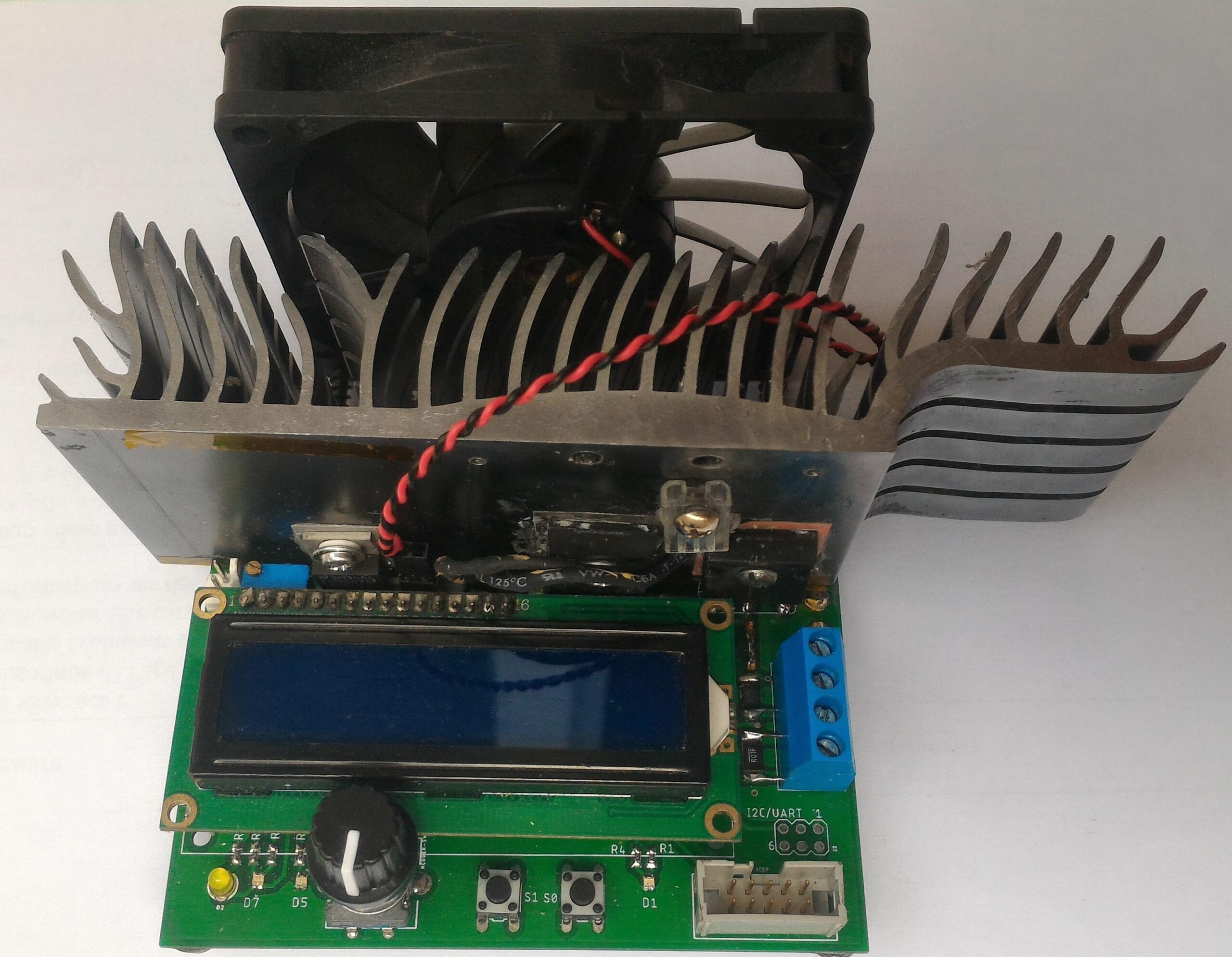
The heart of the system is an Atmel ATmega328P AVR microcontroller with 32kB of Flash and 2k of RAM running at a whopping 16MHz. It interfaces an I2C 12bit DAC (the MCP47FEB21A1) and the LTC2992 dual power monitor chip.
The USB serial interface uses the MCP2221A bridge. The display is a classic 16×2 LCD.
On the analog part, 10mΩ and 0.2Ω shunt resistors are used, coupled with two W9NK90Z N-ch power MOSFETS. The heatsink was salvaged from an old graphics card. Attached are a 10k NTC and a generic fan (12v @ 200mA, 80mm). Current regulation is achieved through the help of a MCP6H02 opamp, and a carefully designed feedback network which guarantees the specified rise time with little to no overshoot.
The layout was done using the Eagle software (v9.5.2). Gerbers, Eagle project files, top and bottom views are available on the pcb folder. PCBs were printed using JLCPCB service. The schematic is available in a pdf and Eagle .sch format as well.
Several user-definable bi-color status LEDs are included, such as Load ON/OFF, TX & RX, acquisition blink, as well as a power LED.
An expansion/debug port is provided, with +5V, ground, I2C and UART available.
There are several issues regarding the layout of the PCB, as it is a first version. Improper Kelvin connections to the current sense resistors, or wrong hole size for the power input connector by example. The heatsink originally used is salvaged from old equipement and the footprint may not be relevant to anyone else. Space for rubber feet placement should be included. Also, the LCD is too close to the heatsink, which is impractical during assembly (especially accessing the fan and temp sensor connector).
Features
Constant Current, Power and Resistance modes
Battery capacity logging with adjustable cutoff voltage
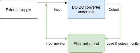
Input and output power logging : instant efficiency reading for DC-DC converters
Rotary encoder driven interface
Dedicated Load ON/OFF button
Intuitive LCD menu system with editable values
12bit current, voltage and power measurements
30W continuous sinking capability, 250W peak
Temperature controlled fan with auto shutdown.
Adjustable acquistion rate
115200 bauds serial communication through USB with a PC (non-isolated !)
Specifications
Input voltage range : 0 – 100V DC maximum, 2-80V DC regulating
Supply voltage range : 0 – 16V maximum, 12V nominal
Device current consumption : 50mA nominal (0.6W)
Load current range : 5mA – 5.25A, in 8mA steps
Current regulation : 5% +/- 8mA typical @ 8kHz bandwidth
Transient response : rise time < 20µs/A, overshoot < 2%
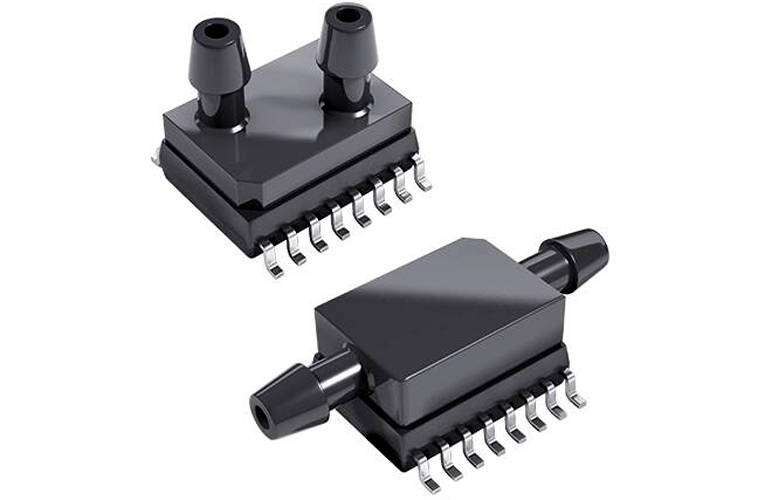
TE Connectivity has introduced a minimal footprint SMI SO-10 pressure sensor package with a vertical port. It is designed with a MEMS pressure sensor and an advanced signal-conditioning IC which is combined to provide fully pressure calibrated and temperature compensated output. The device covers gauge pressure ranges from .5 to 30PSI with a digital (I2C) or dual output (digital and amplified analog) signal with ±1% FS accuracy.
The pressure sensor’s housing is designed with a standard surface mount technology and has a JEDEC compliant SO-10 footprint for straight forward PCB design assembly. The new TE sensors are more reliable and have a robust unibody design to eliminate the opportunities for leaks. The SO-10 package offers media compatibility achieved through backside die pressurization for easy integration. The pressure sensor can be easily mounted onto the PCB board.
The SM1000 (up to 30PSI) and SM4000(up to 15PSI) have a compact design and they are suitable to be used in harsh environmental conditions. The new pressure sensors are suitable to be used in medical, industrial, and HVAC applications such as ventilation device, patient monitor, air quality tester, Multigas analyzer, Emission analyzer, Manometer, Calibration equipment, and humidity detector. More information about the SM1000(up to 30PSI) and SM4000(up to 15PSI) can be found on the official website of TE connectivity.
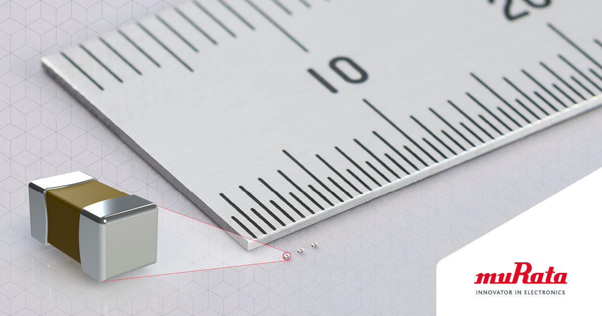
Murata Electronics today announced the availability of the GRM011R60J104M, the world’s first multi-layer ceramic capacitor (MLCC) that features a maximum capacitance of 0.1µF in a 008004 (0.25×0.125mm) package. The solution also delivers a capacitance tolerance of ±20 percent, usage temperature range of -55°C to 85°C, and rated voltage of 6.3Vdc.
By using proprietary ceramic and electrode material atomization and homogenization technology, Murata achieved a mounting surface area approximately half the size and a volume (LxWxH) approximately 80 percent smaller than conventional products in a 01005 package. Additionally, the GRM011R60J104M has nearly 10 times the capacity of similarly-sized products.
The demand for smaller and higher density electronic circuitry is growing exponentially as 5G smartphones and devices such as wearables become more widespread, multifunctional, and compact. For example, higher end smartphones alone are generally equipped with 800 to 1,000 components. With MLCCs being critical in this circuitry, it is necessary for them to be as miniaturized and powerful as possible.
PowerEver is a tiny electronic board that will keep your commercial power bank running non-stop while minimizing self-drained current. It is user adjustable and is compatible with nearly all power banks in the market. This means that your power bank will never run short of mobile power for your electronic gadget.
This board is perfect for electronic enthusiasts, field engineers, and students as well as anyone needing a mobile power supply using commonly available power banks. Help save the environment by maximizing power bank usage, especially for older models that cannot provide enough power to mobile phones but are still usable with less current-hungry electronic devices. For example an Arduino, ESP8266 and more.
Features
Use generic mobile phone power banks as a regular DC 5V power supply for powering all kind of gadgets and electronic boards
User adjustable through button triggering to suit almost all power banks
Designed to consume a self-drained current as low as possible
Small and light-weight enough to put into your wallet
Fully open source with complete schematic and source code provided for immediate tweaking
Specifications
Micro Controller
ATTiny13A running 1.2 MHz at 5V
Power
5VDC powered by any mobile power bank
Adjustable total current drain from 110 mA down to 3 mA (16.5 mA as default)
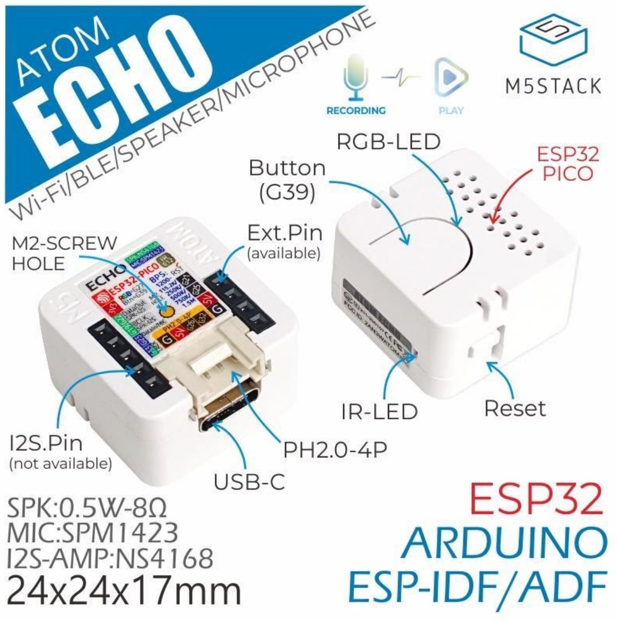
M5Stack ATOM ECHO is a tiny programmable smart speaker. Its design is based on the M5ATOM series of products. The slim design has a dimension of 24×24 and is 17mm in height. Its premium finish gives it a professional look and makes it easy to carry anywhere.
M5Stack ATOM ECHO can be programmed to be voice-controlled, which means that when it is powered on, the program is uploaded. You can simply ask for things like music, news, information, and more. Input your voice through the microphone of M5Stack ATOM ECHO, and output the text in your device using text to speech APIs. It could also be programmed to control compatible smart devices in your home with just the sound of your voice. For best results, you can program it to access AWS and other cloud platforms.
The speaker has an integrated RGB LED light (SK6812), which can visually display the connection status. As a smart speaker, it can control the ATOM series. You can connect devices through the grove interface. Pins G21/G25 can be used for general-purpose I/O, they do not support I2C and UART however. Screw holes on the back are convenient for users to affix the device in place.
The factory default firmware is a bluetooth speaker, which uses A2DP protocol to transmit audio data(call reception is not supported). After power on, the red LED will be displayed. When the connection with the bluetooth device is established, the LED will turn green. While the sound can be output from M5Stack ATOM ECHO. The LED turns red when disconnected. The firmware is compiled on the ESP-IDF platform.
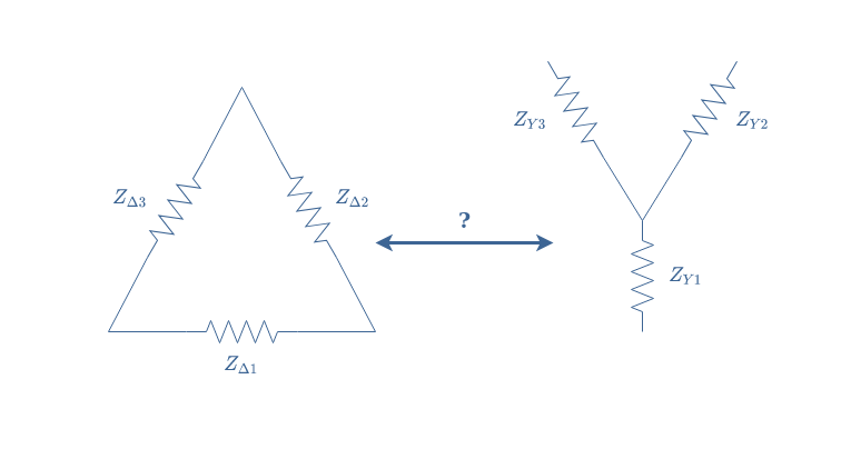
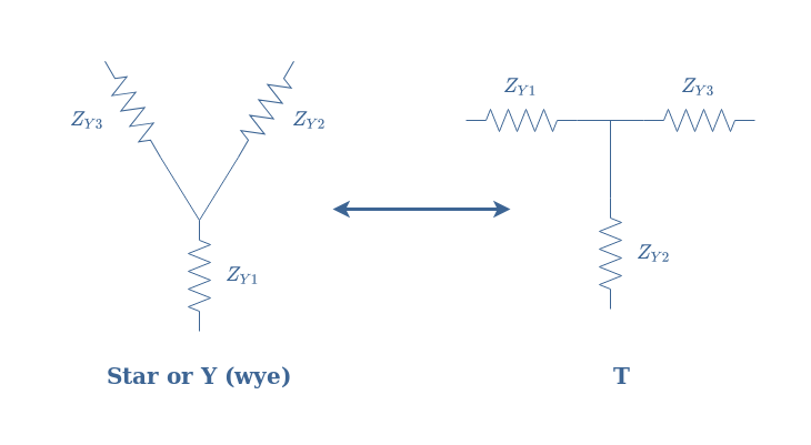
This article will focus on an electronic transformation of circuits known as star-delta transform or Y-Δ transform, which names come from the shape of the circuits involved and presented in Figure 1. The goal of this article is to understand how to transform a Y configuration to a Δ configuration and reciprocally, in which context this transformation is useful and why.
fig 1: Presentation of the Delta and Y topologies
First of all, we present the domain in which such topologies are usually found: in three-phase power circuits. We will briefly describe its functioning and advantages in comparison to the mono-phase circuits.
In the second section, we give more details about the Y and Δ configurations. We will see that such configurations are found both at the source and reception stages of three-phase circuits.
The third section focuses on the Y to Δ and Δ to Y transformations. We will illustrate the theory with some examples and explain how this transformation can simplify the study of three-phase circuits.
Presentation
We highlight in this section the difference between single-phase and poly-phase electric configurations. The reader can refer to the Sine Waveform tutorial where we have already presented some key information.
Single-phase configuration
A single-phase configuration refers to the fact that the production, distribution, and reception of the power is realized with only one AC signal.
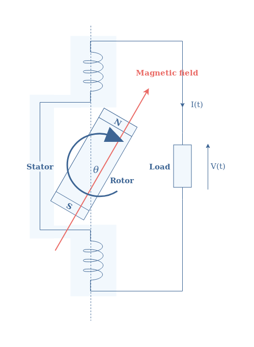
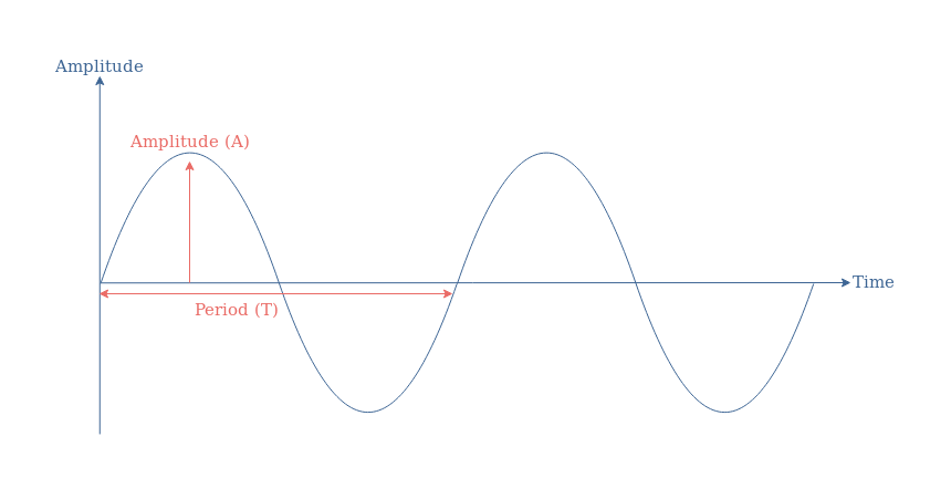
fig 2: Illustration of a single-phase power configuration
As we can see in Figure 2, only one pole-pair is present in the stator of the alternator, which generates only one AC signal or phase of the following shape:
In a single-phase configuration, as explained in the AC Power tutorial, the power transmitted to the load has a constant and a time-varying term:
eq 1: Instantaneous power in a single-phase configuration
VRMS and IRMS are respectively the voltage and current root mean square values. ΔΦ represents the phase difference between the voltage and current signals and ω their common angular pulsation.
The major problem of single-phase power configurations is that the alternating power term can cause the destruction of the output alternator by causing oscillations in the drive shaft.
For this reason, it is necessary for high-power applications to rely on a poly-phase generation system.
Poly-phase configuration
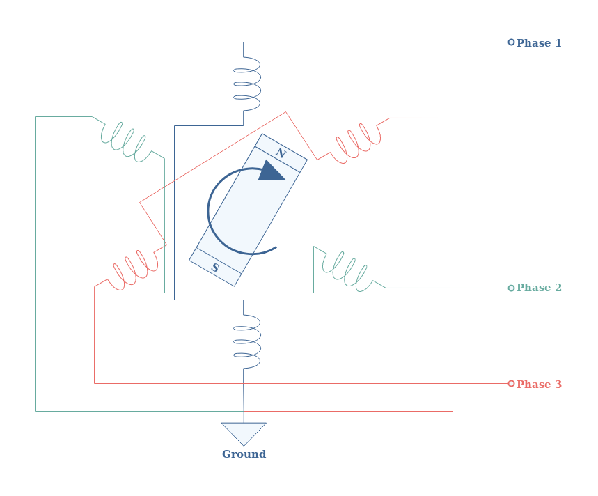
In a poly-phase configuration, many AC signals (voltage or current) are generated by a source, transported, and received by a load. The number of phases depends on the number of pole-pair coils that can be found in the stator of the alternator. Worldwide, the choice of three phases has been adopted, such as illustrated in Figure 3 below:
fig 3: Illustration of a three-phase power configuration
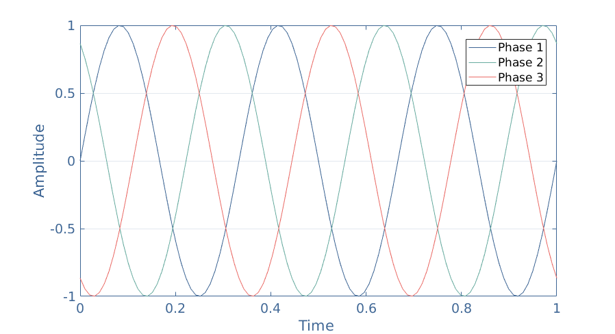
In such a configuration, each pole-pair is separated from a 120° angle, which also results in a time phase-shift of the same value:
fig 4: Resulting signals of a three-phase generation
When N phases are phase-shifted equally of 360°/N, we say that speak of balanced three-phase system.
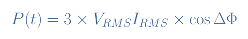
Getting the expression of the instantaneous power for a three-phase configuration is not complex but it involves a lot of repetitive and long steps. It can be shown however that the final expression of the instantaneous power is no longer depending on the time parameter, as shown in Equation 2:
eq 2: Instantaneous power in a three-phase configuration
The pulsating term of power encountered in Equation 1 for single-phase configurations is in fact canceled for any n-phase configuration with n≥2.
Poly-phase systems present other advantages such as a better power transmitted/mass of cables ratio used.
Three-phase connections
In this section, we give more details about the networks presented in Figure 1.
Y configuration
It is worth to mention that we can find many names in order to describe this topology. The star, Y (or wye), and T network all refer indeed to the same topology, depending on how the circuit is drawn:
If we actually focus on how the coils are interconnected in Figure 3, we can see that they are all connected to a grounding node. In fact, the connection used as an example in Figure 3 is a Y configuration.
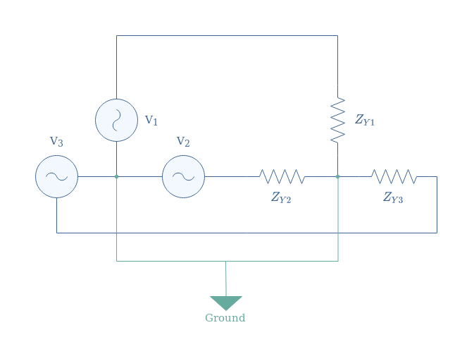
A complete Y three-phase system consists of sources, lines, and receptors (impedances) such as presented in the following Figure 5:
fig 5: Three-phase system in Y configuration
Due to the presence of ground, in a star configuration, every coil of the motor sees a reduced voltage (divided by √3).
Let’s consider a Y three-phase system in which ZY1=ZY2=ZY3=25 Ω and the sources are supplied with a 3×120 V AC signal, we suppose that cos(φ)=1. Since the impedances are equal, the voltage in each resistor is given by 120/√3=69 V. The same remark is valid for the current, their value is equal and given by 69/25=2.8 A.
The active power, according to Equation 2, is finally given by P=3×69×2.8=580 W.
Δ configuration
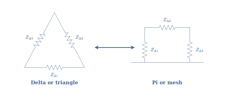
Such as for the Y configuration, many names refer to this topology: Delta (or Δ), triangle, Pi (or Π), or mesh.
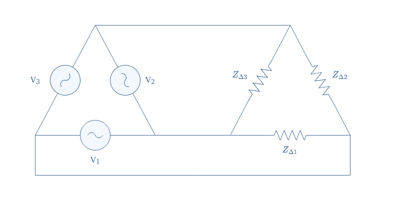
A complete Δ three-phase system consists of sources, lines, and receptors (impedances) such as presented in the following Figure 6:
fig 6: Three-phase system in Δ configuration
We can note that no grounding is present in a Δ configuration, for this reason, every coil of the motor sees directly the voltage applied.
We reconsider the same example than given previously with ZΔ1=ZΔ2=ZΔ3=25 Ω and supply of 3×120 V. In Δ configuration there is no ground, for this reason, the voltage across each resistor is equal to the supply of 120 V. The RMS intensity in each line is given by 120/25=4.8 A.
The active power is therefore given by P=3×120×4.8=1730 W.
For the same impedances and supply, the Δ configuration is more powerful than a Y configuration by a factor 3.
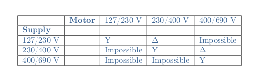
The choice of a Y or Δ configuration depends on the value of the supplied voltage and the nominal voltage of the motor used. The voltages are written for example 230/400 V which signifies that 230 V is the voltage between phases and 400 V between a phase and the ground.
The Y configuration is chosen when the supply and nominal voltages are equal, the Δ when the phase-to-ground supply is equal to the phase-to-phase of the motor. Moreover, some associations are impossible and given in the following table:
Y-Δ and Δ-Y transformations
These transformations allow us to convert a Y to a Δ configuration and reciprocally. We can also refer to these conversions as Kennelly’s theorem. The impedances present in the circuits will be labeled exactly such as formally presented in Figure 1.
Y-Δ
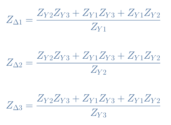
The transformations Y-Δ and Δ-Y simply consist of a series of formulas to follow. For the Y-Δ conversion, we proceed such as:
equations 3: Y-Δ transformation formulas
Δ-Y
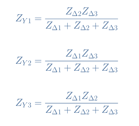
For the reciprocal formulas used for the Δ-Y transformation, we proceed such as:
equations 4: Δ-Y transformation formulas
Application
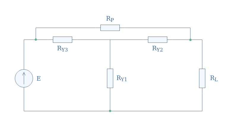
Let’s consider the following circuit of Figure 7 for which we want to find the equivalent resistance:
figure 7: Y-based circuit
We recognize in between the green nodes a Y configuration formed by the resistor RY1, RY2, and RY3. In order to find the equivalent resistance of this circuit, we transform the Y configuration by a Δ structure formed by the resistor RΔ1, RΔ2, and RΔ3 which formulas are given by Equations 3.
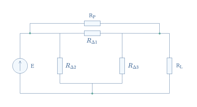
figure 8: Δ-based transformed circuit
Finally, the equivalent resistance Req is given by associating the remaining resistors in parallel: Req=[(RP//RΔ1)+(RL//RΔ3)//RΔ2].
Conclusion
This tutorial has focused on two special connections that can mostly be found in three-phase circuits, known as Star, Y, or T configuration and Δ, Triangle, or Π configuration. The goal was to understand in which context, how, and why these two configurations can reciprocally be converted from one to another.
Three-phase circuits are first of all discussed, we have seen that they are more suitable for high-power applications since a problematic pulsating term that can damage an output engine is present in single-phase circuits and eliminated with poly-phase generation.
After presenting the context, we give more details concerning the Y and Δ configurations. These configurations are actually found in poly-phase systems both at the generation and reception stages. We highlight the fact that a Δ configuration gives more active power than a Y connection. Moreover, the choice of the connection depends both on the available supply of the network and the required supply for the engine to be driven.
The Y to Δ and Δ to Y transformations formulas are presented in the last section. An application shows a typical example in which a Y to Δ transformation is used in order to simplify the process to retrieve an equivalent resistance of a given circuit.