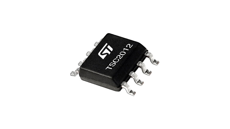
The TSC2010, TSC2011 and TSC2012 are precision bidirectional current sense amplifiers. They can sense the current thanks to a shunt resistor over a wide range of common-mode voltages, from – 20 to + 70 V, whatever the supply voltage is. They are available with an amplifier gain of 20V/V for TSC2010, 60 V/V for TSC2011 and 100 V/V for TSC2012.
They are able to sense very low drop voltages as low as 10 mV full scale minimizing the measurement error. The TSC2010, TSC2011 and TSC2012 can also be used in other functions such as: precision current measurement, overcurrent protection, current monitoring, and feedback loops.
This device fully operates over the broad supply voltage range from 2.7 to 5.5 V and over the industrial temperature range from -40 to 125 °C.
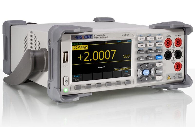
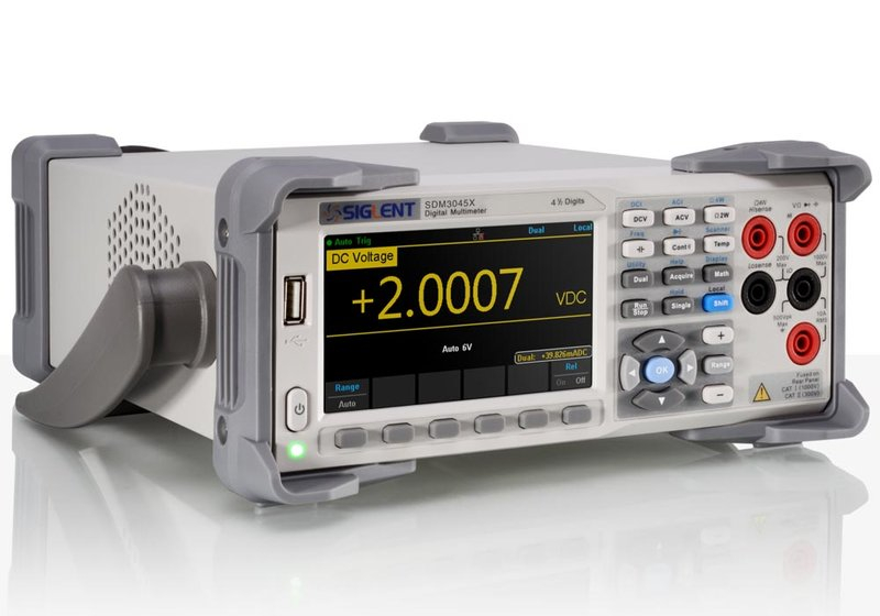
RS PRO RSDM3045X Digital Multimeter with 4 digits readings resolution (RSCAL)
Introducing the RSDM3045X digital multimeter from RS PRO, a highly reliable digital multimeter designed with 4 (66000 count) digits readings resolution and dual-display, ideal for high-precision, multifunction and automatic measurement. This multimeter features a clear and precise 4.3″ TFT-LCD display and user-friendly interface, providing an excellent user experience. The interface includes as standard: USB device, USB host, LAN. This durable electrical tester includes true-RMS AC Voltage and AC Current measurement features, with a 1GB Nand flash size for mass storage configuration files and data files. Also included is a built-in cold terminal compensation for thermocouple, offering a versatile meter for use in a wide range of applications.
Features and benefits
Real 4 digits readings resolution (66000 count)
Up to 150 rdgs/s measurement speed
True-RMS AC Voltage and AC Current measuring
1Gb Nand flash size, Mass storage configuration files and data files
Built-in cold terminal compensation for thermocouple
Easy, convenient and flexible any sensor measurement control software: Ultra Sensor
Standard interface: USB Device, USB Host, LAN
Support remote control via commands and compatible with commands of main stream multimeters
Built-in help system for enhanced user experience and troubleshooting
File management (support for U-disc and local storage)
Application
Digital Multimeters are a type of measurement device used to test and measure a range of electrical properties such as voltage (volts), current (amps) and resistance (ohms). Using a digital output readout, the digital multimeter is connected to a device and measures typically the voltage and any resistances, giving you an output you can measure. Digital multimeters offer a wide range of AC and DC measurement capabilities to suit a variety of applications. Multimeters are essential tester tools for carrying out electrical work from home renovations to large scale installations.
They are commonly used in applications such as:
While browsing through the internet to check up on the latest air quality sensors for use in a project I am working on, I stumbled across the Sensirion environmental sensor shield. Examining the features of the Kit I stumbled on an interesting project based on this Kit. The project was built by an element14 user named Shabaz and I thought a step by step build process for the project might be useful, so today’s project will be based on this.
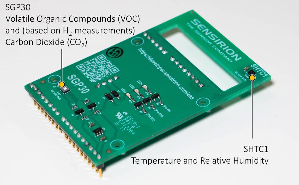
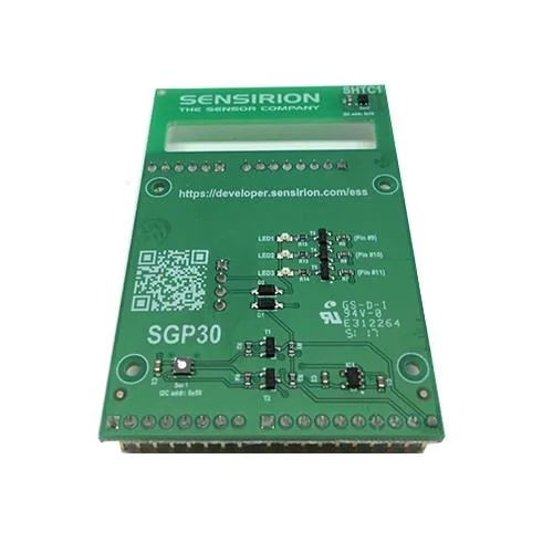
The Sensirion Environmental Sensor Shield (ESS) is a sensor shield that features the Sensirion SHTC1 humidity and temperature sensor along with an SGP30 total VOC and CO2eq sensor. It is designed for use with any microcontroller that supports I2C, and the shield is designed in line with Arduino shield footprints making it ready for use in your Arduino based projects. The board supports both 3.3v and 5v voltage levels making it ideal for 3.3v low power projects.
The demo project built by Shabaz was a part of a road test to examine the capabilities of the Sensor shield. The project, using an Arduino Micro as the microcontroller, obtains temperature, humidity, VOC, and CO2 values from the environment using the Sensor shield, and represents in on an analog scale made using the carcass of an ammeter.
At the end of this project, you would know to use the Sensation environmental sensor shield and also create a nice analog meter to present your data.
Required Components
The following components are required to build this project:
All of these components can be purchased from your local hardware store or from the attached links. The Sensirion xxx comes as a shield so, in place of the Arduino micro, you can decide to use any of the other bigger Arduino boards.
Schematics
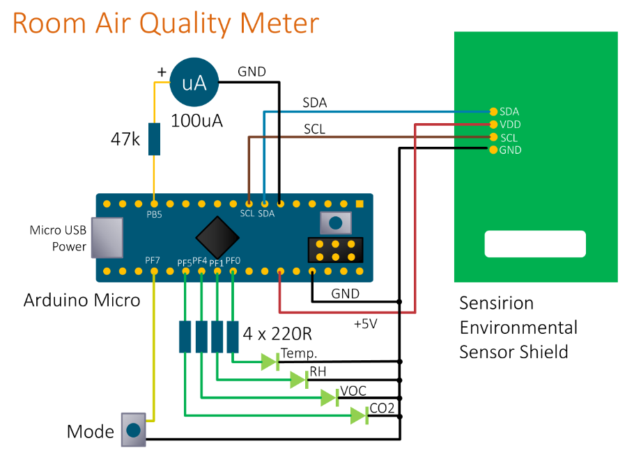
The schematics for this project is quite straightforward. The Sensirion sensor shield is connected to the Arduino micro via I2C, and other components like the LEDs to indicate the air quality level are connected in a common cathode configuration, while the positive lead of the ammeter dial/coil is connected through a 47k resistor to a PWM pin on the Micro. Connect the components as shown in the image below:
Schematics
A pin-to-pin map showing how the Sensirion sensor shield is connected to the Arduino is provided below:
Sensor Shield – Arduino
SDA - A4
SCL - A5
VCC - 5V
GND - GND
I believe connections for the other components are straightforward but if you have any issue getting up to speed on them, you can reach out to me via the comment section.
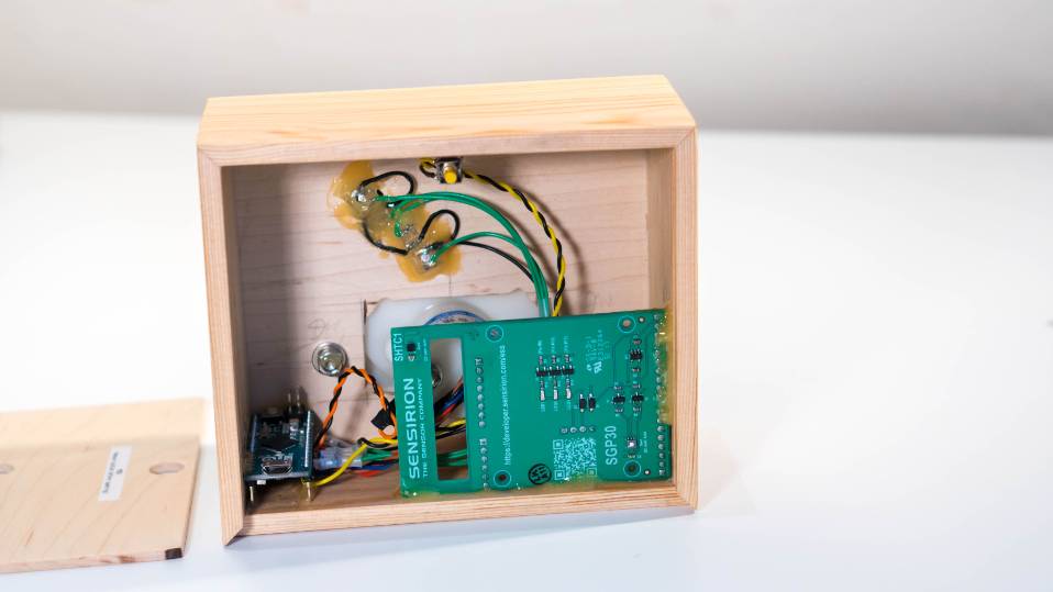
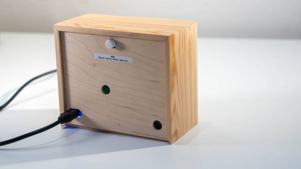
Enclosure
With the components connected, one other thing we need to do is to mount the project inside an enclosure so users can easily reference the needle points.
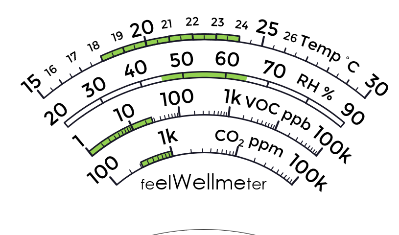
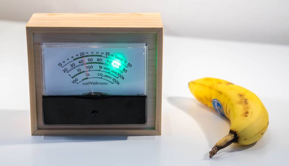
feelWellmeter scale
The enclosure adapted by Shabaz was a wooden box with the components stacked inside it. The ammeter was modified with the scale/label inside it swapped with the one that has the feelWellmeter calibration. The scale was created with the help of information from the World Health Organization‘s website and other sources to establish what values of the parameters makes for a good environment conditions. Those value ranges were shaded green on the meter scale.
One major thing to note in the enclosure is that the sensors need to be exposed to air. For a real product, this is something that needs to be considered carefully, but for this implementation, Shabaz simply made use of a 10mm diameter holes at the back of the enclosure. Sensirion has SHTxx design guidelines (PDF) which should help if you are planning to implement this on a more professional level.
The enclosure after assembly, with holes for air, is shown below.
Code
With our schematics in place and the components all wired up, the next thing to do is to write the code for the project. One of the nice things about the Sensirion Sensors shield is that it was released alongside an Arduino library with a series of examples to enable users to build projects with the shield, fairly quickly. The code for today’s project will borrow ideas from those examples so they might be worth exploring. The library can be installed directly via the library manager. Launch the library manager by going to Sketch->Include Library->Manage Libraries. On the resulting window, type Sensirion in the search box, and select “Arduino-ess”.
The idea behind the code for this project is simple. When turned on, the Arduino will fetch the data for all four parameters including; temperature, humidity, CO, and VOC from the shield and indicate their level in the air with a movement of the meter’s needle, one after the other in a cycle. For each of the parameters, one of the four LEDs will come up to indicate the parameter currently being displayed. If the attached button is pressed, the cycling will stop, and the parameters can be manually cycled by pressing the button. A further press of the button will take the device back into automatic cycle mode.
As usual, I will do a quick run through the code and post the complete version at the end of the tutorial.
The code starts with include statements for all the libraries to be used. This includes the math.h and EEPROM Library in addition to the Sensirion library. The math and EEPROM library comes pre-installed so we won’t need to download or install them.
Next, we declare variables and global constants to hold different parameters to be used in the code.
#include <math.h>
#include <EEPROM.h>
#include <sensirion_ess.h>
// *************** definitions **********************
#define meter OCR1A // PB5
#define BUTTON 18
#define LED_TEMP 23
#define LED_RH 22
#define LED_VOC 21
#define LED_CO2 20
#define LED_BOARD LED_BUILTIN
#define LED_BOARD_OFF digitalWrite(LED_BOARD, LOW)
#define LED_BOARD_ON digitalWrite(LED_BOARD, HIGH)
#define MODE_TEMP 0
#define MODE_RH 1
#define MODE_VOC 2
#define MODE_CO2 3
#define MODE_NONE 99
#define VIEW_STATIC 0
#define VIEW_DYNAMIC 1
#define DEB_NONE 0
#define DEB_TIME 1
#define DEB_TIME2 2
#define IS_PRESSED LOW
#define IS_UNPRESSED HIGH
#define DEBOUNCE_TIME 4
#define METER_TIME 2
#define VIEW_EXP 1000
#define VSIZE 8
// *************** globals and constants *************
const int led_pin[]={LED_TEMP, LED_RH, LED_VOC, LED_CO2};
int mode=MODE_TEMP;
int view=VIEW_DYNAMIC;
int fast_tick=0;
int slow_tick=0;
int led_status=0;
int button_status=DEB_NONE;
int button_time=0;
int shimmer=0;
int view_time=0;
int update_view=0;
int meter_update_timer=0;
int changed_mode=0;
int mval[4];
int vocbuffer[VSIZE]; // VOC values are low-pass filtered
int mmin=100;
int mmax=3500;
Next, we create an instance of the Sensirion library followed by a group of functions to make the project neat and readable.
SensirionESS ess;
The first function is the toggle_board_led() function which basically flashes the Arduino Micro’s onboard LED when called.
// Toggle board LED as required (used for troubleshooting)
void toggle_board_led(void)
{
  if (led_status){
  LED_BOARD_OFF;
  led_status=0;
  } else {
    LED_BOARD_ON;
    led_status=1;
  }
}
Next is the set_mode_led() function which is used to indicate which of the four parameters is being displayed.
// Set mode LED on
void set_mode_led(int mode) {
  int i;
  for (i=0; i<4; i++)
  {
    digitalWrite(led_pin[i], LOW);
  }
  if (mode<4) {
    digitalWrite(led_pin[mode], HIGH);
  }
}
Next is the signal function which is used to set the timer tick.
// *************** timer tick ************************
SIGNAL(TIMER3_COMPA_vect) // this occurs 1000 times per second
{
  fast_tick++;
  if (fast_tick>100) {
    fast_tick=0;
  }
  else {
    return; // we only want a 10 msec tick
  }

  // this code executes every 10 msec

  // blink the mode light a few times if mode has just been set to dynamic
  if (shimmer>0) {
    shimmer++;
    if (shimmer%8) {
      set_mode_led(99);
    } else if ((shimmer+4)%8) {
      set_mode_led(mode);
      if (shimmer>32) shimmer=0;
    }
  }

  // time to update the view if we're in dynamic mode?
  if (view==VIEW_DYNAMIC) {
    view_time++;
    if (view_time>VIEW_EXP) {
      update_view=1;
    }
  }

  if (button_status==DEB_NONE) {
    if (digitalRead(BUTTON)==IS_PRESSED) {
      button_status=DEB_TIME;
      button_time=0;
      if (view==VIEW_DYNAMIC) {
        view=VIEW_STATIC;
        mode=MODE_TEMP;
      } else {
        mode++;
        if (mode>3) {
          view=VIEW_DYNAMIC;
          view_time=0;
          mode=MODE_TEMP;
          shimmer=1;
        }
      }
      changed_mode=1;
    }
  } else if (button_status==DEB_TIME) {
    button_time++;
    if (button_time>DEBOUNCE_TIME) {
      button_time=0;
      if (digitalRead(BUTTON)==IS_UNPRESSED) {
        button_status=DEB_TIME2;
      }
    }
  } else if (button_status==DEB_TIME2) {
    button_time++;
    if (button_time>DEBOUNCE_TIME) {
      button_time=0;
      button_status=DEB_NONE;
    }
  }

  if (changed_mode)
  {
    set_mode_led(mode);
  }
}
It is followed by the Manual_debounce function which is used to filter out noise in button press.
Next is the cal_mode function, which is essentially used to calibrate the sensor readings with the meter. The minimum and maximum values are stored in the EEPROM.
void cal_mode(void)
{
  int i, j, k;
  int maxval, minval;
  minval=0;
  maxval=4500;
  int wait_press=1;
  for (k=0; k<4; k++)
  {
    digitalWrite(led_pin[k], HIGH);
  }
  manual_debounce();
  while(wait_press) {
    for (i=3500; i<4500; i=i+10) {
      meter=i;
      for (j=1; j<200; j++) {
        delay(1);
        if (digitalRead(BUTTON)==IS_PRESSED) {
          maxval=i;
          i=4500;
          j=9999;
          wait_press=0;
          digitalWrite(led_pin[3], LOW);
        }
      }
    }
  }
  manual_debounce();
  wait_press=1;
  while(wait_press) {
    for (i=0; i<200; i=i+10) {
      meter=i;
      for (j=1; j<200; j++) {
        delay(1);
        if (digitalRead(BUTTON)==IS_PRESSED) {
          minval=i;
          i=900;
          j=9999;
          wait_press=0;
          digitalWrite(led_pin[2], LOW);
        }
      }
    }
  }
  manual_debounce();
  // write minval and maxval into EEPROM
  EEPROM.write(0x01, (minval & 0x00ff));
  EEPROM.write(0x02, ((minval>>8) & 0x00ff));
  EEPROM.write(0x03, (maxval & 0x00ff));
  EEPROM.write(0x04, ((maxval>>8) & 0x00ff));
  EEPROM.write(0x00, 0xaa);
  digitalWrite(led_pin[2], HIGH);
  digitalWrite(led_pin[3], HIGH);
  delay(1000);
  set_mode_led(99);
  mmin=minval;
  mmax=maxval;
}
Next, are the functions used in fetching the latest value of the parameters being measured including the VOC, the temperature, the Relative humidity, and the CO2.
// calculate the moving average
int vocavg(void)
{
  int i;
  int tot=0;
  for (i=0; i<VSIZE; i++) {
    tot=tot+(vocbuffer[i]/VSIZE);
  }
  return tot;
}

// support a min temperature of 15 deg C, and a range of 15 deg C (i.e. max will be 30 deg C)
int temp2pwm(float x)
{
  int p;
  if (x>30.5) x=30.5; // max temperature will be off the scale by 0.5 deg C
  x=x-15.0; // min temperature to be displayed will be 15 deg C
  p=(int)((((float)(mmax-mmin))/15.0)*x);
  p=p+mmin;
  return(p);
}

// support a min RH value of 20%, and a range of 70% (i.e. max will be 90%)
int rh2pwm(float x)
{
  int p;
  if (x>92.0) x=92.0; // max RH will be off the scale by 2%
  x=x-20.0; // min RH to be displayed will be 20%
  p=(int)((((float)(mmax-mmin))/70.0)*x);
  p=p+mmin;
  return(p);
}

// support a VOC range from 1 to 100k ppb on a log scale
// log(1) is 0, log(100k) is 5
int voc2pwm(uint16_t x)
{
  double i;
  int p;
  i=log10((double)x);
  p=(int)((((float)(mmax-mmin))/5.0)*((double)i));
  p=p+mmin;
  return(p);
}

// support a CO2 range from 100 to 100k ppm on a log scale
// log(100) is 2, log(100k) is 5
int co22pwm(uint16_t x)
{
  double i;
  int p;
  i=log10((double)x);
  i=i-2.0; // min to be displayed is 100, i.e. 10^2.0
  p=(int)((((float)(mmax-mmin))/3.0)*((double)i));
  p=p+mmin;
  return(p);
}
With this done, we move to the void setup function.
The function starts with the initialization of serial communication so the serial monitor can be used for debugging purposes and the declaration of pinMode of the pins to which LEDS and the pushbutton are connected.
// *************** setup code ************************
void setup() {
  int i;

  Serial.begin(9600);
  delay(1000); // let console settle

  // Set LEDs as outputs
  for (i=0; i<4; i++)
  {
    pinMode(led_pin[i], OUTPUT);
  }
  pinMode(LED_BOARD, OUTPUT);

  LED_BOARD_OFF;

  // set up button
  pinMode(BUTTON, INPUT_PULLUP);
Next, we configure the PWM properties of the pin to which the meter is connected and perform calibration based on the state of the button.
// start up PWM mode on the meter output pin
  meter=0;
  DDRB |= 0x20; // set PB5/OC1A pin as output
  ICR1 = 4000;  // freq set for 500Hz. ICR1 = (16M/8)/freq = 2M/freq
  TCCR1A = 0x82; // clear OC1A on compare match
  TCCR1B = 0x1a; // clkio divided by 8, mode 14 waveform: fast PWM, top is ICR1

  // is button pressed at power-on?
  if (digitalRead(BUTTON)==IS_PRESSED) {
    cal_mode();
  } else {
    if (EEPROM.read(0x00)==0xaa)
    {
      i=EEPROM.read(0x02);
      i=i<<8;
      mmin=i|(EEPROM.read(0x01) & 0xff);
      i=EEPROM.read(0x04);
      i=i<<8;
      mmax=i|(EEPROM.read(0x03) & 0xff);
      // sanity
      if ((mmin<0) || (mmin>200)) mmin=100;
      if ((mmax<3000) || (mmax>4500)) mmax=3500;
    }
  }
Finally, we initialize the sensor shield and proceed to the void loop() function.
 // light up the mode indication
  set_mode_led(mode);

  // initialize sensors
  ess.initSensors();

}
The void loop function is quite straightforward thanks to the functions created earlier.
It starts with the initialization of local variables to hold humidity temperature and CO and VOC. Next commands from the Sensirion library to get readings from the sensor shield into the local variables that we created.
void loop() {
  int i;
  float tf, hf;
  uint16_t vu, cu;

  // perform measurements, and convert to a PWM width value
  ess.measureIAQ(); // measure first to ensure proper timing
  ess.measureRHT();
  tf=ess.getTemperature();
  hf=ess.getHumidity();
  vu=ess.getTVOC();
  cu=ess.getECO2();
  mval[0]=temp2pwm(tf);
  mval[1]=rh2pwm(hf);
  mval[2]=voc2pwm(vu);
  mval[3]=co22pwm(cu);
  delay(ess.remainingWaitTimeMS());

  toggle_board_led(); // just as an internal heartbeat indicator
Depending on the mode (based on button press) we update the meter’s needle with the new values and also print the values on the serial monitor.
// if in dynamic view setting, then the mode is updated periodically
  if (update_view)
  {
    update_view=0;
    view_time=0;
    mode++;
    if (mode>3) mode=0;
    set_mode_led(mode);
    if (mode==MODE_VOC) changed_mode=1;
  }

  // update the meter needle
  if (changed_mode)
  {
    changed_mode=0;
    if (mode==MODE_VOC) {
      // set the VOC filter buffer
      for (i=0; i<VSIZE; i++) {
        vocbuffer[i]=mval[mode];
      }
    }
  }

  if (mode==MODE_VOC) {
    append_vocbuffer(mval[mode]);
    meter=vocavg();
  } else {
    meter=mval[mode];
  }

  // output the values via serial, as a sanity check
  Serial.print("Temp: ");
  Serial.print(tf);
  Serial.print("Hum: ");
  Serial.print(hf);
  Serial.print("VOC: ");
  Serial.print(vu);
  Serial.print("CO2: ");
  Serial.print(cu);
  Serial.println();
}
That’s all. The complete code for the project is attached under the download section.
Demo
With the code complete and the hardware setup in place, we can now upload the code to the device. Connect the device to your computer via a USB Cable. Hit the verify button to ensure you have all the libraries installed and there are no errors. With this done successfully, hit the upload button. Your “feelWellmeter’ should now be live.
Demo
To calibrate the meter, hold down the button at power on. The device will go into the calibration model with the needle moving slowly. Once the needle gets to the point you wish to consider as the minimum point on the scale, press the button. This will store that particular position of the needle as the minimum point. Do the same to set the max point. Wait for the needle to get to the point you’d like to take as maximum and press the button. Per our code, this min and max value will be stored in the EEPROM and will be remembered by the device at the next bootup.
With this done, the device should now begin cycling through the parameters, moving the needle and indicating the parameter in focus with an LED.
That’s it! Your very own feelWellmeter.
Further Steps
The I2C interface possessed by the sensor shield makes it easy to connect the shield to any kind of MCU. So you could easily connect the shield to a board like the ESP32 and stream the data online, or even eliminate the complications associated with this version of the feelWellmeter and build a digital version using a TFT display.
That’s it for this tutorial. If you have issues getting any part of it to work, feel free to shoot me a comment via the comment section below.
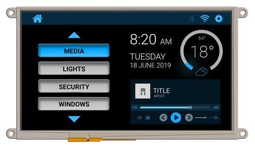
Apart from the simple and fast development of graphics applications, a larger display has been added to the pool of benefits of working with 4D Systems displays. New 9” module with resistive or capacitive touch panel and with adapters for Raspberry Pi and Arduino.
Intelligent displays with powerful (free) software for the simplest possible development of applications may already be familiar to you from several of our articles.
Display modules from 4D Systems have attracted many fans especially for the ability to easily and quickly develop an application in 4DGL (C-like) graphics or even graphically, practically by “drag and drop” method using a wide range of ready-to-use widgets.
The proprietary graphics processor (Diablo 16) provides enough power and I/O functionality to control the surrounding electronics. Thus for not very complex applications, these modules can replace the Host processor and become the core of the application.
The 4D Workshop 4 IDE development environment provides a variety of ready-to-use buttons, sliders, switches, analogue gauges and other graphics that, thanks to a touch panel, can be used to replace classic electromechanical components to simplify wiring, reduce costs and increase device reliability.
Even 4.3 ”and 7” display can accommodate a fair number of different indicators and controls to create powerful graphical manipulation (HMI). This is even truer for the new 9-inch uLCD-90DT and uLCD-90DCT, which has a 1.7x larger area than the 7-inch module.
The gen4 uLCD family design is the same for all available modules and all have a plastic white frame as well as pins on the FPC connector. However, uLCD-90 does not have an additional white plastic frame with eyelets for side mounting for screws but these eyelets are metal and are directly part of the LCD module design.
Features:
9 ” intelligent RGB display module 800×480 px
fast application development in a powerful development environment (freeware)
easy to use graphics
slot for uSD card
capable of standalone operation
single power supply 4 to 5.5V
The easiest way to connect the module to a PC and start working in the 4D Workshop 4 IDE is to use the 4D-UPA programming module.
A big advantage of 4D Systems modules is the mutual compatibility of modules and applications. The application written for the 4.3″ module can also be used for the 9″ module, but of course, it is necessary to adjust the placing of graphic elements (or add more of them) to use the significantly larger display area.
The uLCD90 is available with a resistive (uLCD-90DT) or a capacitive (uLCD-90DCT) touch panel as well as with adapters for Raspberry Pi and Arduino. The nominal supply voltage is + 5V (4-5.5V, approx. 760 mA).
Thanks to many years of cooperation with the manufacturer, we can deliver any 4D Systems product in a short time and at competitive prices.
If you need more information about 4D Systems products, SOS electronic is ready to help you at sales@soselectronic.com
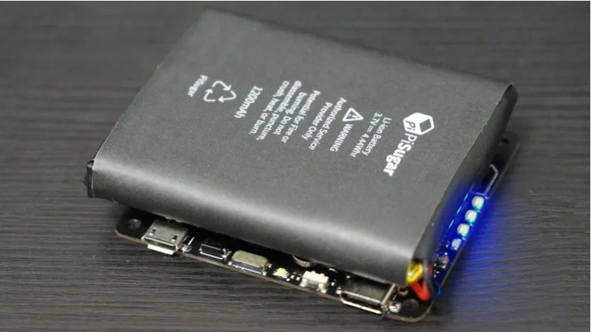
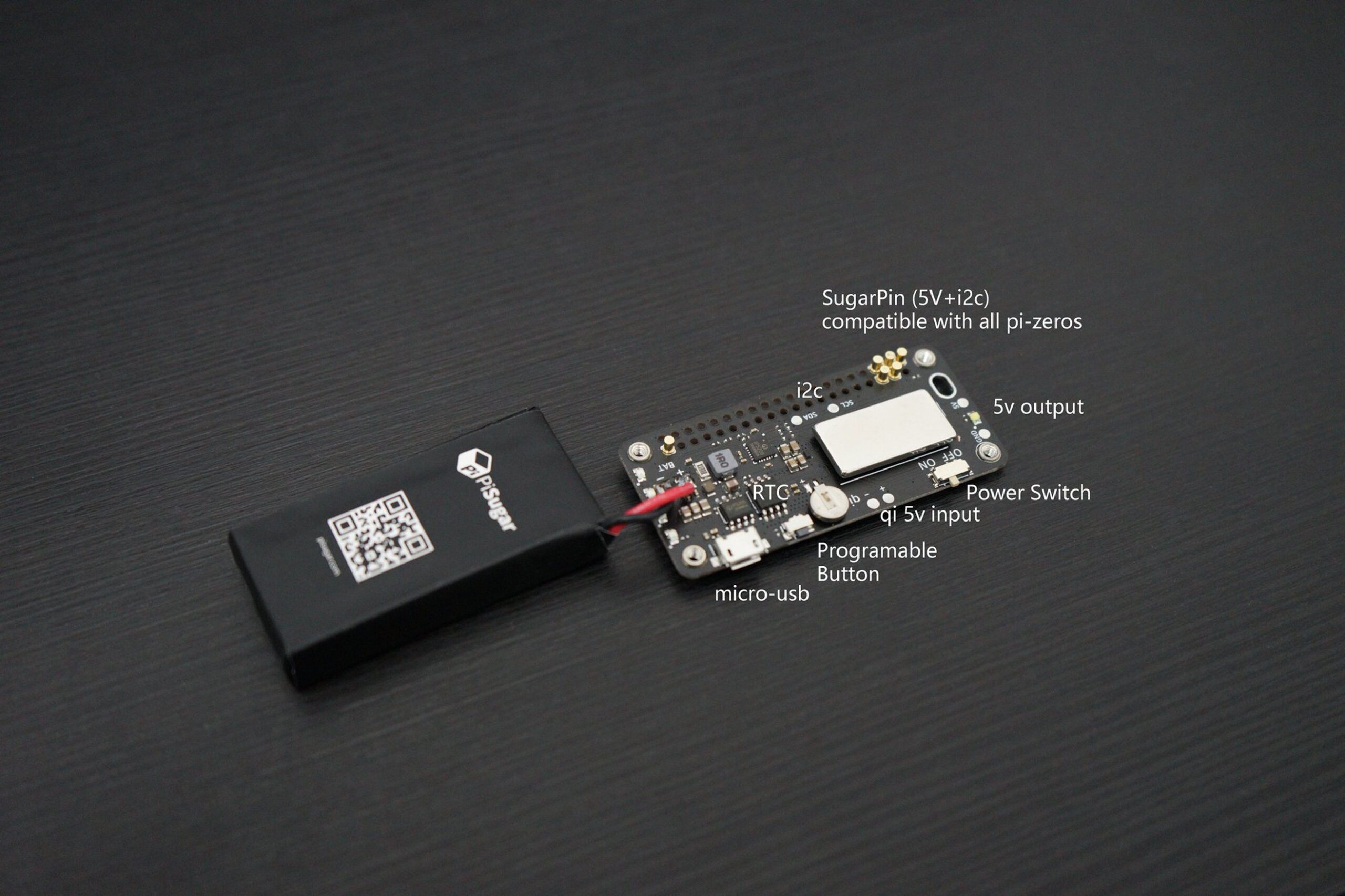
The team of engineers at the PiSugar project has launched a second-generation version of their compact battery accessory for the Raspberry Pi Zero family of single-board computers, and they call it the PiSugar2. Last year, the original PiSugarwas launched, integrating a 900mAh lithium-ion battery with a custom-built PCB designed to function with voltage test points on the underside of a Raspberry Pi Zero v1.1 or v1.3, which according to the company’s internal testing enables up to four hours of active usage per charge.
The PiSugar2 can be viewed as an evolutionary upgrade to the concept, rather than revolutionized concept. Like the PiSugar, the PiSugar2 houses a lithium-ion battery; rather than simply enabling dumb power, though, the PiSugar2 can act as a fully-functional software-driven uninterruptible power supply (UPS). The company give an explanation on the upgraded design:
“PiSugar2 support UPS function… When the external power supply is powered off, it can maintain the uninterrupted operation of the equipment, and safely shut down when the power is too low.”
This is possible through a custom “PiSugar Power Manager” application, that is configurable and can be monitored via the network.
The redesign also features additional functionality due to an on-board real-time clock (RTC), which is equipped with its own battery back-up, and can be used to power the Raspberry Pi Zero on at configurable times. PiSugar2 also features a user-programmable button, supporting press, double-press, and long-press actuation modes. The PiSugar2 is available in two variants: The PiSugar2PowerPack M utilizes a 900mAh battery and offers a peak output current of 1.2A, for a period of 3-4 hour runtime per charge; the PiSugar2 PowerPack L however, includes a 1,200mAh battery with 2.4A peak output current for a period of 5-6 hour runtime. Both are charged using an on-board micro-USB port.
The PiSugar2 is available now on the PiSugarTinde store. Price starts at $39.99 for the PiSugar2 L and $35.99 for the PiSugar2 M. More information can be found on the company’s GitHub repository.
Update:
PiSugar2 Pro
The PiSugar team recently unveiled a second new design, and this time they ditched the compact Raspberry Pi Zero footprint of its original PiSugar and upgraded PiSugar2 for a larger form factor, which offers considerably more power.
Called the PiSugar2 Pro, the latest model is built for full-size Raspberry Pi systems, including the latest Raspberry Pi 4 Model B and features a 5,000mAh battery for a period of 8-10 hours of runtime, and also a “turbo” current output of 6A, according to the company, enough to run hard drives and other energy-hungry devices. Just like the PiSugar2, the PiSugar2 Pro includes on-board real-time clock and UPS functionality. The PiSugar2 Pro is now listed on Tindie, with price at $49.99 including battery.
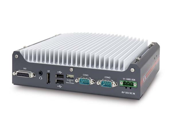
Neousys Technology, an industry-leading provider of rugged embedded systems, today announced their latest rugged fanless embedded platform, Nuvo-7531 series, featuring Intel® 9th/8th-Gen Core™ processor, compact dimensions, Gigabit Ethernet and USB ports with screw-lock mechanisms. It is an ideal solution for industrial automation, machine vision and automated guided vehicle applications.
Powered by an Intel® 9th/ 8th-Gen Core™ 65W/ 35W CPU that offers more than 50% computation performance improvement over the previous generation, Nuvo-7531 series is a fanless embedded computer with a 212 x 165 x 63 mm low-profile chassis that is compact and yet powerful.
The Nuvo-7531 has an abundance of I/O connections. It features four Gigabit Ethernet and four USB3.1 ports with screw-lock for multiple Gigabit Ethernet and USB camera connections. The screw-lock design offer rugged connectivity by ensuring the connector is screwed-on and does not fall off easily. For data storage purposes, there is a hot-swappable HDD tray for you to hot-swap the storage drive without turning off the system or dismantle the chassis. In addition, Nuvo-7531 supports three mPCIe slots for expansion so you can install WIFI or 3G/ 4G modules to achieve wireless communication. For convenience, there is a pet-door at the bottom of the enclosure for easy installation or maintenance of mPCIe and M.2 modules.
“Nuvo-7531 is a little giant in the world of rugged embedded controllers. While other embedded controllers with the same desktop i7/ i5 CPU are larger in dimensions, Nuvo-7531 offers exactly the same computing performance in just 1/2~2/3 the size. It is a better fit for applications that require high performance platforms in restricted spaces.” said Dennis Chen, Product Manager of Neousys Technology.
Overall, for a compact embedded computer, Nuvo-7531 delivers amazing computing power and provides rich I/O connectivity. It is an ideal solution for a variety of industrial applications that require a certain degree of processing power but limited by installation space and harsh environments, such as industrial automation, machine vision, robotics and automated guided vehicle.
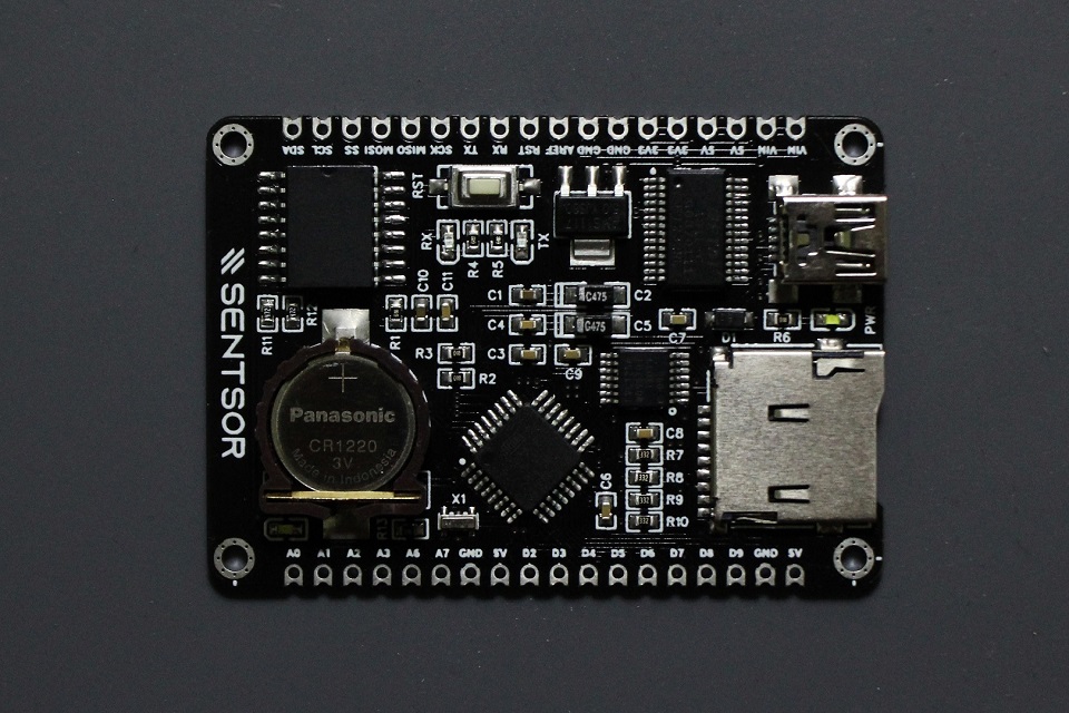
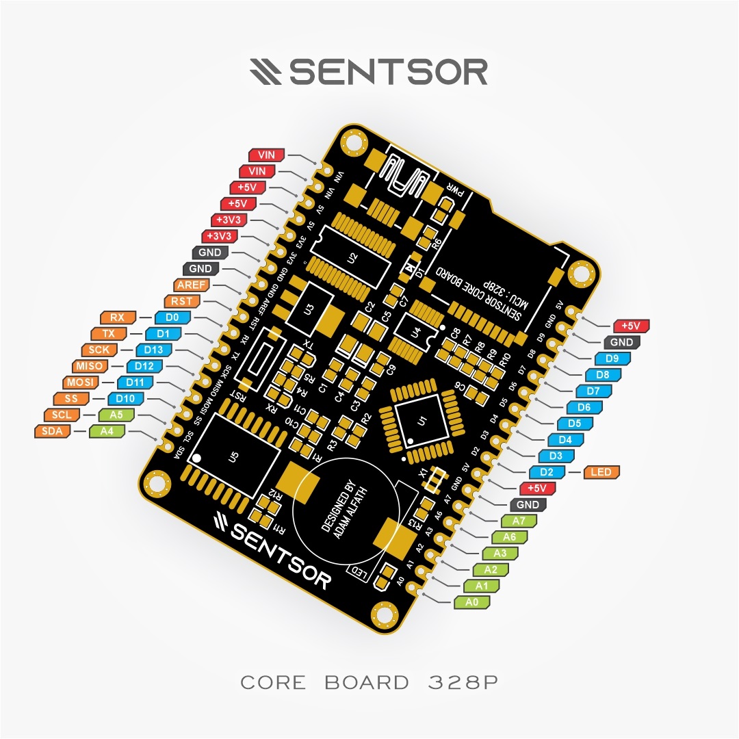
As SENTSOR moves up to offer custom development services for data needs in research and industry, the company has also provided open-source hardware products whose sources can easily be freely accessed and modified to open up as many opportunities as possible.
“How often do you face the need for data collection/datalogging, industrial monitoring equipment, Power, vibration, environment, practicum/thesis data, Measurement of temperature, current, voltage, mass, etc? Regardless of what their needs are, the data logging process always has 3 main components namely time (timestamp), storage/processing media, and the data are taken itself (usually from sensor or measurement instruments). Then how many times have you picked 3 different boards for this need? Microcontroller, RTC module and memory card adapter module, 3 components that are always present in the data logging project. Certainly very helpful isn’t it if there is a development board that has 3 functions?”
The all-in-one tiny SENTSOR 328P Core development board is one of the recent solutions by hobbyist/ electronics developer, Adam Alfath, to sensor management needs during data collection; from sensing to monitoring and finally to logging. Designed to optimize data logging in projects, the compact and powerful Core 328P development board packs in an ATMEGA328P microcontroller unit running at 16 MHz, memory card adapter for microSD size, DS3231 precision RTC with around 3.5ppm accuracy and UART-to-USB chip for connection via USB. It also has castellated holes and pin headers that provide connection options which make it easier to apply the SENTSOR Core board to each of your data logging projects.
Features of the Core 328P include:
2x 18P pin layout and pitch 2.54 mm for power, programming, and communication
About 22 GPIOs at 5V pin levels
FT232RL serial UART to USB for data connection needs via USB without installing additional drivers.
AMS1117 5V regulator
MicroSD socket (connected via SPI)
Built-in LED and,
Arduino Nano 3.0 bootloader support
Board dimensions: 5.84 x 4.06 cm
Alfath says that the Core 328p development board is open source but advises that it should be used wisely. The board is currently available for sale at IDR 200,000, about USD 13.66, and more details including schematics and guidelines on how to use it can be found on its GitHub repository.
Heilind Electronics, a leading distributor of electronic components worldwide and an authorized distributor for Amphenol Advanced Sensors, is now stocking the manufacturer’s ChipCap 2-SIP humidity and temperature sensor.
ChipCap 2-SIP offers all the features and benefits of the ChipCap 2 in a Single In-Line Package (SIP) with ready installed V-Core capacitor for easy and convenient application.
The product offers the most advanced and cost-effective humidity and temperature sensing solution, ideal for virtually any type of application. It uses an I2C interface and features alarm functions for control at minimum or maximum humidity. It is also RoHS-compliant and lead-free. Individually calibrated and tested, ChipCap2 performs at plus/minus two percent from 20 to 80 percent RH (plus/minus three percent over entire humidity range), and is ready to use without further calibration or temperature compensation.
Not only does this solution feature low current consumption, precision and accuracy, but it also allows for better air circulation and response time. ChipCap 2-SIP sensors are the ideal sensing solution for applications requiring high reliability, high accuracy and cost-effectiveness.
They are especially suited for harsh environments and a variety of medical, energy-saving HVAC control, process control and instrumentation, and automotive and transportation applications.
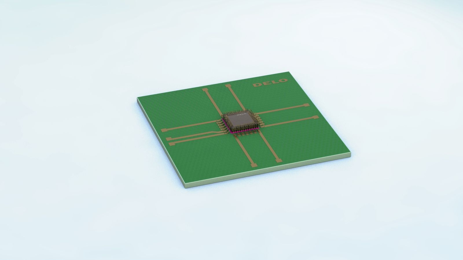
DELO has developed a new electronic adhesive that is both thermally conductive and electrically insulating and shows good strength even after standardized humidity tests with subsequent reflow cycles. DELO MONOPOX TC2270 ensures fast heat transfer and long-term reliable operation of semiconductors in power electronics.
A common reason for the failure of power semiconductors is the heat development in the often very small components, as there is usually no efficient heat dissipation. Adhesives not only ensure a permanent bond but also dissipate heat and provide electrical insulation.
The new electronic adhesive from DELO is a one-component, heat-curing epoxy resin. Due to its ceramic filler aluminum nitride it provides very high thermal conductivity of 1.7 W/(m∙K) (measured by the criteria of ASTM D5470). This is comparable with silver-filled isotropic conductive adhesives (ICA), which have a thermal conductivity of ~1.5-2.0 W/(m∙K).
One advantage of DELO MONOPOX TC2270 over ICA is that it also provides electrical insulation. The adhesive thus ensures both reliable heat dissipation and electrical insulation of assemblies. Using the new electronic adhesive additionally allows proportionate component costs to be reduced.
In cured condition, DELO MONOPOX TC2270 has a compression shear strength of 34 MPa on the FR4 composite material and of 11 MPa on high-performance LCP plastics. When bonding microchips, the electronic adhesive reaches values of 60 N in the die shear test (1×1 mm² silicon dies on gold surface). Even after standardized humidity tests, DELO MONOPOX TC2270 shows good strength. To determine the moisture sensitivity level (MSL 1), silicon dies were bonded to different PCB materials, stored for one week at 85 °C and 85 % air humidity, and then subjected to three consecutive reflow cycles. Even with these loads, the adhesive retained its high strength level.
To enable the bonding of temperature-sensitive assemblies and prevent them from damage caused by excessive curing temperatures, the adhesive has been designed with a chemical system, ensuring that final strength is reached after 90 minutes at a curing temperature of 60 °C. With a temperature of 80 °C, the curing process can be reduced to 15 minutes. In this way, production processes can be individually adapted to the component types and quantities to be manufactured. The adhesive’s service temperature range is between -40 and +150 °C.
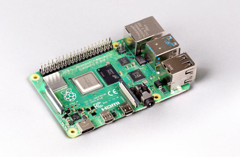
After almost one year of having the Raspberry Pi 4 around, the rumors of an 8GB RAM version of the board being in the works has finally been confirmed with a launch. Speaking about the new board, Eben Upton, CEO of the Raspberry Pi Foundation said
“While we launched with 1GB, 2GB, and 4GB variants, even at that point we had our eye on the possibility of an 8GB Raspberry Pi 4. We were so excited about the idea that the non-existent product made its way into both the Beginner’s Guide and the compliance leaflet. Today, we’re delighted to announce the immediate availability of the 8GB Raspberry Pi 4, priced at just $75”.
As opposed to sharing RAM with a built-in NPU like the Rock Pi N10 and Ficus2, the new Pi 4 model is the first ARM-based single-board computer under the $200 price to provide an 8GB RAM support entirely for the CPU.
Except for the 8GB RAM capacity, the board still maintains every other feature of the Raspberry Pi 4 including:
Broadcom BCM2711 quad-core Cortex-A72 running at 1.5 GHz
8GB LPDDR4
MicroSD card slot
2x micro HDMI ports, 2-lane MIPI DSI display port and 3.5mm AV port with composite video output and display
Gigabit Ethernet and Bluetooth 5.0 BLE
Stereo and digital audio
40-pin GPIO header
2x USB 3.0, 2x USB 2.0
5V DC via GPIO header, 5V DC via USB-C connector
Dimensions: 85 x 56 mm
The new Pi 4 model is suitable for beefier edge server jobs like machine vision and image processing, as well as demanding desktop replacement applications,
“If you’re a power user, intending to compile and link large pieces of software or run heavy server workloads, or you simply want to be able to have even more browser tabs open at once, then this is definitely for you.”
Along with the new 8GB RAM Pi 4, the Pi Foundation also announced the release of a 64-bit Raspberry Pi OS that allows users to make the most of the new memory upgrade. While the existing 32-bit OS will still work on the 8GB versions of the board, it won’t allow a single process to access more than the 4GB of RAM. According to Eben, the 64-bit will be more useful for “power users who want to be able to map all the 8GB into the address space of a single process. The New Raspberry Pi OS is however available for only the Pi 3 and 4.
Pi fans can begin to place orders for the 8GB variant through the model’s product page with links to official distributors that are currently taking back-orders for just $75. More information on the Pi4 can be found on the news page.