Tiny FIDI board for super-fast prototyping with CircuitPython

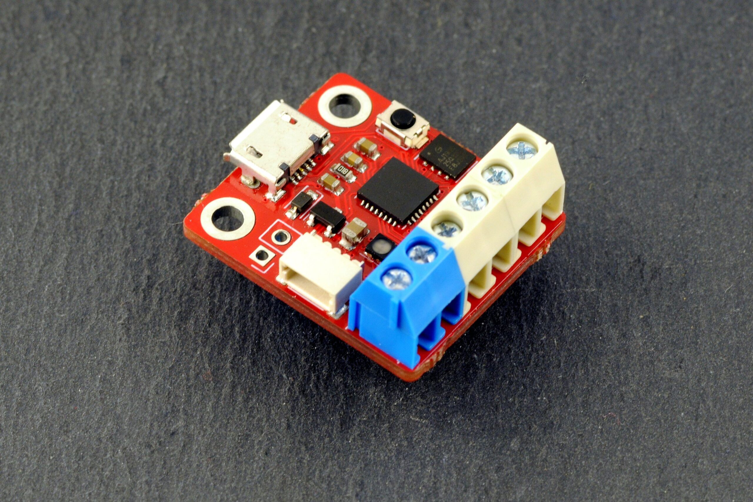
As Adafruit’s CircuitPython becomes increasingly popular as one of the basics for rapid microcontroller-based prototyping and development, several development boards are beginning to show up on the makers’ space to help fast track project prototype and production. One of such is the recent open-source CircuitPython development board by Omzlo called FIDI.

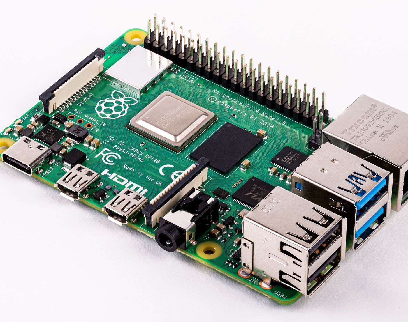
“FIDI is a small development board running Adafruit’s CircuitPython, featuring 6 terminal block connectors and a qwiic connector, designed for fast prototyping. It runs on the ATSAMD21 microcontroller, a 32-it ARM Cortex M0+ clocked at 480 MHz, as found on many popular Arduino-compatible boards”, says the open-source hardware designer.

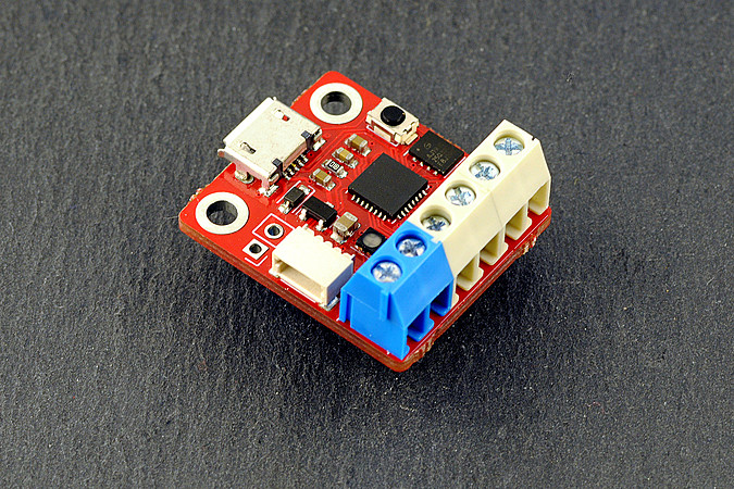
The tiny FIDI board is a derivative of the earlier released SERPENTE by Arthuro182, also aimed at rapid prototyping and producing quick projects. The two boards have quite a number of features in common but FIDI features 3.5mm terminal blocks, JST connectors, and a Micro USB connector that enhances its connectivity. FIDI is however fully compatible with the SERPENTE, even though there is no affiliation between the two designers.

The board measures 25.4mm by 22mm (about 1 x 0.86 inch) and has other technical features which include:

  • ATSAMD21E18A 32-bit Arm Cortex M0+ running at 48 MHz, fast enough for prototyping and simple applications.
  • 256 KB flash memory and 32KB RAM
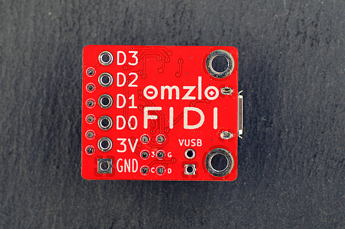
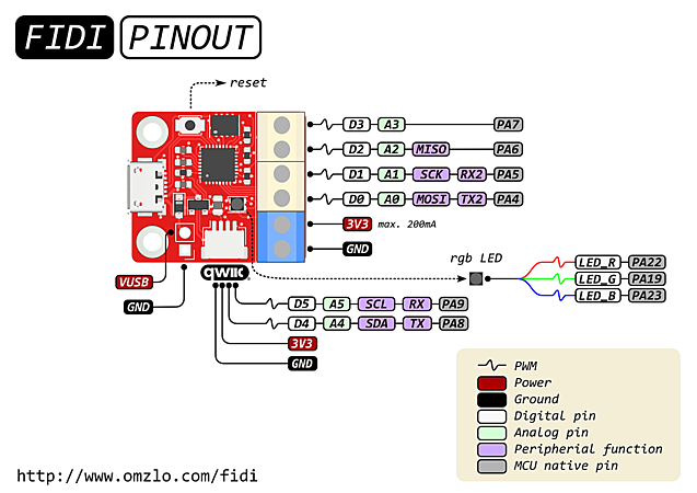
  • 6x highly customizable GPIOs, that can be configured as 12C, SPI, UART, PWM, analog and digital I/O or a combination thereof
  • Micro USB connection to PC
  • RGB LED (user-controlled)
  • 3.3V logic level and power
  • An LDO that provides a maximum of 200mA of current
  • One 4-pin JST-SH quick connector and,
  • Six 3.5mm terminal block connectors

Asides from the 3 terminal blocks to be soldered to the board (which can be done for you before shipping for a fee), the FIDI development board comes fully assembled and preloaded with CircuitPython 5.0.0, that helps you get started immediately.

“With CircuitPython, writing code for FIDI is super simple. Once connected to a computer with a simple USB micro connector, FIDI shows up as a USB drive where you can drag and drop or edit your python code.” Omzlo added.

The board also has a 4MB of additional flash for storing CircuitPython codes and other files. More details on the board including schematics and Kicad design files can be found on Omzlo’s official website or Tindle where the board sells for $15.

TinyUPS – Uninterruptible Power Supply based on ATtiny13A

Power interruption has a lot of side effects on projects. Especially projects with heavy processing requirements, it could corrupt the memory of the microprocessor/microcontroller, or lead to significant damage to other parts of the device. To mitigate this, several UPS solutions have been built, especially by folks in the Raspberry Pi community and as a contribution to this efforts, Wagiminator recently shared his designs for a UPS which is called TinyUPS.

TinyUPS is a simple 5V/2.5A uninterruptible power supply with a li-ion battery as a buffer, a load sharing power path management system, and an ATtiny13 which; monitors the power supply for availability, the battery level for charge control, and shares battery information and power status with the device being powered. The device performs the basic functionality of keeping your device, alive for a when external power supply abruptly fails.

The operation principle of the tinyUPS is quite straight forward. When an external power supply is connected to the tiny ups, the input voltage or VCC of the ATtiny13 is delivered to the device and when the external power supply is not available, the load is supplied by the battery. As the battery begins to run out, monitored by the ATtiny13, it tells the device it is time to shut down by pulling a pin dedicated as a shutdown pin, LOW. The developer of the device being powered is expected to read this pin from time to time and initiate the shutdown process for the device when the pin goes LOW. After pulling the shutdown pin LOW, the tinyUPS waits for a few minutes (SHUTDOWN TIMER) to allow the connected device to safely shut down, after which the ATtiny13 deactivates the boost converter and turns off the power to the connected device. If the input voltage rises again (as a result of external power source being available),  above a certain threshold (POWERONLEVEL) voltage, the tinyUPS comes on, activates the boost converter, and turns on power to the connected device.

The UPS has been tested for various performance indicators including power efficiency and the results as documented by Wagiminator are stellar. Few requirements by the device for top performance however include that the external power supply to be used be capable of delivering enough power to charge the battery and to power the device connected to the UPS simultaneously. The maximum battery charging current is set to 1000mA but you can set a lower limit by selecting a different value of R3. The output voltage of the external power supply must not exceed 5.2V!  and selecting a good 18650 with low internal resistance would be of high advantage.

A summary of some of the device’s power specification is provided below.

Parameter Value
Input Voltage 4.5 – 5.2 V
Output Voltage 4.8 – 5.2 V
Output Current Max 2.5 A
Charging Current Max 1000 mA
Standby Current 95 uA

Wagiminator has been kind enough to make the entire project open source, and all files from firmware to schematics and PCB layout are available on the project’s Github page. The page also contains a readme file that gives a broader explanation into the features embedded into the device.

Opto Diode Introduces AXUV20HS1 Circular Photodetectors That Detect Electrons to 200 eV

Opto Diode Corporation, an ITW company, introduces a high-speed photodetector with a circular active area of 5 mm diameter (typically 20 mm²). It is ideal for high-speed detection of low-energy electrons or X-rays. The AXUV20HS1 is one of several AXUV detectors that feature high performance measurement of photons, electrons, or X-rays.

The device features electron detection to 200 eV. The high-speed detector has a typical rise time of 3.5 nanoseconds.

Storage and operating temperatures range from -10 °C to +40 °C (ambient) and from -20 °C to +80 °C in nitrogen or vacuum environments. The lead soldering temperature is 260 °C. Opto Diode’s high-speed photodiode is shipped with a protective cover plate to safeguard the photodiode chip and wire bonds.

To view the responsivity graphs for the AXUV20HS1 photodiodes, please go to Opto Diode’s data sheet here: https://optodiode.com/pdf/AXUV20HS1DS.pdf.

To learn more about Opto Diode’s AXUV family of detectors that detect energy from 100eV to 50keV for the measurement of photons, electrons, or X-rays from 0.0124 nm to 190 nm, please contact sales@optodiode.com or visit: https://optodiode.com/photodiodes-axuv-detectors.html.

New SXUV5 Extreme Ultraviolet Photodetector Comes with Circular Active Area of 2.5 mm. Diameter

Opto Diode Corporation, an ITW company, introduces the SXUV5, an extreme ultraviolet (EUV) photodiode with a circular active area of 2.5 mm diameter. The new device has superior responsivity in the 1 nm to 190 nm wavelength region and is specially designed to be highly stable over long periods of time when exposed to high-intensity EUV energy. The new photodetector joins Opto Diode’s family of SXUV photodiodes with varying active area sizes to meet critical measurements, speed, and power monitoring performance objectives.

The SXUV5 is housed in a windowless, TO-5 package to allow for responsivity at wavelengths shorter than 150 nm. Other features include shunt resistance of 20 MOhms (minimum) and reverse breakdown voltage of 5 Volts (minimum) to 20 Volts (typical). Capacitance is 500 pF (typical) to 1500 pF (maximum), and response time is from 1 nsec (typical) to 2 nsec (maximum).

Storage and operating temperatures range from -10 °C to +40 °C (ambient) and from -20 °C to +80 °C in nitrogen or vacuum environments. The lead soldering temperature is 260 °C.

For additional information and to view the responsivity graphs for the SXUV5 EUV photodetectors, please go to Opto Diode’s datasheet here: https://optodiode.com/pdf/SXUV5DS.pdf.

Web Site: www.optodiode.com

Sub-miniature Rubidium oscillator offers 1,000x better stability

As demand grows, precision and reliability in Global Navigation Satellite Systems (GNSS) is critical. With 5G networks on the rise, small, high-performing atomic clocks are becoming increasingly essential. Suntsu’s newest oscillator comes in a dimension of 50.8mm x 50.8mm that uses an all new physics package enabling unprecedented miniaturization in a rubidium clock. Perfect support for applications in military communication equipment, base stations, test equipment, synthesizers, and digital switching.

This miniature oscillator, the SRO10S-10.000M, delivers a frequency accuracy of ±5E10-11 regardless of temperature fluctuations when the supply voltage ranges from 12VDC to 18VDC. Its power consumption maxes out at 6 Watts and has faster warm-up times at a variety of temperatures. These parameters are ideal for applications that require high performance, low power consumption, and small package sizes.

Specs include:

  • Frequency at 10MHz
  • Sub-miniature size of 50.8mm x 50.8mm
  • Frequency accuracy of ±05ppb
  • Aging per day of ±005ppb
  • Supply voltage ranges between 12VDC – 18VDC
  • Operating temperature between -30°C to 60°C
  • Sinewave output
  • MTBF of 100,000 hours
  • Dip type

more information: suntsu.com

STTS22H – Low-voltage, ultra-low-power, 0.5 °C accuracy I2C/SMBus 3.0 temperature sensor

The STTS22H is an ultra-low-power, high accuracy, digital temperature sensor offering high performance over the entire operating temperature range.

The STTS22H is a band gap temperature sensor coupled with an A/D converter, signal processing logic and an I²C/SMBus 3.0 interface all in a single ASIC.

This sensor is housed in a small 2 x 2 x 0.50 mm 6-lead UDFN package with exposed pad down for a better temperature match with the surrounding environment.

The STTS22H is factory calibrated and requires no additional calibration efforts on the customer side.

Features

  • Key features
    • Integrated high-accuracy temperature sensor
    • Factory calibrated
    • One-shot mode for power saving
  • Electrical specifications
    • Supply voltage: 1.5 to 3.6 V
    • I²C, SMBus 3.0 with ALERT (ARA) support
    • Programmable thresholds with interrupt pin
    • Supports up to 1 MHz serial clock
    • Up to 2 I²C/SMBus slave addresses
    • Ultra-low current: 1.75 µA in one-shot mode
  • Sensing specifications
    • Operating temperature -40 °C to +125 °C
    • Temperature accuracy (max.): ± 0.5 °C (-10 °C to +60 °C)
    • 16-bit temperature data output
  • Package specifications
    • UDFN 2.0 x 2.0 x 0.50 mm, 6 leads with exposed pad down
    • ECOPACK, RoHS and “Green” compliant

more information: www.st.com

BPW34 Gamma Ray Detector

The usual approach to radiation detection is the use of a Geiger-Müller tube and its high voltage circuit requirements, but during a quick surf through the internet today, I came across this portable and “accurate looking” solution developed by Stefan Wagner, on EasyEDA.

Rather than the Geiger Muller tube and its complex circuitry, the project uses a miniature Silicon PIN Photodiode, the 3x BPW34 (which were connected in parallel to improve sensitivity), as the primary sensing component. The BPW34 is a PIN photodiode with high speed and high radiant sensitivity in miniature, flat, top view, clear plastic package. It is sensitive to visible and near-infrared radiation and has a small sensitive area, which is an advantage in radiation detection, as the background rate due to cosmic rays is very low, and signals from small samples will be easier to detect than when a counter tube is used.

The behavior of the BPW34 PIN photodiode used in the project is similar to that of a low-cost counter tube in the sense that, while alpha particles may be stopped by the enclosure of the device, gamma rays due to their high penetration ability will pass through and create electron-hole pairs in the depletion layer of the diode. This will lead to the charge carriers in the diode being drawn away and a small current pulse being created. The small current pulse can then be amplified and processed to determine radiation levels.

For the amplification, the project featured an instrumentation amplifier and the processing is done with an LM3111 operation amplifier which is used to compare the values and trigger a buzzer when radiation is detected.

With the Geiger-Muller tube becoming hard to find and the high voltage circuitry adding another layer of complexity, this accurate approach by Stefan using relatively, readily available components might be the best way to build your next radiation detection device.

The project notes the interference of light during measurement and suggested that the BPW34s be covered with thin aluminium foil.

The project is entirely open source and the schematics, PCB design file, BOM, and other files are available on the project’s page on EasyEDA.

Meet the Breadboard Compatible MCP4901 DAC Based Breakout Board

US-based technology Product development company, Earth People Technology, recently announced the launch of a DAC (digital to analog converter) breakout board that is based on the popular eight-bit MCP4901 DAC Chip.

The new breakout board, in line with the nature of the products developed by the company, comes with breadboard compatibility which makes it easy to use for prototyping and DIY applications. Speaking on the features, the company announcement mentioned that the board was designed to suit applications involving development boards like the Arduino family of boards. In their words –

“This DAC board features the MCP4091 eight-bit Digital to Analog chip. It is designed to fit into a breadboard and connect to an Arduino board.”

The MCP4091 DAC on which the board is based generates analog voltages from the ground to its voltage reference (VREF) — which can be adjusted to a value between the applied VCC and ground using an on-board potentiometer. The DAC takes digital inputs and converts them to an analog value between 0-255 with 0 being ground and 255 being VREF.

Describing the features of the breakout board, the announcement mentioned that –

“The device includes double-buffered registers, allowing synchronous updates of the DAC output using the LDAC pin,” and also “incorporate a Power-on Reset (POR) circuit to ensure reliable power-up”.  It also features “a resistive string architecture, with its inherent advantages of low Differential Non-Linearity (DNL) error and fast settling time”, and ” is specified over the extended temperature range (+125°C).”

The breakout board which was given the model name “EPT-4901-DA-s1”, operates on a single rail supply of between 2.7v – 5,5v, as such could be reliably powered from a 3.3 or 5v voltage supply. It communicates with a microcontroller via an SPI (Serial Peripheral Interface) interface which reduces wiring and also makes it easy for both the DAC and the MCU to isolate themselves in such a way that the signal at the input of the ADC is not affected by interference/noise from the microcontroller.

To enable DIY enthusiasts and prototyping engineers to get up to speed, out of the box, the board comes with sample Arduino sketches that show how users can send a digital value to the board, and produce a voltage output.

More information on features and specifications of the board can be found on the recently released datasheet, and it can be bought from Earth People Technology’s Tindie store, for $6.99.

STMicroelectronics Expands Portfolio of FlightSense ToF Ranging Sensors

STMicroelectronics announced the release of the VL53L3CX, a capability expansion of the company’s FlightSense ToF ranging sensors, with a patented histogram algorithm.

The new sensor measures object ranges from 2.5cm to 3m, remaining unaffected by color or reflectance.

The histogram algorithm increases cover-glass crosstalk immunity and allow real-time smudge compensation preventing external contamination from adversely affecting the ranging accuracy for a number of applications.

Further, the VL53L3CX has increased linearity, increasing short-distance measurement accuracy. This enhances wall tracking, cliff detection, and obstacle avoidance in equipment.

ToF sensing help to heighten the performance of application by allowing for more accurate occupancy detection in building-automation and lighting controllers, smarter proximity sensing in IoT endpoints, more convenient auto-wakeup in portable devices, and more robust user detection in automatic sanitary equipment.

For more information please go to www.st.com/vl53l3cx-pr

Raspberry Pi 4 Beta Firmware Brings True USB Boot for High-Speed Storage – no SD Card needed

One important feature of the Pi 3 flavor of the Raspberry Pi is the ability of the Pi to boot from a network server or a USB Mass storage device, rather than the, pretty much standard way of booting from an SD Card. However, while the Pi 4 featured several upgrades both physically and “OS-lly”, it did not have the USB external device boot ability which users have come to love. To profer a solution to this, the Raspberry Pi team has been working on a firmware fix, and they recently announced its readiness for a beta-testing.

The new firmware, when complete, will give users the ability to boot the Pi from Network server or a USB Mass Storage device, giving the owners of the Pi 4 the opportunity to connect the Pi, through its high-speed USB3.0 ports, to a USB 3.0 storage device as their operating system installation point.

Since a few weeks after launch, the network boot functionality had been reinstated via a firmware update, but the USB boot functionality was still not available, and while methods like the addition of a boot stub on a microSD, help load the OS from USB, they were not exactly elegant solutions.

The USB boot functionality has now been reinstated in the latest update and the foundation is now calling on users who are interested in serving as beta testers to help test it before it is made available to the general public.

The update is currently available as a public beta, and the instructions for upgrading to the beta firmware, configuring the bootloader on your Pi, and reporting discovered bugs, can be found on the Raspberry Pi website and this detailed forum thread.

One of the goals of Pi 4 is to have it serve as a standalone computer, and the USB Boot functionality might be key to that as it allows users to run the Pi from a USB Storage device without the need for a Micro SD Card.

TOP PCB Companies