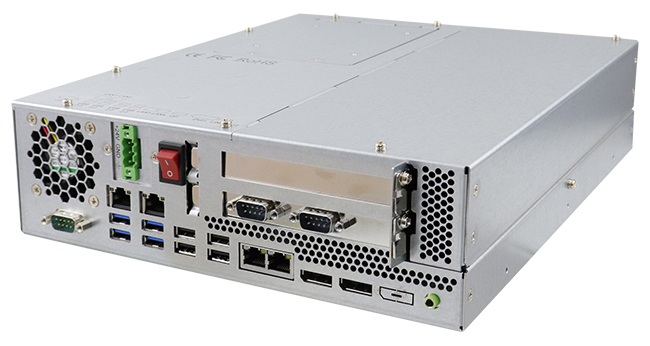
IBASE Technology Inc., a leading provider of industrial motherboard and rugged computing solutions, is pleased to announce its AMS210 high-performance embedded box PC. Designed for factory automation, machine vision, digital signage and a wide range of industrial IoT applications, the AMS210 can be outfitted with 9th/8th Gen Intel® Core™ processors, up to 32GB of DDR4 memory and two 2.5” disk drives with RAID 0/1.
The AMS210 has a straightforward design with front I/O accessibility, including four USB 3.1, four USB 2.0, three DisplayPorts, and a serial port to connect to a diverse set of peripheral devices, as well as four Gigabit LAN ports to handle high bandwidth data processing requirements. Two flexible expansion slots supporting a combination of PCI-E(x16), PCI-E(x4) and PCI interface are also conveniently located at the front for easy access. To achieve operational reliability in harsh industrial environments, it features an operating temperature range from 0°C to 55°C and vibration endurance of up to 3 Grms (with SSD).
Measuring 297.4(W) x 266.2(D) x 78.5(H) mm, the AMS210 is available in barebone or can be equipped with an Intel® Core™ i7-9700TE processor, 8GB RAM, and a 500GB SATA drive. It also supports an optional 24V power adaptor and two additional serial ports. For more information, please visit www.ibase.com.tw
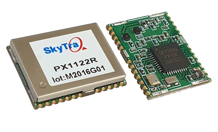
SkyTraq announced a 12- x 16-mm size PX1122R multi-band RTK receiver for centimeter-level accuracy GNSS positioning applications.
The receiver works with all the four global navigation satellite systems using GPS L1/L2C, Galileo E1/E5b, GLONASS L1/L2, and Beidou B1I/B2I signals concurrently to maximize positioning availability even in difficult urban environments. Based on single-chip SoC design, PX1122R is currently the smallest size, lowest power, multi-band multi-GNSS RTK receiver module on the market.
The PX1122R is designed to deliver reliable, centimeter-level accuracy positioning for precision guidance of emerging autonomous unmanned ground or aerial vehicle, Internet-of-Things precise positioning, and also the traditional land surveying and precision farming applications. The PX1122R has RTK initialization time under 10 seconds and maximum update rate of 10 Hz. Its twice update rate than peer provides in-time positioning information with faster response time and improved guidance performance for fast moving applications.
Moving base RTK for GNSS precise heading is also supported. By using two PX1122R and two antennas with 1 meter separation, highly accurate 1-sigma heading accuracy of 0.13 degree can be obtained; such heading accuracy is immune to magnetic interference nor affected by receiver’s speed.
The PX1122R could serve as a key component to provide precise position and heading information for autonomous applications. PX1122R sample, datasheet, and evaluation boards are available now.
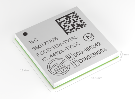
Murata Electronics today announced that their LTE-M solution powered by Altair Semiconductor’s advanced cellular chipset has secured Deutsche Telekom certification for operating on the carrier’s German 4G LTE wireless network. Measuring just 11.1 x 11.4 x 1.4 mm, the module is the world’s smallest form factor solution and enables applications to move the market forward, such as mobile IoT. In addition to its unparalleled size, low power, and cost efficiency, the Type 1SC’s high level of integration drastically cuts time to market and reduces customers’ certification costs.
The module contains Altair’s advanced cellular IoT chipset; the ALT1250 (https://altair-semi.com/products/alt1250/). With an industry-leading low power consumption, it enables IoT devices to run for longer, providing years of operation without the need to replace batteries. Commercially available, the RoHS-compliant chipset features a hardware-based security framework and a rich set of features including integrated SIM (iSIM), an ARM Cortex M4 MCU for the user’s IoT applications and GNSS, ideal for enabling a wide-range of industrial and consumer IoT applications.
Flexible and optimized solutions are the building blocks for realizing IoT on every wireless device. The Type 1SC is the first LTE-M module to be certified by Deutsche Telekom for use on its network. Developers can now leverage the Type 1SC’s confirmed interoperability with the mobile operator’s network to introduce new products and services.
“With the Deutsche Telekom certification, mutual customers can easily tap Murata’s RF expertise and access best-in-class solutions,” said Koichi Sorada, Product Manager Connectivity Modules, Murata Europe.
“Murata is a leading provider of innovative building blocks for the Internet of Things and through our strong partnership we continue to secure superior performance and quality needed for success in mobile IoT,” said Wayne Gilbert, Head of IoT Device Integration and Validation at Deutsche Telekom.
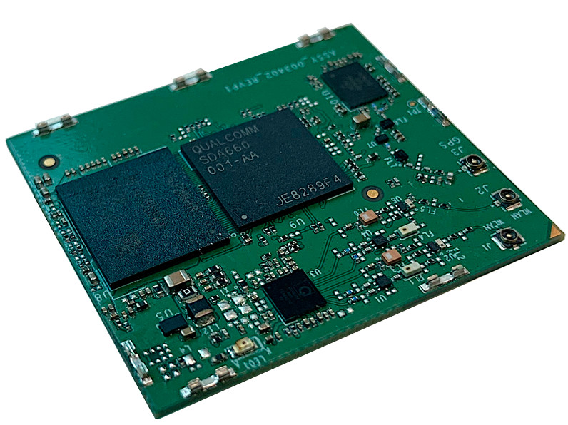
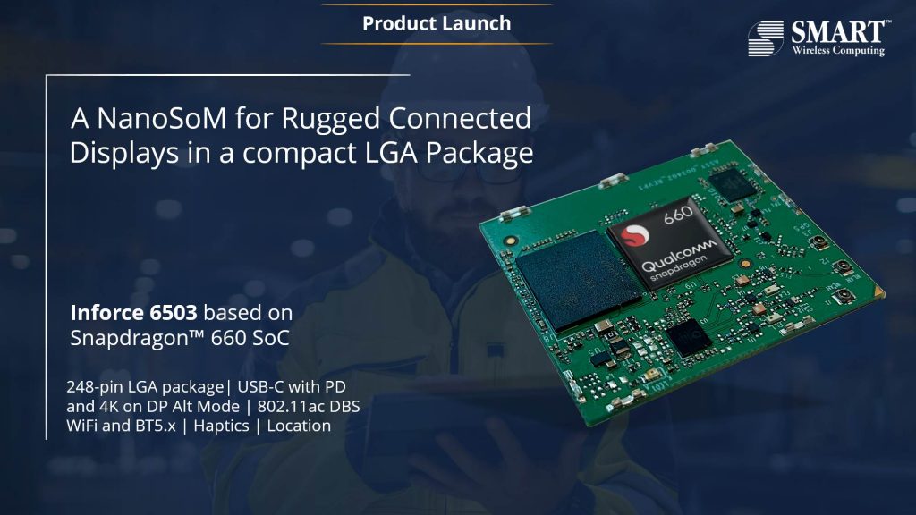
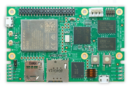
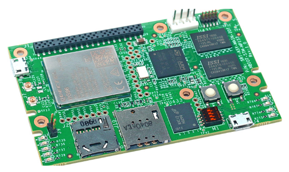
SMART Wireless Computing® (part of SMART Global Holdings), a leading provider of Snapdragon™ embedded computing platforms and solutions, today announced a compact compute module in an LGA package, Inforce 6503. Inforce 6503 enables advanced visual computing, enhanced graphics, and on-device machine learning capabilities featuring the Qualcomm® Snapdragon™ 660 processor.
The Inforce 6503 SoM powered by the Snapdragon 660 Octacore processor brings true-to-life colors and lifelike visuals coupled with AI-enabled user experiences. This computes module combines the heterogeneous computing capabilities of the Snapdragon™ SoCs with 2×2 802.11ac Wi-Fi with DBS, Bluetooth5.x, haptics, a full-featured USB-C interface with UltraHD display capability and ample internal memory to make it a complete 4K encode/decode systems. With support for dual MIPI-CSI cameras, depth perception use-cases like proximity detection, semantic segmentation, autonomous driving, and facial recognition can be enabled with ease on systems built on these SoMs.
The SoM comes in an ultra-small form factor of 40mm x 35mm in an LGA package and is light-weight. It is a perfect fit for rugged applications that requires sturdy mechanical fitment and a need for low vertical profiles. Target end-uses that can benefit from these capabilities include rugged connected displays, high-end industrial IoT, wearables, portable healthcare with advanced imaging requirements, and connected cameras’ domains. Optional SKUs support extended operating temperature range and EMI shielding for better RF noise protection, while also doubling up as a medium for heat spreading and dissipation to further improve performance. SMART wireless offers a reference carrier board design with this SoM to help create and optimize your products with the shortest turnaround time.
An Android BSP releases package comes pre-loaded on these products from SMART Wireless with committed periodic upgrades supporting all available peripherals.
“Our customers are engineering the Internet of Everything. SMART Wireless is dedicated to delivering sophisticated embedded solutions and these new SoMs are a perfect fit for our product roadmap.” said Jagat Acharya, VP at SMART Wireless Computing, Inc. “Qualcomm Technologies has delivered new innovative architectures that drive machine learning, Artificial Intelligence and Immersion in the Snapdragon 660 processor. Our experience in combining these with home-grown efficient software solutions coupled with support products help product makers to rapidly access the capabilities they need to create powerful, connected solutions.”
SMART Wireless offers long-life supply commitment and lifecycle assurance, support for hardware customization, and custom software. With extensive design and manufacturing experience, SMART Wireless creates shippable products that can pass FCC Class A/Class B, CE including RED 2014/35/EU and all regulatory compliances applicable in multiple countries across the world.
More information about the new product can be found in Smart Wireless Computing’s announcement and product page.
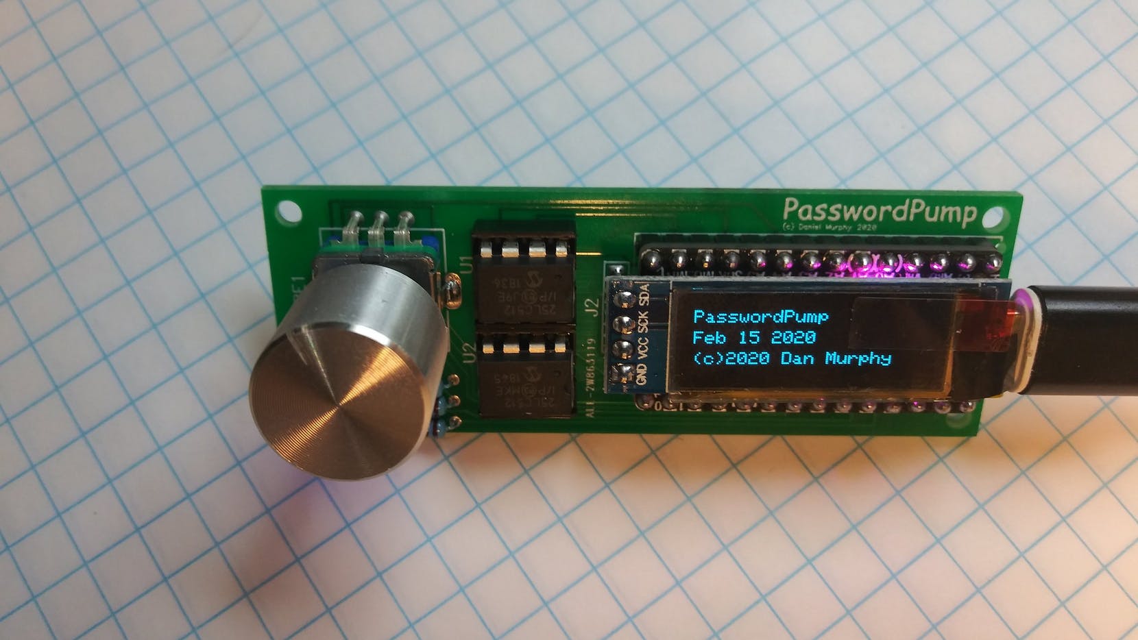
Using the same password on different platforms can be a security risk, but remembering different passwords, used for different accounts, can be quite the task too especially with the need to infuse special characters and numbers, and the fact that you may not use some of the passwords regularly enough for them to become easy to remember. To help keep track of all these, Dan Murphy has designed a USB- based device that is capable of storing up to 250 sets of credentials, that are encrypted with AES-256 encryption, which makes gaining access to the credentials nearly impossible.
The new device called, PasswordPump 2.0, removes the need to store your credentials in the cloud or on a file where an attack could easily leave you exposed.
It is based on the Adafruit ItsyBitsy M4 and includes; a pair of removable EEPROM chips, an I2C OLED display (128 x 32), and a rotary encoder, all stacked on a custom PCB. The credentials are stored on the first EEPROM chip and backed up on the secondary for added security.
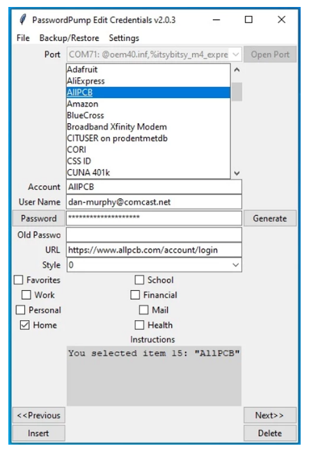
The device allows users to enter their credentials using several methods, including; the rotary encoder, the keyboard, via the serial terminal, or via the PasswordPump Python-based GUI, which was explicitly developed for this purpose.
PasswordPump Python-based GUI
The PasswordPump 2.0 offers a myriad of features, which are as provided by Murphy:
Store up to 250 sets of credentials
Authenticate with a 15 character master password
Search for accounts
Data entry via rotary encoder or keyboard and serial monitor, or via client Python GUI running in Windows, Ubuntu, or MacOS.
Send username and password as if typed in via keyboard. Can also send URL, old password and account name.
Add account name, username, password (generated or not), URL, old password
Accounts added in alphabetical order
Edit existing username, password, URL, style (inter-username/password character, Return or Tab), old password
Automatically saves old password if it’s not already populated
Delete account
Generate 31 characters’ random password from the PasswordPump or via the client GUI.
Backup all accounts to a second encrypted external EEprom
Logout / de-authenticate via the menu, automatically locks the computer
Factory reset via menu (when authenticated) wipes out all credentials
Configurable automatic logout after a count of minutes (30, 60, 90, 120, 240, 1 or Never)
Configurable RGB LED intensity (high, medium, low or off)
All passwords (except the master password) are encrypted w/ AES-256; the master password is hashed w/ SHA-256.
All encrypted accounts and the hashed master password are salted
Change master password
Export to PasswordPump formatted CSV file
Import from PasswordPump formatted CSV file
Import credentials from Chrome export
Import credentials from KeePass export
Associate credentials with groups for better organization; search by group (Favorites, Work, Personal, Home, School, Financial, Mail or Custom)
Decoy password feature that automatically factory resets the device if entered (e.g. while the user is under duress)
Pre-auto-logout indicator/countdown via red and blue flashing RGB LED.
The device’s design is open source and a detailed guide on building the device with schematics, and code along with a complete BOM is available on Murphy’s Website. He also has the device for sale on Tindie for those who will rather just buy it. It goes for $35 plus $10 for shipping.
Murata has introduced the SCC300 series components that combine high-performance angular rate and accelerometer sensor components. The SCC300 is the 3rd generation of MEMS (Micro-Electro-Mechanical Systems) 4DoF (four-degrees-of-freedom) and 5DoF (five-degrees-of-freedom) inertial sensors that realize high-performance for safety-critical automotive applications. The new device consists of versions of an X-axis, Z-axis, and XZ-axis angular rate sensor and a 3-axis accelerometer sensor.
The SCC300 series is designed, manufactured, and tested to deliver reliability, quality, and extremely stable output over a wide range of temperature, humidity, and vibration conditions. The sensor in the device is designed to meet the new shock and vibration requirements coming from integrated brake systems for more cost-effective and size effective ESC (Electronic Stability Control) functionality in modern electrified vehicle architecture.
The SCC3000 series provides a cost-effective realization of ESC product family for both standard and high-specification ESC with additional features. Pin-to-Pin Compatability combined with common SPI-interface in the components to reduce the engineering effort at the system supplier level, this strengthens the system robustness.
Features of SCC300 Components
ISO26262 compliant for systems up to ASIL-D
Excellent bias stability, low noise level, and excellent vibration robustness
±300°/s angular rate measurement range for robust sensing in harsh environment
±6g acceleration measurement range
±15g auxiliary acceleration measurement range
-40°C~+110°C operating temperature range (Contact to Murata if +125°C is needed)
The new components are also designed with the features like extensive failsafe functions and error bits for diagnostics, they are also designed with internal reference signal monitoring, checksum techniques for verifying communication, and signal saturation/over-range detection. The continuously operating self-test function of the 3-axis accelerometer monitors the sensor during measurement. The self-test function in the device makes sure that the entire single chain from MEMS sensor movement to signal conditioning circuitry for every measurement-cycle is operating properly.
The SCC300 is suitable to be used in Electronic Stability Control (ESC) Headlight alignment, Roll Over and Roll Stability Control, Dynamic Chassis Contol, Lane Keeping Assistance (LKA), motion, and navigation measurement. To know more about the SCC3000 series X/Z-axis Gyro & 3-axis Accelerometer, visit the official website of Murata Manufacturing Co Ltd.
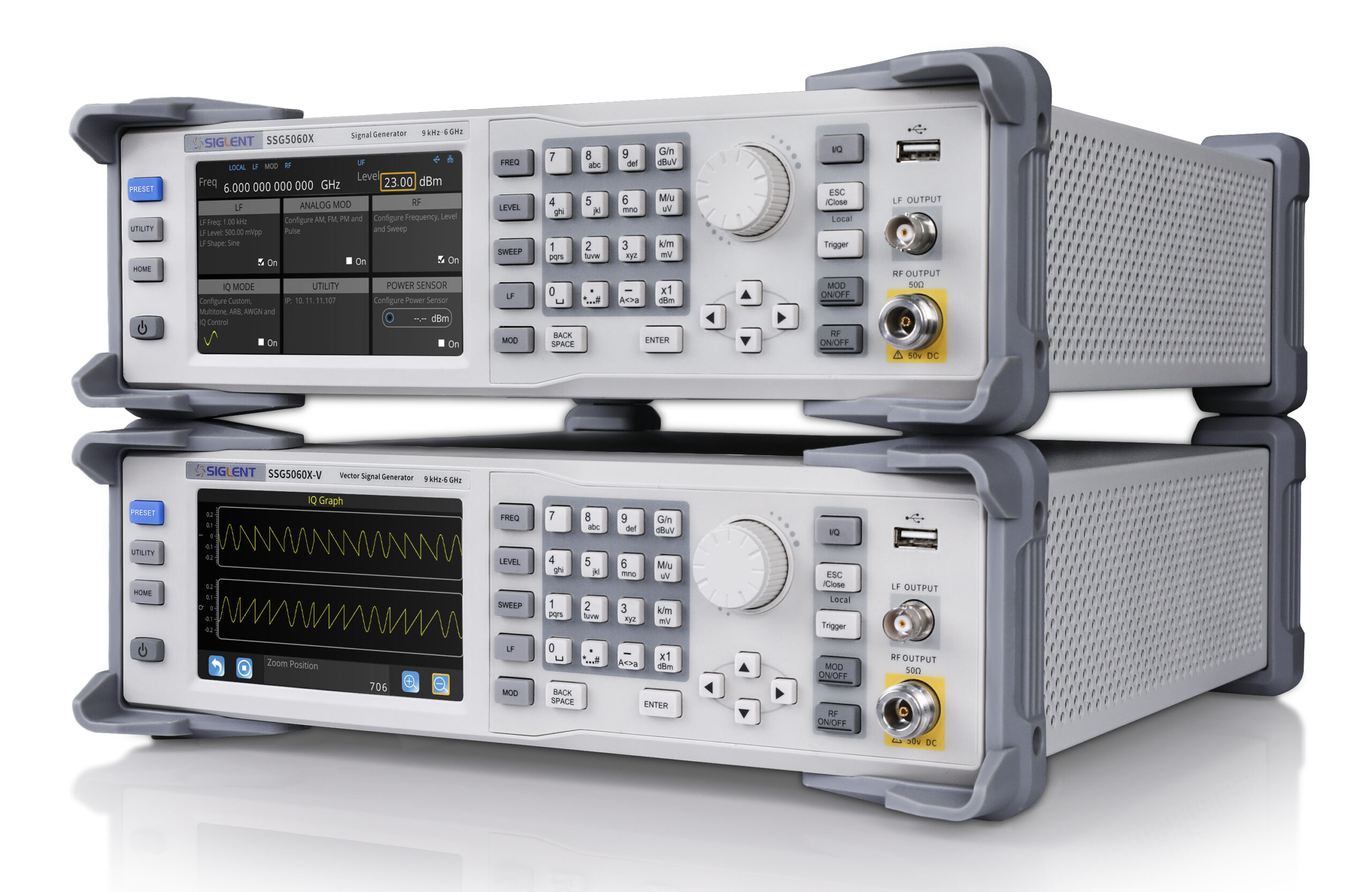
With powerful functions and wide frequency range, the SSG5000X vector signal generators offer excellent performance in phase noise, spectral purity, bandwidth, EVM, and output power, and suit a wide range of application fields
Saelig Company, Inc. has introduced the Siglent SSG5000X RF Signal Generators which generate analog and vector signals over a frequency range of 9kHz to 4GHz/6GHz with a 0.001Hz frequency setting resolution. They offer excellent performance in phase noise, spectral purity, bandwidth, EVM, and output power. The internal IQ modulation generator and waveform playback function on the –V models make it easy to create even the most complex signal types. They also cover the most important RF band for digital wireless communications and include standard waveform files.
The SSG5000X’s 5” color touch screen makes controlling the instrument fast and intuitive. It produces a maximum output power +26dBm (typ.) with phase noise of -120dBc/Hz @ 1GHz, 20kHz offset (typ.) The ARB Mode can be used to play back digital communication waveform files, while the Custom Mode on the –V versions can generate IQ modulated signals, such as QAM, PSK, ASK, FSK, sample rate up to 120Msps. Frequency sweeps can be performed in linear or logarithmic steps. AM, FM, PM analog modulation can be accomplished with internal, external, or Int+Ext sources. Built-in digital communication waveform files such as 5G-NR,LTE, WCDMA, WLAN, BlueTooth, and CDMA are also available. The SSG5000X can add real-time AWGN to modulation signals when testing receiver performance, or quickly simulate noisy RF environments. It supports multi-tone signal consisting of up to 20 sine wave frequencies. This is helpful for audio measurements, amplifier and receiver non-linear distortion tests, and ground and satellite communications tests.
Flatness correction is often needed to compensate for transmission line losses or switching impedances. The SSG5000X supports flatness correction with an external power sensor (not included) and is compatible with the most popular USB power sensors on the market. Standard interfaces include USB Host, USB Device (USB TMC), LAN (VXI-11, Socket, Telnet), GPIB (opt.) and PC control is available, even remotely via a web browser.
The SSG5000X RF signal generator series provides an engineer with an output library of the most common protocol signals and the flexibility to create custom formats to test the limits of new designs. With powerful functions and wide frequency range, SSG5000X generators are helpful in a wide range of application fields, such as receiver and amplifier testing, IP3 measurement, radar, digital modulation verification, spur and harmonics measurements, ACPR tests and cable loss compensation, for R&D test & measurement, education, or manufacturing test.
While the Arduino series of development boards have ease-of-use features that have made them a darling of the community, there are several situations where using them is not an advisable course of action for a project. Especially in projects where the developers desire a small form factor or the device is required to be low power. As a substitute, developers usually go with Atmeg328p MCU in most situations, but even this increases the size of the project by a significant amount. To solve all of this in recent times, designers turn their attention to a new ATtiny series of microcontrollers and for today’s project, we will focus on how the new series can be used with the Arduino.
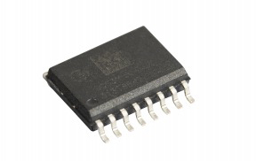
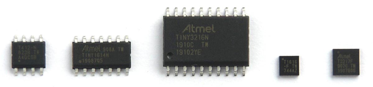
A selection of the new ATtiny chips: SOIC ATtiny412, ATTiny1614, and ATtiny3216; QFN ATtiny1616 and ATtiny3217. (image: technoblogy.com)
They may not be as popular as the Atmega328p microcontrollers, but the new ATtiny series of microprocessors from Microchip such as the ATtiny85 or ATtiny2313 needs no introduction. They power a range of tiny devices like the Digispark series of boards but are unfortunately almost useless in tasking applications as they have very limited Flash (usually less than 8K) and RAM (less than 1K). To improve on this, Microchip has released a new series of ATtiny chips with more memory and functionality, enough to go head-to-head with even some of the more expensive and popular Atmega series of chips.
While these chips had amazing features and capacity, they are plagued with two major downsides:
They come in SMD packages and are not breadboard compatible, making them difficult to use for DIY hobbyists
They lack the toolchains possessed by MCUs like the Atmega328p which allows their users to enjoy the same programming ease associated with Arduino boards (and clones).
To go around these downsides, engineers and DIY hobbyists, in no time, started creating different open source solutions that allow the chips to be programmed via the Arduino IDE. For today’s tutorial, we will create an adapter to make the chips breadboard friendly and also examine how someone can use open-source solutions to allow you to program the microcontrollers using the Arduino IDE.
Ready? lets go!
Required Components
The following components are required to build this project:
These components can be bought from your favorite online stores.
Building the ATtiny Adapter
As mentioned during the introduction, one of the biggest challenges using the new ATtiny series of microcontrollers is their SMD nature which makes prototyping difficult as the chip cannot be plugged directly into a breadboard. To remove this drawback, we will design an adapter for the chip.
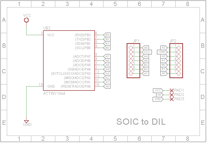
The schematics for the adaptor is a simple one. All we need to do is to route lines from the mounting pads of the ATtiny to header pins. However, this is implemented on a PCB since its the neatest way to implement anything involving SMD components. The adaptor was designed using Eagle CAD and the schematic is shown in the image below;
Adapter Schematics (credit: John Bradnam)
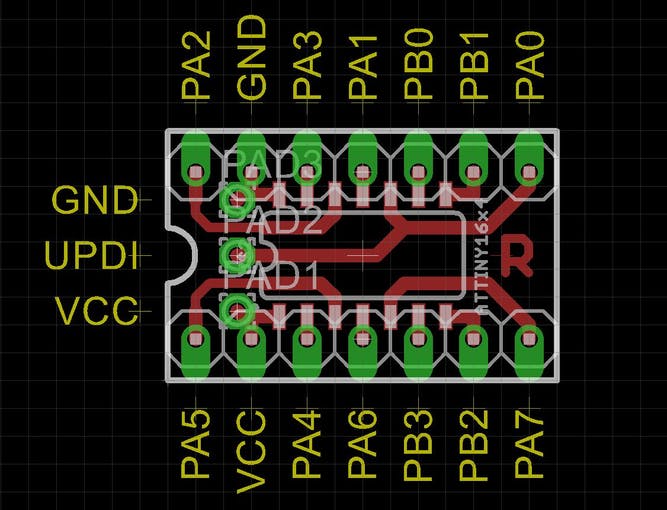
The PCB after the design is shown in the image below:
Adapter board for an ATtiny1614 (credit: John Bradnam)
As you’ve probably noticed, the DIL pin layout of the adaptor is different from the layout of the SMD microcontroller itself. This was done to keep the PCB, single-sided, and to also keep its width within 0.3in, as routing the PCB in such a way that the layout is the same as the SMD chip will require a wider or double-sided PCB. The 0.3in width of the adaptor was intentional, as it is the width required for the adapter to fit into a standard 14pin IC socket.
The breakout pins on the top part of the board, represent the UPDI/RESET, VCC and GND pins through which a programmer can be connected to program the microcontroller. Breaking these pins out at the top of the adaptor board makes it easy to program the ATtiny even when the adapter has been soldered into a project.
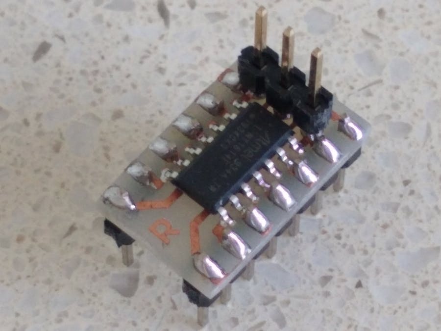
Adapter board with the ATtiny after soldering (credit: John Bradnam)
To make it easy for you to print your own PCB, all the Eagle CAD source files, including Gerbers, have been attached to the zip file under the download section. Feel free to either print directly or modify it to suit your needs.
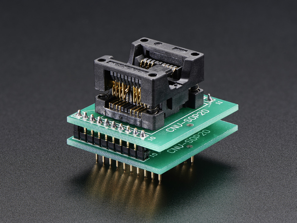
If you will, however, prefer a more flexible adapter that can be reused for multiple chips, without the need to solder and desolder the chips, you can go for this ZiF socket-like adapters on sale at adafruit.
SOIC to DIL on Adafruit
Schematics
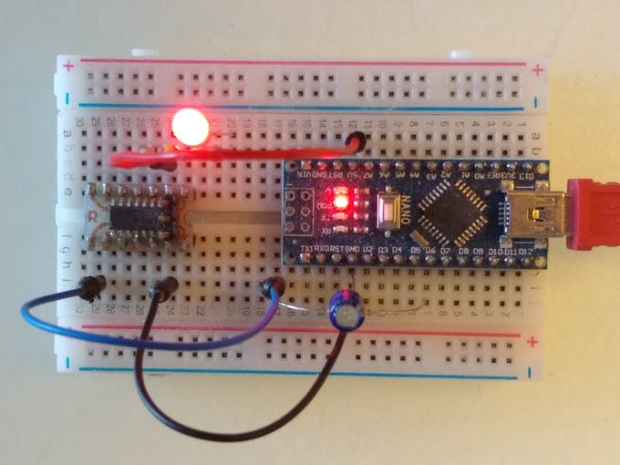
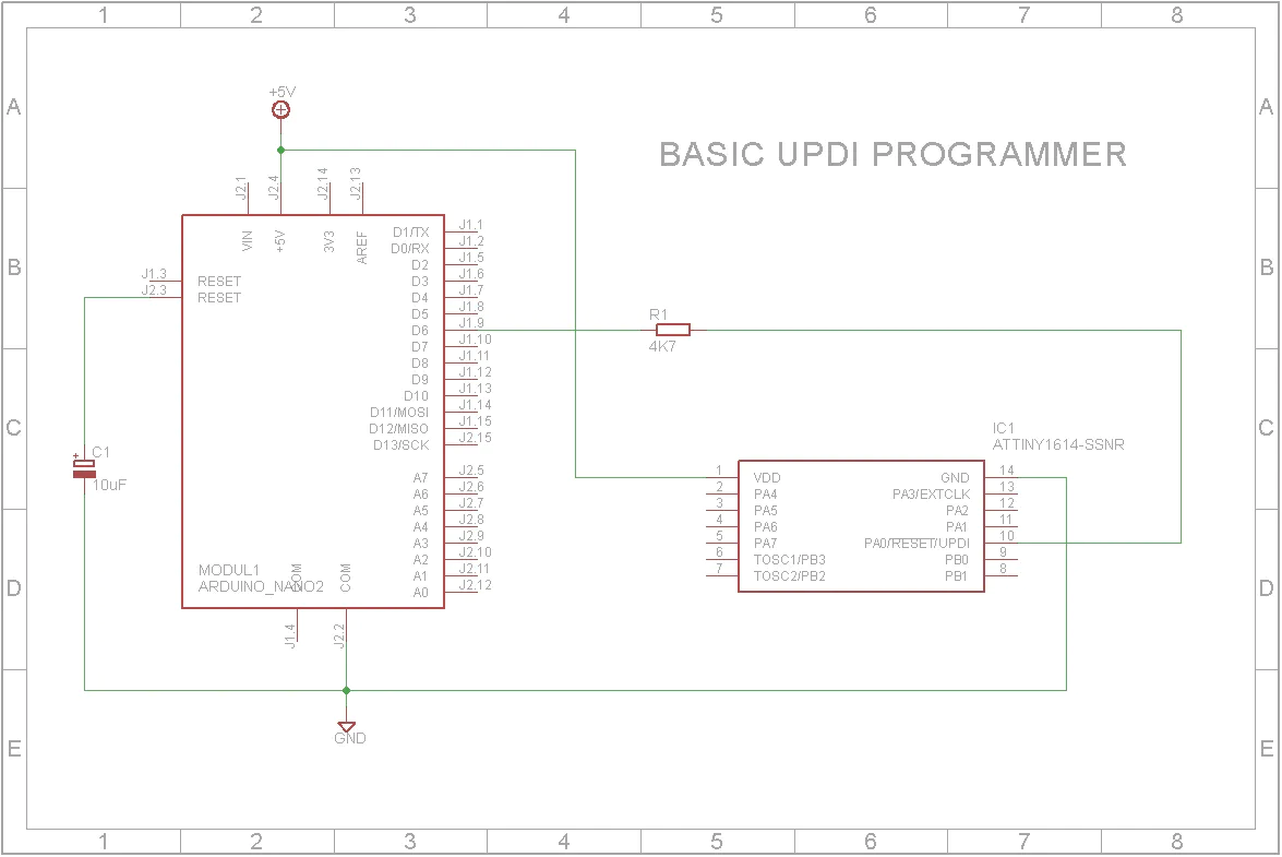
With the adapter in place, the next line of action is to connect it to a programmer which will, in turn, be connected to your computer. For today’s project, we will use an Arduino Nano as the programmer and the schematic below shows how the adapter is connected:
Connect ATtiny to Programmer (credit: John Bradnam)
To further highlight the connection, a pin map showing how the components are connected, pin-pin, is provided below:
Arduino – Adapter/ATtiny
GND - GND
5V - VCC
D6 - UPDI
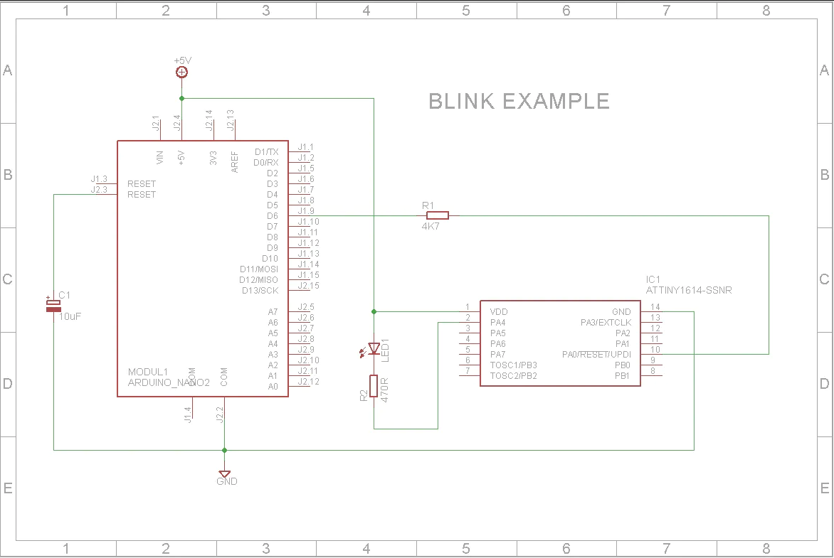
As a demo to show the ATtiny in action, we will implement the Arduino blink example. To do this, connect an LED to the setup as shown below:
Schematics (credit: John Bradnam)
With the programmer and LED connected, we can now proceed to examine the process of uploading code to the ATtiny.
Preparing the Arduino IDE
To bring the ease of programming with the Arduino IDE, which is experienced by the regular Arduino boards and clones, to the new ATtiny MCU series, Spence Conde developed a board package called the megaTinyCore which allows you to effortlessly program the latest series of ATtiny MCUs via the Arduino IDE.
The megaTinyCore requires Arduino IDE version 1.6.3 or later although it was stated on its GitHub page that it may require a much more recent version of the IDE with the initial tests done on version 1.8.9.
The megaTinyCore can be installed on the Arduino IDE in two ways:
Installation via the Arduino Board Manager
Manual Installation
I will explore both methods and let you decide which is easiest or faster.
1. Installation via the Arduino Board Manager
The Arduino board manager was designed to make the installation of new boards and add-ons easy for users. To install the megaTinyCore using this method, follow the steps enumerated below:
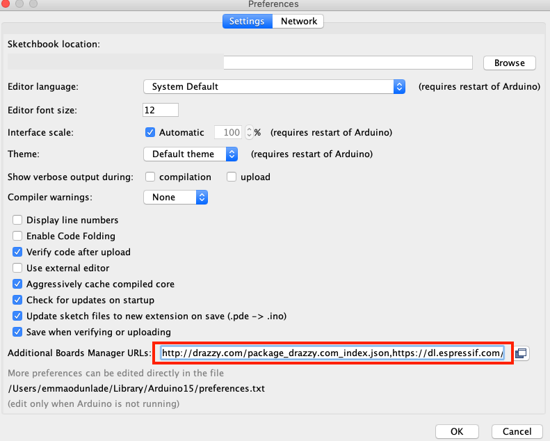
1. Open the preferences window from the Arduino IDE. Go to File > Preferences or Arduino > Preferences if working from a macOS
2. On the preferences window, locate the “Additional Board Manager URLs” text box and enter http://drazzy.com/package_drazzy.com_index.json into the field as shown below and click the OK button
Add the Link to Additional Board URL List
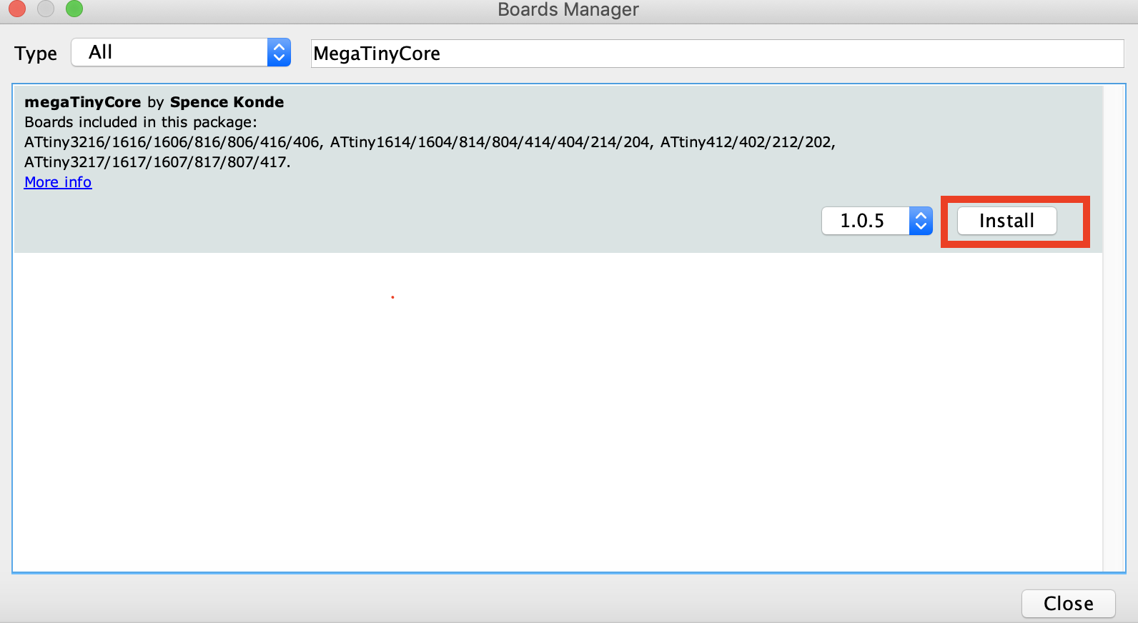
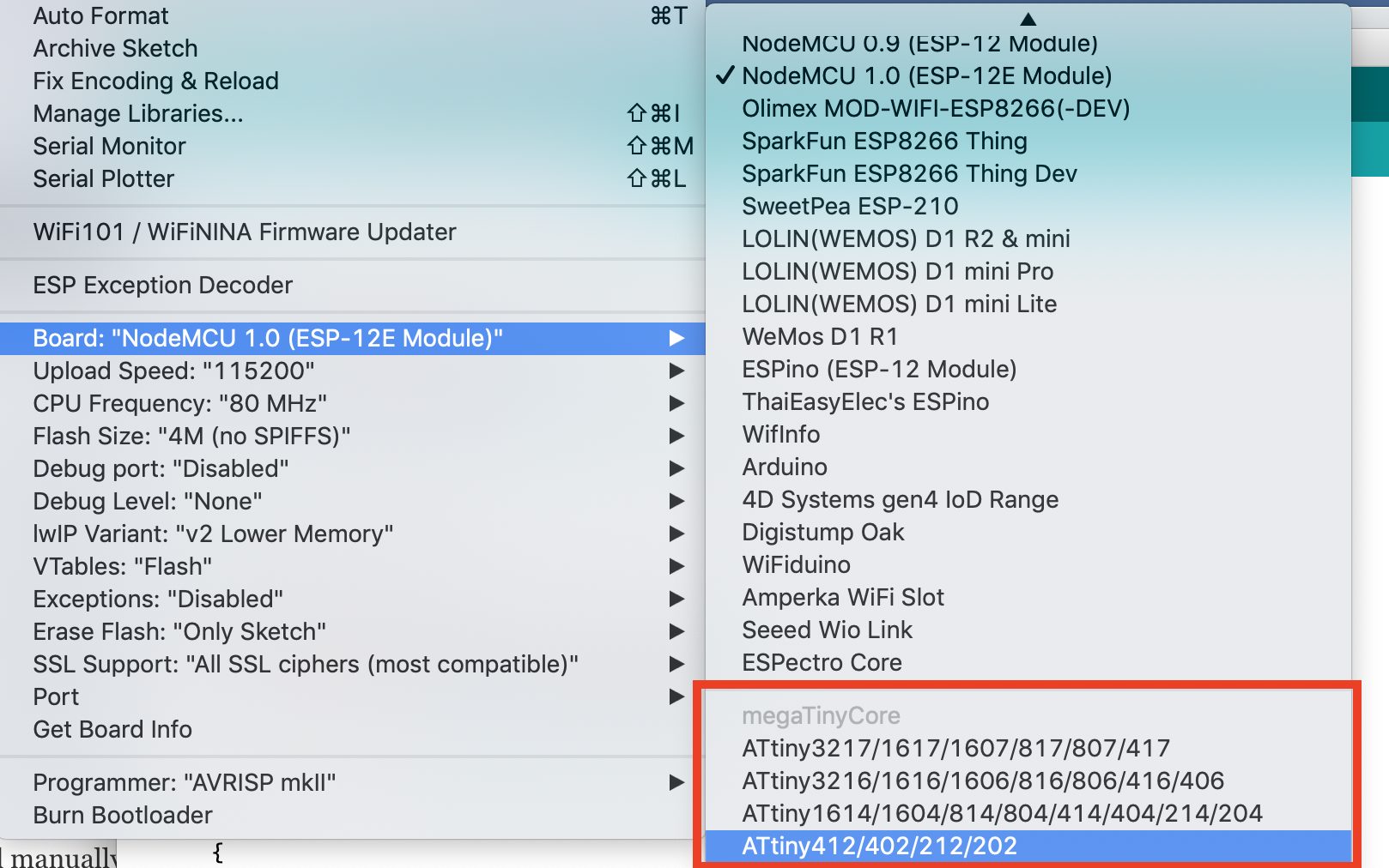
3. Next, open the Arduino board manager. Go to tools>Boards>Boards manager
4. When the board manager opens up, enter megaTinyCore into the search bar and scroll, you will see “megaTinyCore by Spence Konde”, click on install as shown below.
5. Also, search for the “Official Arduino megaAVR boards” package and install the most recent version of that too.
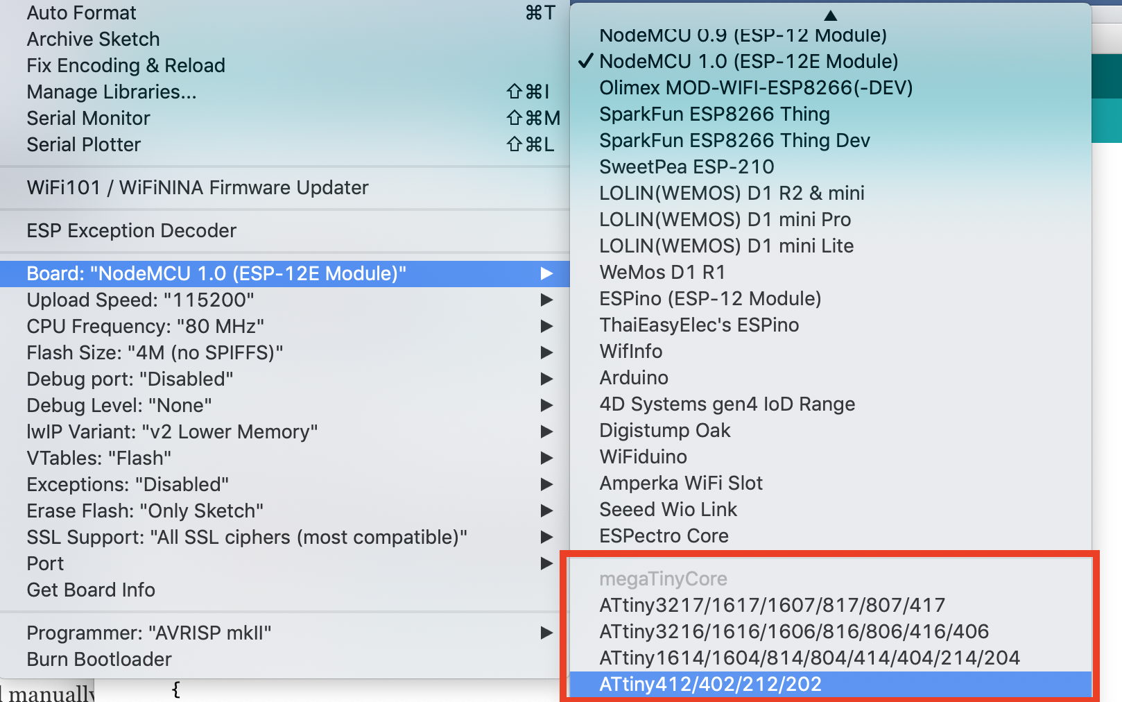
With all of that done successfully, you should now see the Attiny boards all listed under the boards’ section (tools -> Boards) of the Arduino IDE. If that is so, it means the board installation was successful.
2. Manual Installation
The Arduino board manager method provides some level of automation while the manual installation, on the other hand, allows the latest version of the core to be installed, with fixes that may not yet be available in the board manager version of the core. However, to use the manual installation, it is required that you use the board manager to install the latest version of the Official Arduino megaAVR board package for manual installation to work.
Manual installation is recommended if you are interested in contributing to the development of the core, or if having the latest fixes which are not in the released version is important to your build.
To install manually, follow the steps below;
Ensure you have installed the latest version of the Official Arduino megaAVR board package.
Download the MegaTinyCore.zip package (either the “released” version or by downloading the .zip of the master repo) on your computer.
Extract, and place the file in the “hardware” folder inside your sketchbook folder (where your Arduino Sketches are saved). If the hardware folder does not exist, create a new folder and name it “hardware”.
Restart the Arduino IDE
For automatic updates, instead of downloading the zip file, you can download the GitHub client, and sync this repo to the hardware subfolder of your sketchbook folder.
With the installation steps completed, you should now see the Attiny boards all listed under the boards’ section (tools -> Boards) of the Arduino IDE if the installation was successful.
Transforming the Arduino nano to a UPDI Programmer
Another challenge in the use of the ATtiny chip is the way they are programmed. They use a system called the Unified Program and Debug Interface (UPDI for short). This interface uses the RESET pin to program and/or debug the device. Thus, we need to transform the Arduino nano to a UDPI programmer which will send the correct signals to the UPDI/Reset pin.
To do this, we will use the UPDI Arduino sketch created by ElTangas. The sketch converts ATmega328(p)-based Arduino’s, like the Arduino UNO, Nano, and Pro mini, into a UPDI programmer. The sketch, however, does not work on boards based on other microcontrollers, like the 32u4 (on Arduino Micro/Leo) or non-AVR board.
The following steps show how to do this;
Close all instances of the Arduino IDE to avoid errors.
Open the jtag2updi folder after extracting the download
Open the sketch jtag2updi.ino and upload it to the Arduino board you will like to use, which for our sake is an Arduino Nano. When you open the code, the .ino file will appear empty and that is fine as all the code is contained in the other files in the same folder as the .ino, but the empty .ino is needed so they can be compiled by the IDE.
With the upload successful, you are now ready to use the UPDI programmer. If you use the new ATtiny series a lot, it will be a smart move to totally dedicate an Arduino pro mini or nano board as a permanent UPDI programmer.
Uploading Code to the ATtiny
To show the project in action, We will upload the Arduino blink example to the ATtiny. The Arduino blink example needs no introduction so I won’t bother to go over the code.
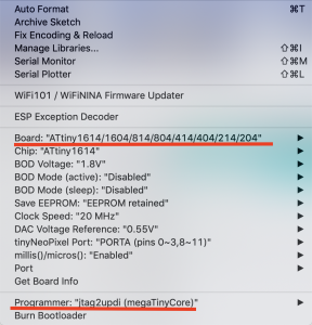
With the Arduino Nano connected to the ATtiny as described under the schematics section, open the blink example by going to File->Examples->Basics->Blink.
With the example is opened, select the board type and set the programmer (Tools->programmers (scroll towards the end)) as jtag2updi (megaTinyCore).
Add the line of code below, before the setup() function to indicate the pin to which the led is connected (since the chip doesn’t have a built-in LED)
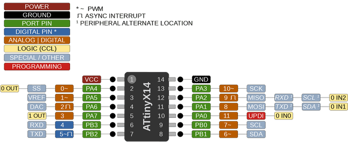
#define LED_BUILTIN 0 //PA4 (Pin 2)
An important thing to note at this point is the pin map below which shows how the Physical IOs should be referenced with Arduino C functions like digitalRead, digitalWrite, analogRead, or analogWrite. For instance, PA4 which is labeled as pin 2 on the chip is referenced as 0 within the Arduino IDE.
Pin Map
Also note that, unlike the ATmega328 MCU, the new ATtiny processors don’t have separate analog pins. All can be used as either analog or digital, depending on how it is declared within the code.
With the above done, verify the code and hit the upload button. You should in time begin to see the LED blinking. At this point, feel free do disconnect the Arduino nano and power the ATtiny from a 5VDC source.
Demo (credit: John Bradnam)
That’s it!
You can now deploy the new ATtiny series of microcontrollers in your project. Saving space and money. Unlike the former ATtiny microcontrollers, these new series of MCUs come with a higher amount of flash memories, cost a whole lot less, and are all-around more efficient. I advise they should be considered as the MCU of choice for your next tiny, low-cost, low-power project.
This article will present the different physical quantities that can be encountered in the electrical domain.
First of all, we present the most common electrical quantities by giving a table that summarizes all the different parameters associated with their unit, symbol, and measuring device. Moreover, we propose a large range of multiples and submultiples to use in order to simplify the writing.
In the second section, we present the International System of Units which is important to understand some specificities that apply to the electrical quantities. We focus on how the system is built around the defining constants and base units.
In the third section, we will focus on the electrical current, which is, in fact, the base physical quantity used to describe all the other electrical quantities.
Electrical quantities
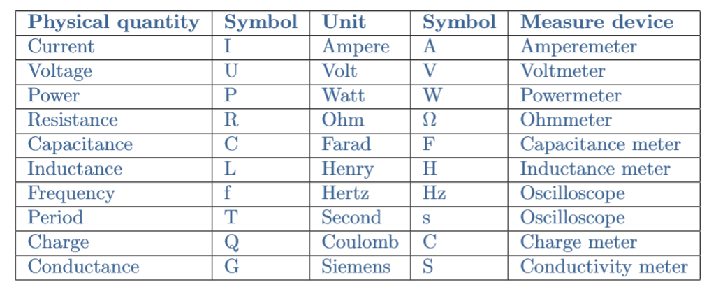
The following Table 1 presents the most important electrical quantities:
tab 1: Electrical quantities with their associated unit, symbol, and measure device
These quantities can vary on a large range of values, especially the current, resistance, and capacitance. For this reason, it is important to associate multiples and submultiples to them.
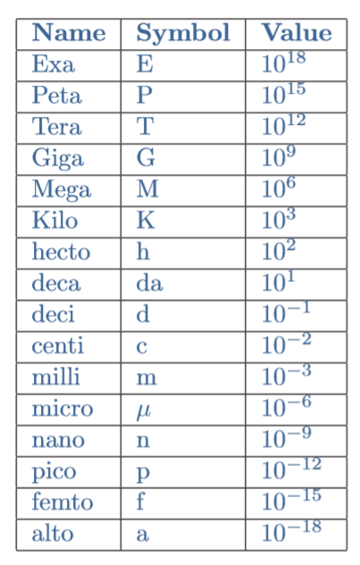
The following Table 2 gives a large range of submultiples and multiples, detailing their names, symbols, and values:
tab 2: Multiples and submultiples used in electronics
The International System of Units
SI Defining Constants
SI is the French abbreviation that stands for the International System of Units, it is the modern scientific metric system of measurement. This system is based on the defining constants which are fundamental properties of matter.
There are seven SI Defining Constants:
The hyperfine transition frequency of Cs
The speed of light
The Planck constant
The elementary charge
The Boltzmann constant
The Avogadro constant
The luminous efficacy of 540 THz radiation
SI Base Units
For each fundamental constant presented previously, a SI Base Unit is associated with:
The second (s) represents the time
The meter (m) represents the length
The kilogram (kg) represents the mass
The Ampere (A) represents the electric current
The Kelvin (K) represents the temperature
The mole (mol) represents the amount of substance
The candela (cd) represents the luminous intensity
SI Derived Units
The SI Derived Units are constructed around the SI Base Units, a great number of derived units exist and for this reason, but we will not list all of them.
There are however 22 named derived units such as the Newton (N), Pascal (Pa), or the ones presented previously in Table 1 such as the Volt (V) and Power (P).
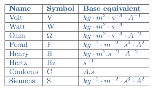
Any derived units are a combination of base units, we present this link in Table 3 for the relevant derived units of this tutorial:
tab 3: Electric derived units with their base unit equivalent
Application to electricity
The Defining Constant: Elementary charge
The defining constant that is relevant in this article is the elementary charge which numerical value is e=1.602176634×10⁻¹⁹ C (or A.s). This value corresponds to the smallest amount of charge that can be found in nature: a proton is positively charged +e and an electron is negatively charged -e.
The electric charge is an intrinsic property of elementary particles that such as the mass is easy to experience but hard to properly define. Charges of opposite sign attract each other, which explains why electrons keep orbiting around nuclei, while charges of the same sign repel each other, similarly than with magnets.
The Base Unit: Ampere
The base unit Ampere represents the transport of an amount of electric charge per unit of time across a certain section of material. In fact, the SI definition of the Ampere is “a current of one ampere is one coulomb of charge going past a given point per second”.
This transport of charges is precisely what is commonly known as the electric current. We can note that due to the small value of the elementary charge, even a small current corresponds in fact to a very large number of charges transported. As an example, a current of 1 mA approximately corresponds to the transport of the astonishing number of 6.2×10¹⁵ charges per second.
The Derived Units in electricity
It is important to note that every quantity presented in Table 1, except for the frequency and period, is derived from the current as we pinpointed in Table 3. The Ampere unit is indeed a fundamental unit derived from the definition of the elementary charge.
The Volt is defined as the potential difference that results in power dissipation of 1 W across a resistor of 1 Ω in when an electric current of 1 A is observed. From this description, the definitions of both the Ohm and the Watt can be given by rephrasing the previous sentence.
The Farad is defined as an increase of charge of 1 C in a conductor when 6,241 × 1018 electrons are added to it. It is the derived unit for the capacity which represents the ability of a conductor to store charges when submitted to a potential difference.
The Henry is the derived unit for the inductance, it is defined as the production of a potential difference of 1 V when a circuit/component is submitted to a variable electric current of 1 A/s.
Conclusion
This short tutorial has focused on the most important units to measure electricity-related parameters. First of all, we gave a table that presents the most common and important electrical quantities with their associated unit, symbol, and measure device.
In the second section, we have focused on the International System of Units which gives us the basis to understand the distinction between units and quantities. We also highlight the fact that the Ampere, which is the SI unit for the electric current, is a base unit and is used to express any other electrical unit, which are called derived units.
Finally, the last section defines in detail the elementary charge defining constant, the ampere base unit, and some derived units for the electricity domain such as the volt, ohm, watt, farad, and henry.