BLYST Nano is a tiny ARM Cortex Module with Bluetooth and 30 I/O, but next product BLYST840 is a finger-tip size, 32-bit ARM Cortex-M4F module with Bluetooth 5 and 46 I/O; a powerful upgrade of a system on a module indeed.
Built around the Nordic nRF52832 Bluetooth SOC and the powerful 64MHz ARM cortex- M4Fprocessor, the new BLYST840 from I-SYST can be described as an advanced and highly flexible chip solution to the rising demand in ULP wireless applications for IoT devices.
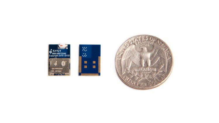
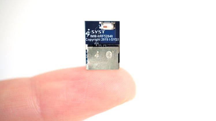
With dimensions smaller than a US quarter coin, the 14 x 9 x 1.6 mm BLYST840 packages everything an IoT device needs into a fingertip-sized module. The BLYST840 contains a CPU ( ARM Cortex-M4F), 46 I/O pins exposed to pads around the module for easy assembly, coils for low-power DC/DC mode, built-in ceramic antenna, encryption co-processor, NFC antenna, DC/DC converter, built-in 32 MHz and 32.768 MHz crystal for low power applications and requires no extra PCB space for supporting components. The BLYST840 also features an on-board regulator that accepts an input voltage of 5.5V and up to 25 mA for an external circuit.
While the BLYST840 maintained a lot of similarities with I-SYST last product, the BLYST Nano, it comes with several features that put it a few pedestals higher with 46 I/O pins, more wireless protocols like Thread and Zigbee added to the existing Bluetooth 5 support, and support for Micropython. The extensive availability of the memory (1MB flash and 256 KB RAM) together with the 32-bit ARM Cortex M4F running at 64 MHz also allows for quick and more efficient computation of complex functions.
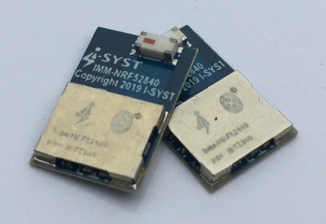
The tiny BLYST840, gets you covered anytime, either in hand-assembly prototyping or in production as the pads are designed in such a way that it can be easily mounted on a board for reflow soldering or hand soldering. It also comes with most of the needed wireless certifications including FCC, IC, and CE, so you can integrate directly into your project without worrying about those certifications.
Finally, a number of software development resources are freely available for both the MicroPython ports and the nRF52840. The module is supported by the open-source multi-architecture and multi-platform IOsonata design library, that supports a wide range of microcontrollers used for IoT designs.
The BLYST840 is currently not out for sale, but I-SYST plans to launch a crowdfunding campaign on Crowd Supply for the board, with prices starting at $18. This might be a good opportunity to get access to the board early. In the meantime, you can visit the pre-order page for more details about the module.
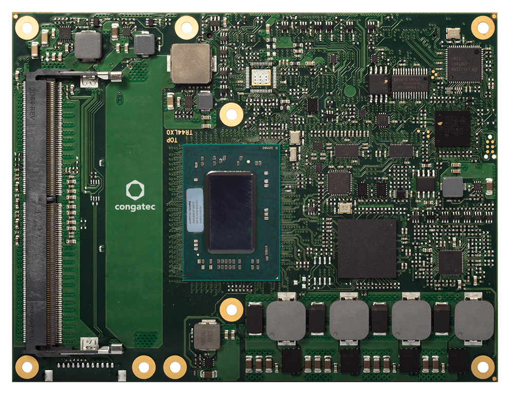
congatec – a leading vendor of embedded computing technology – introduces its new conga-TR4 COM Express Type 6 module with AMD Ryzen Embedded V1000 Series processors for the industrial temperature range from -40°C to +85°C. It is available with optional burn-in & cold-soak stress screening services for the highest reliability. The most demanding graphics and compute workloads benefit from the modules’ 4 cores, 8 threads and 8 GPU compute units delivering the well-reputed massive processing throughput of AMD’s Zen microarchitecture in an ultra-rugged shape. The TDP is scalable from 12W to 25W enabling truly immersive 4k UHD system designs with passive cooling only. Typical applications for the new industrial-grade COM Express modules can be found in rugged edge computing with embedded vision and artificial intelligence (AI), autonomous vehicles, railcars and wagons, outdoor equipment in the oil and gas industries, mobile ambulance equipment, broadcasting vans, or insecurity and video surveillance, as well as base station equipment for 5G, to name just a few.
The maximum performance of the new conga-TR4 COM Express Type 6 module depends on the environmental conditions and is specified with 1.6 GHz to 2.8 GHz turbo boost in the sub-zero temperature range, and 2.0 GHz to a maximum of 3.6 GHz in the positive temperature range. The impressive performance of the ultra-rugged conga-TR4 Computer-on-Modules has been made available in a real-time capable design and also includes real-time hypervisor support by Real-Time Systems for virtual machine deployments and workload consolidation in edge computing scenarios.
The feature set in detail
The new conga-TR4 high-performance module with COM Express Type 6 pinout is based on the latest AMD Ryzen Embedded V1404I multi-core processor for the industrial temperature range. It supports up to 32GB energy-efficient and fast dual-channel DDR4 memory with up to 3200 MT/s and optional ECC for maximum data security. The integrated AMD Radeon Vega graphics with 8 compute units marks the cutting edge of embedded graphics. It supports up to four independent displays with up to 4k UHD resolution and 10-bit HDR, as well as DirectX 12 and OpenGL 4.4 for 3D graphics. The integrated video engine enables hardware-accelerated streaming of HEVC (H.265) video in both directions. Thanks to HSA and OpenCL 2.0 support, deep learning workloads can be assigned to the GPU. In safety-critical applications, the integrated AMD Secure Processor helps with hardware-accelerated RSA, SHA, and AES encryption and decryption.
The new conga-TR4 allows a complete USB-C implementation on the carrier board including USB 3.1 Gen 2 with 10 Gbit/s, Power Delivery and DisplayPort 1.4, for example to connect external touchscreens with a single cable. Further performance-oriented interfaces include 1x PEG 3.0 x8, 4x PCIe Gen 3 and 4x PCIe Gen 2, 3x USB 3.1 Gen 2, 1x USB 3.1 Gen 1, 8x USB 2.0, 2x SATA Gen 3, and 1x Gbit Ethernet. I/Os for SD, SPI, LPC, I²C as well as 2x legacy UART from the CPU and High Definition Audio round off the range of interfaces. The supported operating systems include Linux, Yocto 2.0 and Microsoft Windows 10, or optionally Windows 7.
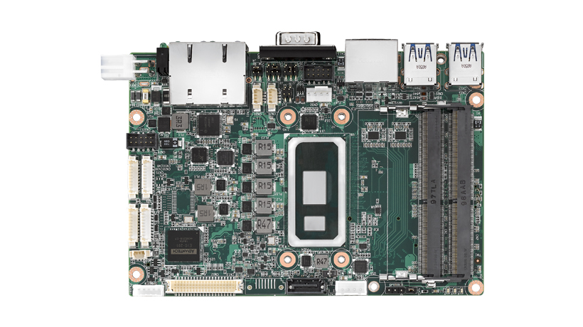
Advantech (2395.TW), a leading global provider of IoT systems and embedded platforms, is pleased to announce the latest 3.5” SBC MIO-5373 based on the 8th Gen. Intel Core platform with low-power SoC. Featuring compact 146 x 102mm dimensions, the MIO-5373 design not only offers impressive I/O functionality but also provides domain-focused features like CANBus and wide-ranging power input. It is ideally suited for use in application fields like medical equipment, automation control systems, outdoor kiosks, and areas requiring small-size adoption with Intel Core-level computing performance.
Quad-Core Performance and High Speed NVMe x4
The new 8th Gen. Intel Core low-power SoC (codename: Whiskey Lake-U) is the first generation to double the computing cores from dual to quad. This new generation provides double the computing performance with 15W power consumption. Featuring a built-in Gen9LP graphics engine, MIO-5373 supports three simultaneous displays through LVDS/eDP, HDMI, and DisplayPort interfaces up to 4K resolution, as well as H.265/HEVC, H.264/AVC, MPEG2 hardware decode/encode. Dual channel DDR4 supports up to 32GB/64GB* and the M.2 M-Key 2280 NVMe x4 supports high-speed PCIe SSDs to provide an extremely high data rate for computing and storage. Enhancing overall system performance—rather than just that of the core processor—makes it well-suited for image processing in medical applications and heavy loading content kiosk displays.
Domain-Focused I/O and Flexible Expansion
MIO-5373’s built-in iManager3.0 is based on Advantech’s EIO-201 embedded controller which integrates power sequence control for higher reliability and generic functions including GPIO, hardware monitoring, smart fan control, and watchdog timer. It also has domain-focused features like high-speed RS-232/422/485 up to 1Mbps, I2C (100kb/400kb/1Mb), and CANBus. iManager provides I/O functionality in company with drivers and software APIs on both the Windows and Linux operating systems to make it easier for software development. MIO-5373 provides adequate expansion for a variety of function cards, including: M.2 E-Key for WiFi+BT, or AI acceleration card; M.2 B-Key for 3G/LTE modules, or SATA SSD; and M.2 M-key NVMex4 with optional SATA SSD. What’s more, Advantech’s MIO Extension interface provides 4 x PCIe x1/USB/LPC/SMBus slots for vertically-focused or customized expansion. The MIOe-260 I/O module provides an additional 2 x GbE, 8 x UART, 4 x USB, and 2 x CANBus with isolation, miniPCIe socket, and a M.2 B-key socket. Together with MIO-5373 and MIOe-260, it enables factory automation processes for AGV, CNC machines, and medical equipment I/O requirements.
Wide-Ranging Power Inputs and an Extended Operating Temperature Range
MIO-5373 is designed with a wide-ranging power input from 12~24V that caters to factory power rail and outdoor equipment with HVAC systems inside. To deal with extreme outdoor temperature conditions, MIO-5373 provides variant SKU supporting operation from -40°C to 85°C. The advanced thermal solution leverages four symmetrical heatsink screw holes around the CPU to dramatically lower thermal resistance and help heat quickly dissipate into air. MIO-5373 effectively solves temperature and thermal issues that often confront outdoor kiosks, railways, and crucial factory environments.
WISE-PaaS/DeviceOn: Value-Added Software and Cloud-Based Manageability
MIO-5373 provides ready-to-use Windows 10 and Ubuntu images in company with iManager software API and utility. Advantech’s WISE-PaaS/DeviceOn—IoT device operations and management software—makes it easy to integrate, visualize, operate, and manage industrial IoT devices through public or private cloud. With DeviceOn’s easy-to-use interface, users can monitor device health, enjoy real-time control over power on/off, troubleshoot, and perform updates over-the-air (OTA), on-site and remotely.
Product Features and Specifications:
8th Gen. Intel® Core i7-8665UE/i5-8365UE/i3-8145UE
Dual channel DDR4-2400MT/s with up to 32GB, onboard eMMC 32GB
Triple display by 48-bit LVDS/eDP+HDMI+DP, up to 4K resolution
Dual GbE, 4 x USB3.0, 2 x RS-232/422/485, CANBus, 12-24V input
M.2 E-key 2230 & M.2 B-key 2280 (SATA or 3G/LTE), optional M.2 M-Key 2280 for NVMe x4
MIO extension interfaces with 4 x PCIe (x1/x2/x4), USB, LPC, SMBus
Supports iManager software APIs for Windows 10 and Linux
Network Attached Storage (NAS) are high-capacity storage devices that are connected to a local home or office network to provide everyone (with designated “clearance”) on that network with access to the files on the drive without the need to plug into it directly. This facilitates things like in-house sharing of large files like movies and other multimedia, without the need to move drives around.
While high-grade consumer NAS Devices are readily available in stores, the advent of SOCs, and SBCs like the Raspberry Pi, has made Network Attached Storage one of the coolest things people build with SBCs. As a result of this, I recently decided it might be a good idea to share a tutorial, and while there were dozens of NAS DIY projects online, the project by Instructables user Aramybox caught my attention, and I will be chronicling his build for today’s tutorial.
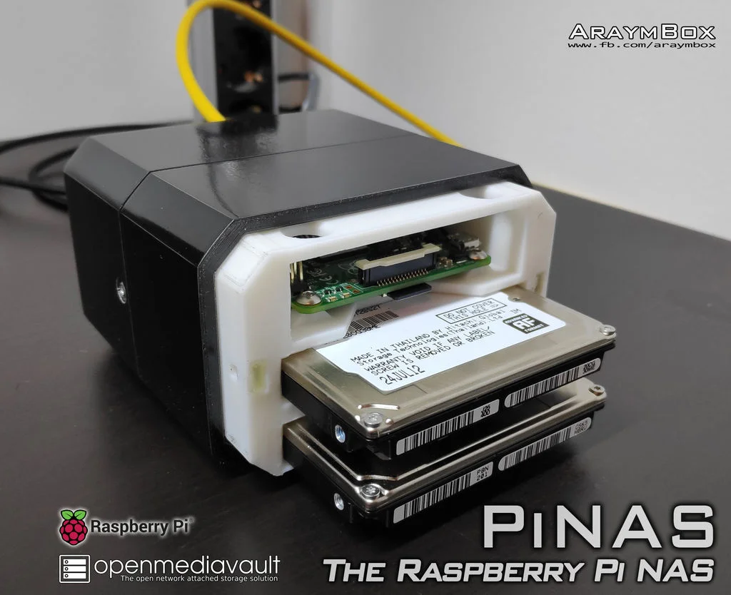
Aramybox‘s Project called the PiNAS, is one of the simplest and most elegant of DIY NAS Solutions I found online. The project is based on a Raspberry Pi with two Hard drives, all enclosed with an innovative, 3D printed Enclosure. Performing all the NAS Gymnastics at the heart of the project is the Open Media Vault (OMV) OS running on the Raspberry Pi. OMV is a Network Attached Storage (NAS) solution based on Debian Linux, that contains services like SSH, (S)FTP, SMB/CIFS, DAAP media server, RSync, BitTorrent client and many more. It is primarily designed to be used in small offices or home offices but is not limited to those scenarios. It is a simple and easy to use out-of-the-box solution that will allow everyone to install and administrate a Network Attached Storage without deeper knowledge.
The advent of single-board computers like the Raspberry Pi democratized access to solutions like this, giving users the ability to build powerful but cheap applications.
At the end of this tutorial, you should be able to build your own PiNAS and probably throw in some upgrades to Aramybox‘s work.
Required Components
The following components are required to build this project;
The bolts and nuts are based on the enclosure design by “Aramybox”. If you are going to create your own enclosure, with adjustments that may affect the bolt and nuts specifications, then you may need to ignore the ones listed and just get what works for you.
Enclosure Design
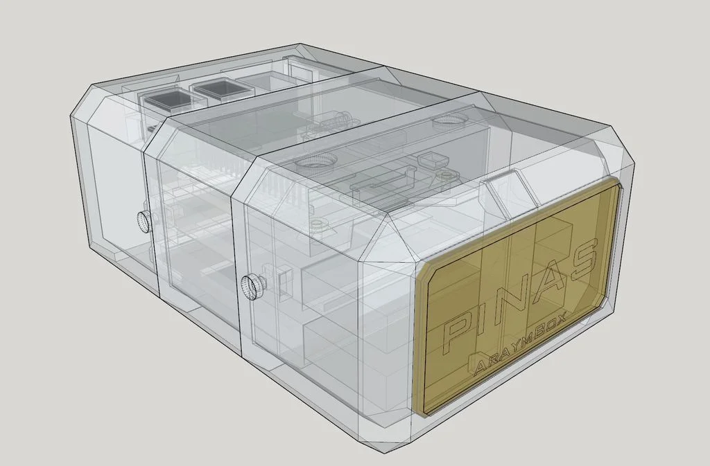
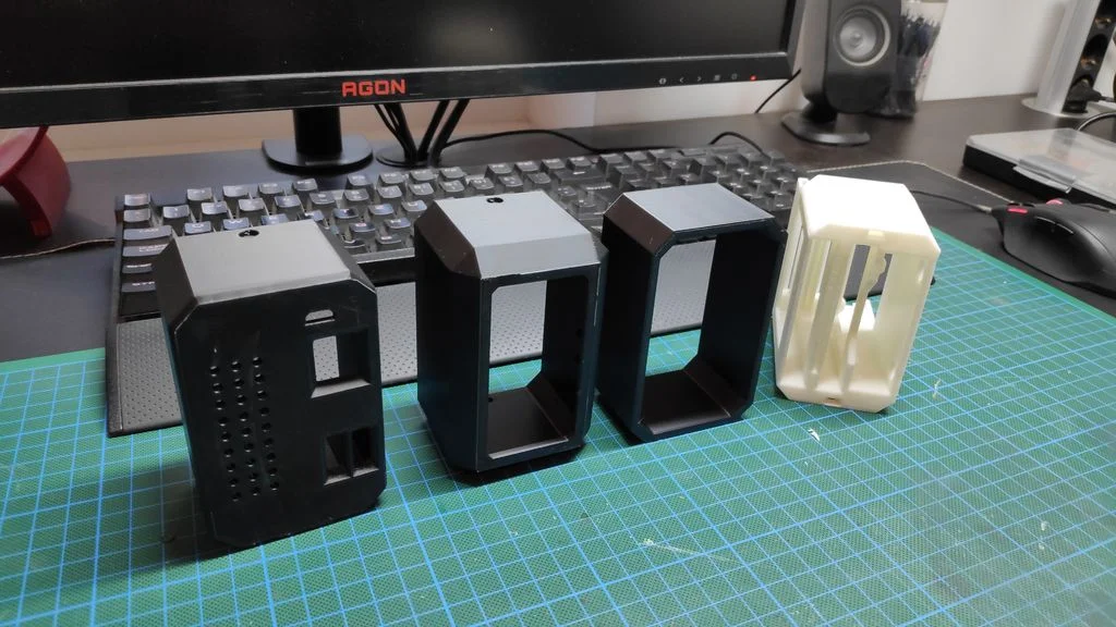
One of the best things about this project is the interesting enclosure that was designed for it. The enclosure which was 3D Printed comprises of only 4 parts and it was designed in such a way that it can be held together by just 4 bolts and can be opened easily to switch the drives or perform other maintenance.
To make the enclosure easy for people to replicate, the STL files are attached in the download section at the bottom of the page. You can also access the design files via project’s page on Thingiverse.
For printing materials, Aramybox used PLA for the inner part and ABS for the three outer shells. To improve the outlook of the enclosures and remove some of the imperfections due to 3D printing, a couple of Sanding paper, and painting actions were carried out.
Schematics and Components Connections
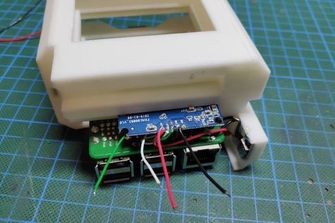
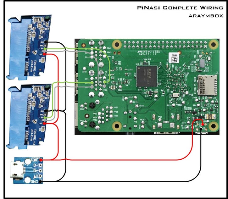
To make the project compact, “Aramybox” opened up the SATA to USB Adapters and desoldered the wires that go from the HDD end to the USB end. With the aid of jumper wires, the salvaged HDD end of the adapter is then soldered directly to corresponding pins on the USB ports of the Pi. Enough care should be taken at this point to ensure the Pi is not damaged and the existing connections on the board are not bridged. Asides the SATA connectors, “Aramybox” also connected a female MicroUSB power board to the Pi. It will provide an easy way to Power the Pi and other components like the SATA connectors, all at once.
A schematics showing the described connections is provided below.
Schematics
In place of soldering the wires directly on the SATA connector, you can choose to use male/female header pins. Just to make things neat and presentable.
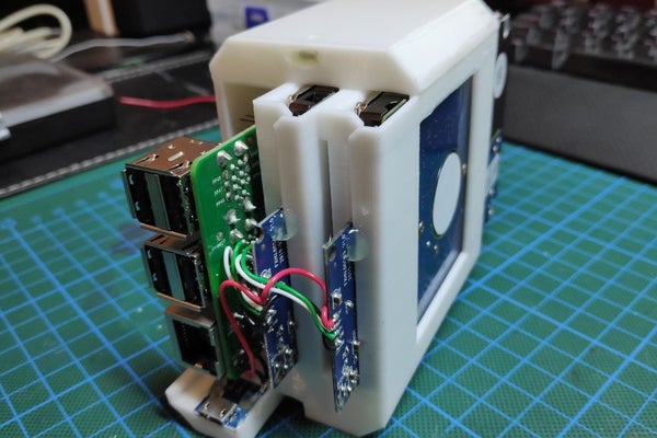
The setup with all the components connected should look like the image below.
With this done, we are ready to explore the software for the project.
Software and Configurations
To make our setup function as a NAS, we will use a modified version of the Raspberry Pi OS called; Open Media Vault, as the brain of the project.
We start the process by flashing the SD card with an image of the Open Media Vault OS. At this point, I will assume you understand how to flash an SD Card with a Raspbian OS using tools like Balena (for macOS and Windows users). If you are completely new to this task, then you can check out some of our tutorials that cover that topic online.
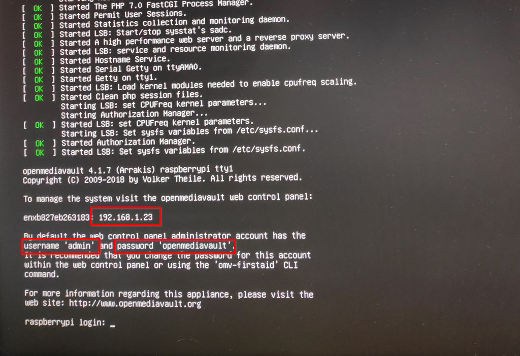
With the SD card successfully flashed with the OS, install the card into its slot on the Pi, connect the Pi to your network via an Ethernet cable, and power up the system. Powering up the setup for the first time, it is advisable to have a monitor connected to the Pi. This will allow you to access important information like the IP Address, along with Username and Password
With this info obtained, you can now disconnect the Pi from the monitor and proceed to configure Open Media Vault. 5 main sections of the Open Media Vault needs to be configured are:
System
Storage
Access Rights Management
Services
Diagnostics
Follow the steps below as described by “Aramybox” to configure these sections:
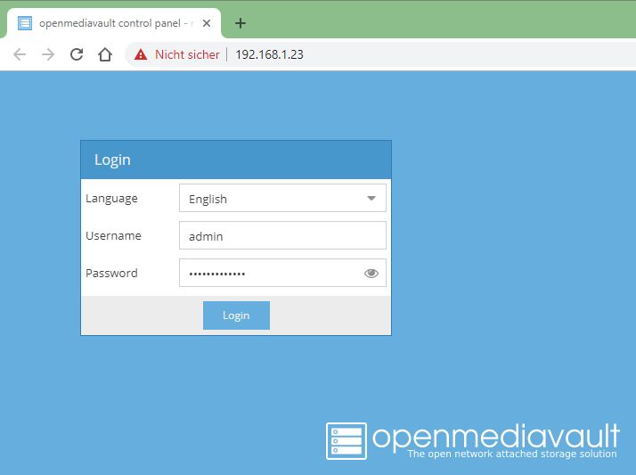
1. With the IP Address, Username, and Password all at hand, launch your favorite internet browser (firefox, chrome, ie, etc.) on a device (PC, smartphone, etc.) that is on the same network as the Pi.2.
2. Type in the IP-address of the PiNAS into the address bar of the browser.
3. You should now see the authentication screen of Open Media Vault.
4. Enter the username, password and click Login.
5. After successful Login, we proceed to the configurations starting with the System configurations.
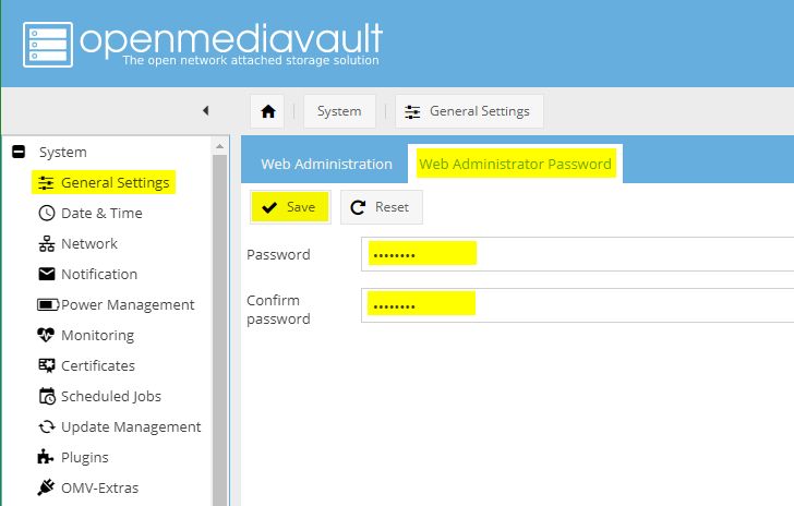
6. For the system configurations, we start with security. To ensure security, it is important to reset the password and username to one you can remember. To do this, click on the general settings tab. on the resulting page, click on the Web Administrator Password panel and fill in the new password. Click on the Save button.
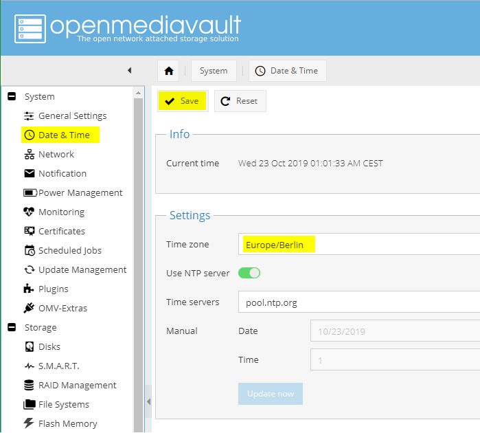
7. Next, we set the time and date of the system. Do this by clicking on the time and date tab. On the resulting window, select your time zone, enable the NTP (Network Time Protocol) feature, and set a time server. Click the save button to save this setting.
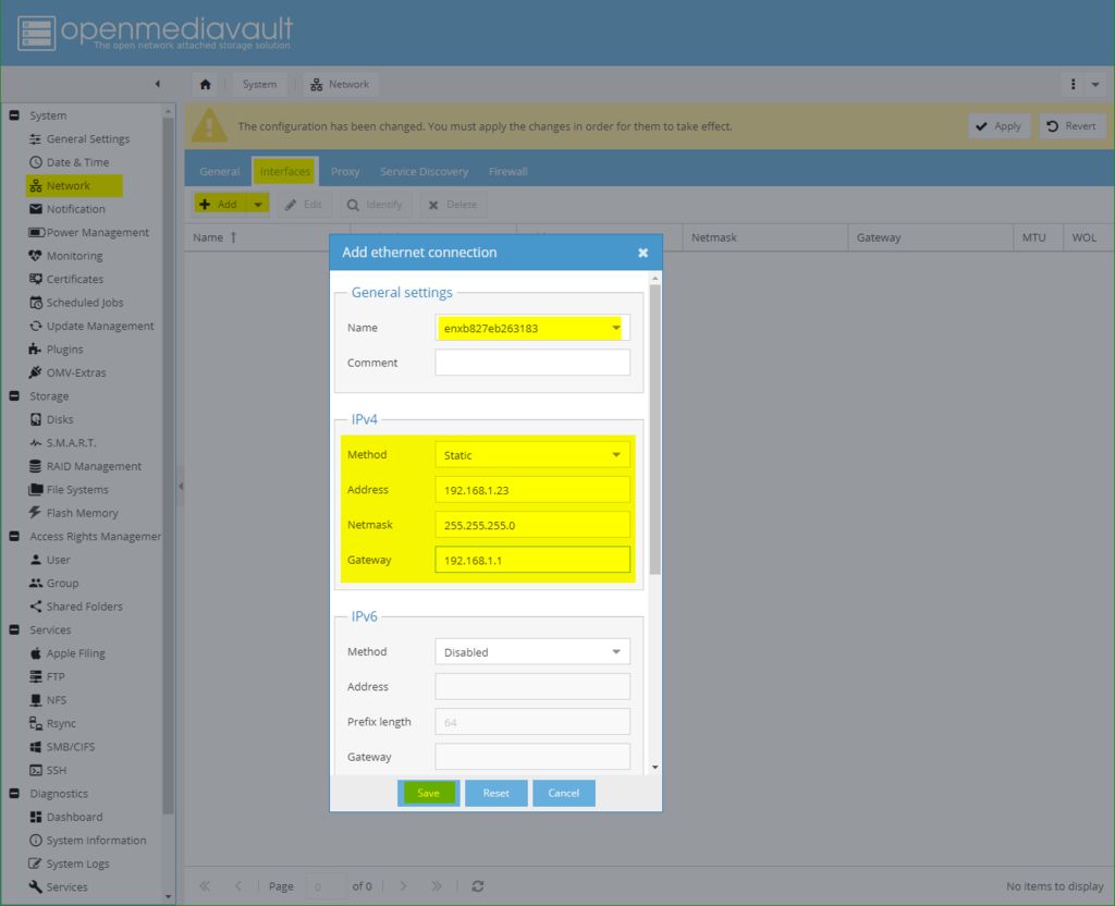
8. Next, we configure the network identity. Click on Network and go through each of the tabs giving your PiNAS a hostname, Set a Static IPv4 address so it does not change after reboot, and activate the services you desire in the Service discovery tab.
9. Next, we configure parameters related to Storage. under Storage, we will set up the disks, RAID management, and a filesystem for easy addressing.
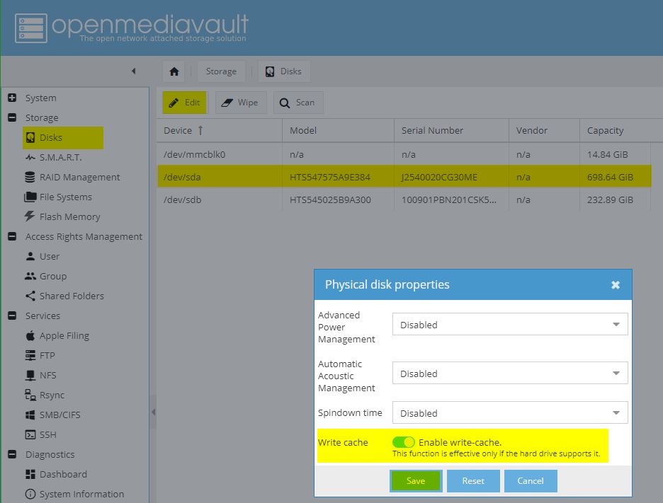
Disks
Click on the Disks button
Make sure both hard drives were identified and listed on the resulting page
Run through the following steps for both disks:
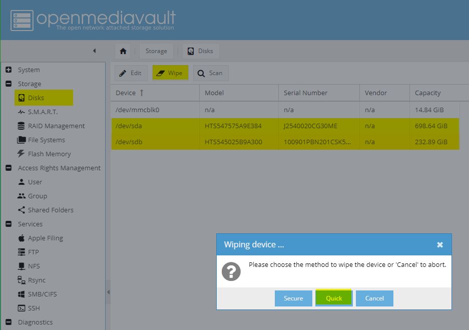
i. select the disk, click Edit and enable write cache. ii. Select the disk, click Wipe, and click on the quick button to wipe all data from the disk and give the system a clean slate to work with.
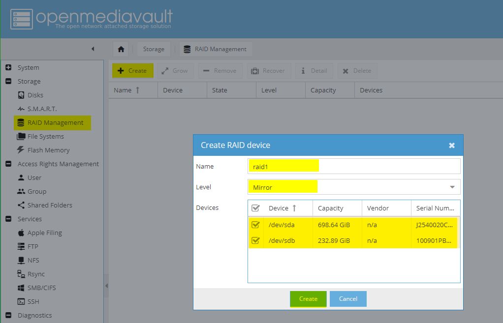
RAID Management
1. Select RAID() management in the dropdown on the right and click on the create button.
2. On the resulting window, fill In parameters like the name of your RAID e.g. raid1, the RAID Level e.g Mirror (RAID Level 1), Select devices you want to add to the RAID (select both your disks).
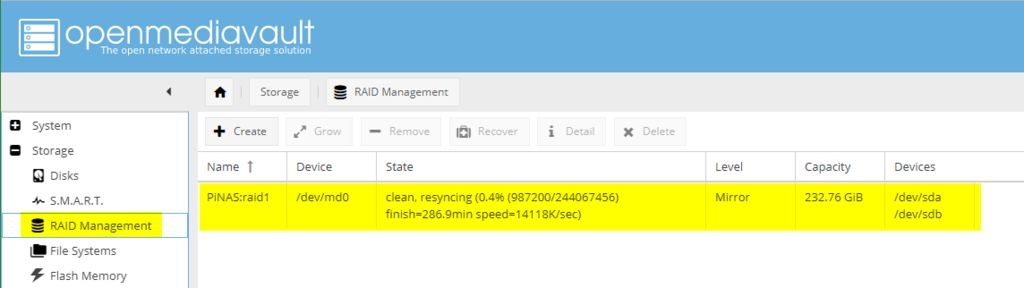
3. With the above done, Click Create to create the RAID using the selected disks. The RAID should take some time to re-sync. After syncing, the state of the raid would change to clean.
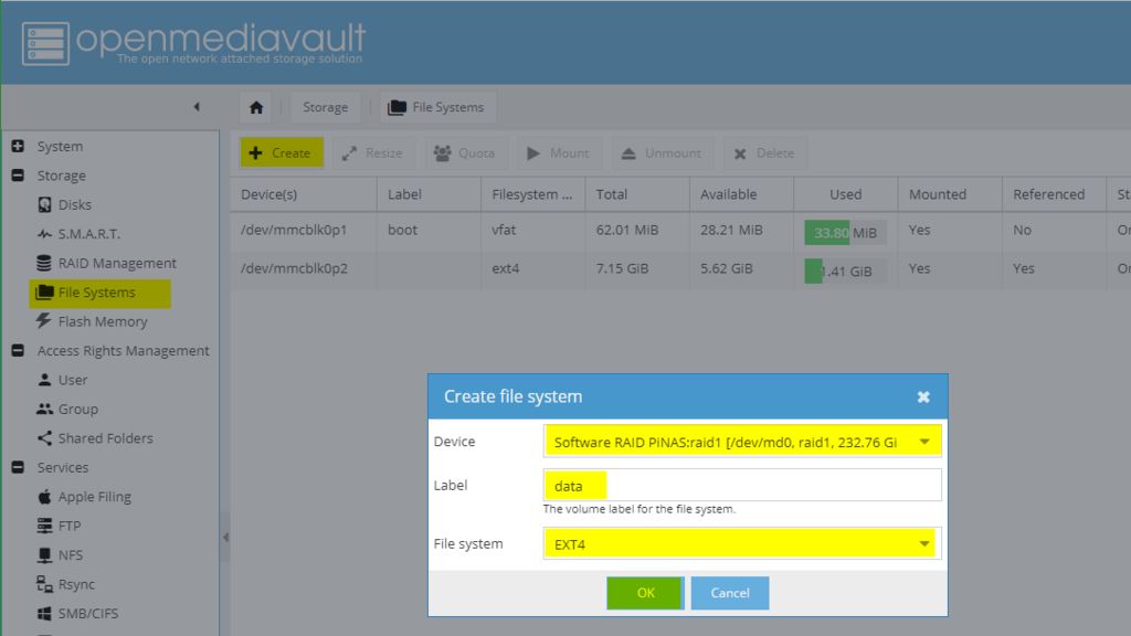
File System
Select File Systems in the dropdown on the right and click on the create button.
Select your Device which in this case should be the previously created “raid1”(or whatever name you gave it)
Give your file system a Label to identify it easily
Wait for your file system to finish initializing (Status has to be Online)
Select your initialized file system and press Mount to make it available
Next, we go through configurations related to Access Right Management. For this, we will create users and user groups which will be used to assign access. we will also be creating shared folders so the file system on the PiNAS can be accessed similarly to how files are accessed on PCs.
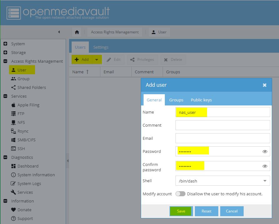
Create Users
User accounts are necessary for file system access.
Expand the Access Rights Management dropdown and click on the user’s tab.
Click “Add” to create a new user and in the resulting window, fill in the Name, and password, and hit the “Save” button when done.
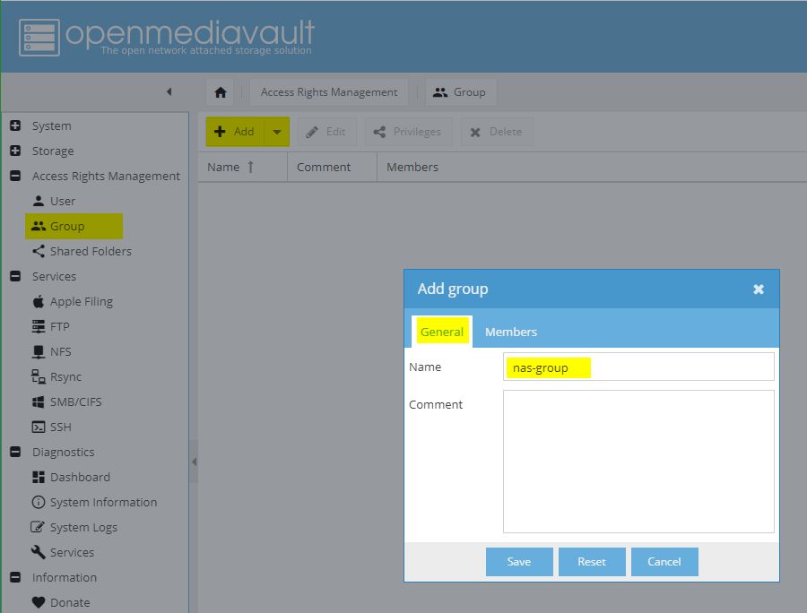
Create User Groups
User Groups makes it easy to manage access. For instance, you can restrict access to multiple users by, restricting access to their group. Follow the steps below to create user groups.
Click on the Group tab under Access Right Management.
Click “Add” to create a new user group.
On the resulting window,enter your preferred name for the group.
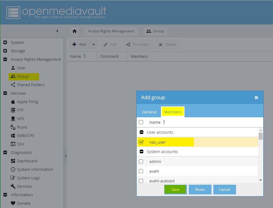
Select the users (must be created first) that you want in that group via the member’s tab. Hit the save button when done.
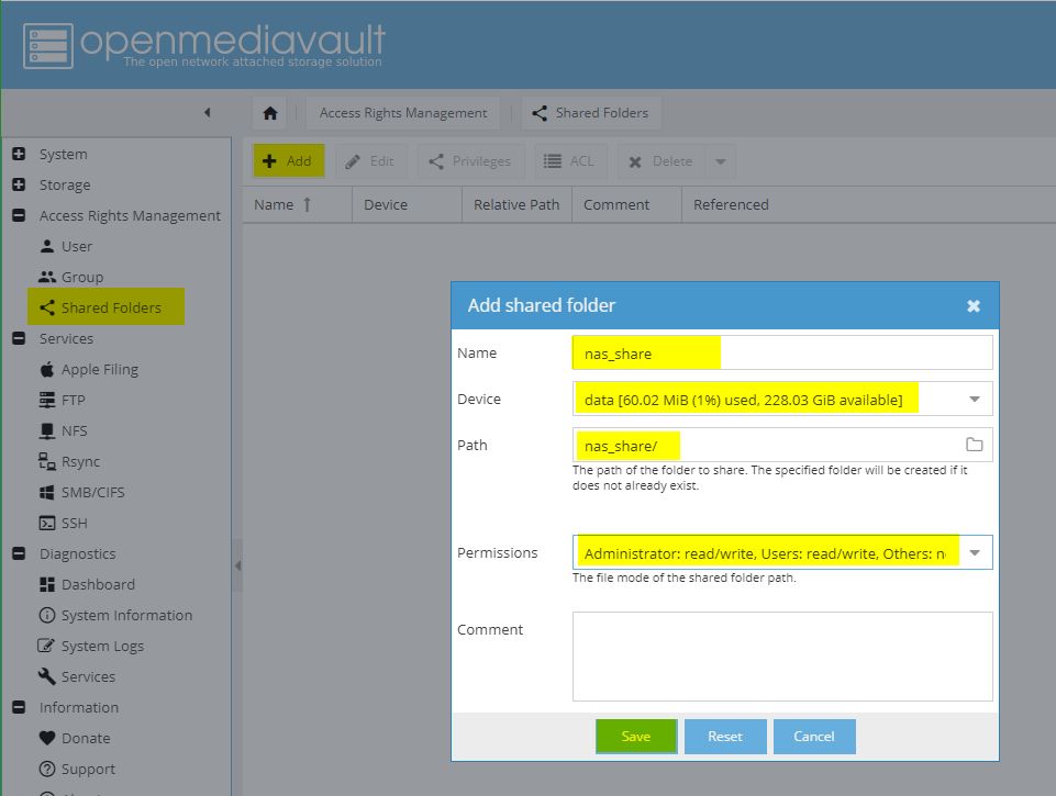
Create Shared Folders
Click on the shared folder under Access Right Management Window.
On the resulting window, click ”Add” to create a new shared folder
Enter a Name for the new share folder (this name will be connected to other machines)
Select the Device (your previously created file system) where the shared folder will be created on
Select or enter the Path of your shared folder
Set your desired Permissions for this shared folder (more permissions will be set in the next steps)
Click Save to create the shared folder
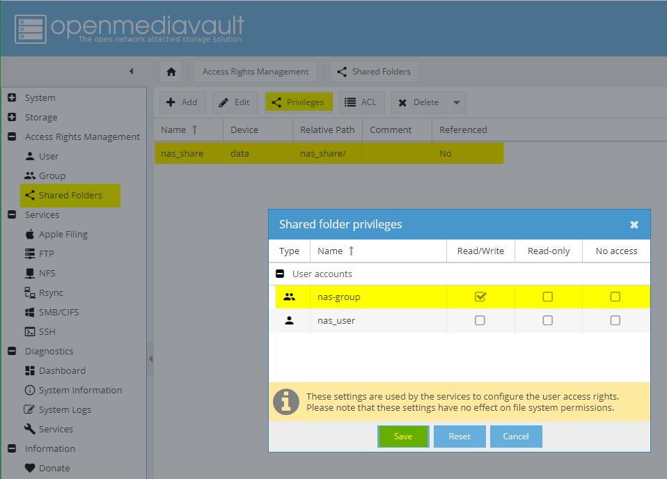
Click Privileges to set them for users or user groups
Set your desired privileges to your users or/and groups
Click Save to save your settings
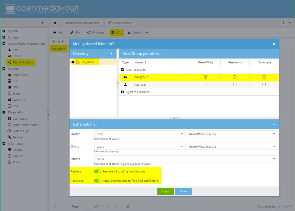
Click ACL to create a new Access Control List for your shared folder
Set your desired User/Group permissions (e.g. Read/Write) for your users and groups
Enable “Replace all existing permission” and “Apply permissions to files and subfolders”
Click “Apply” to create and apply the ACL
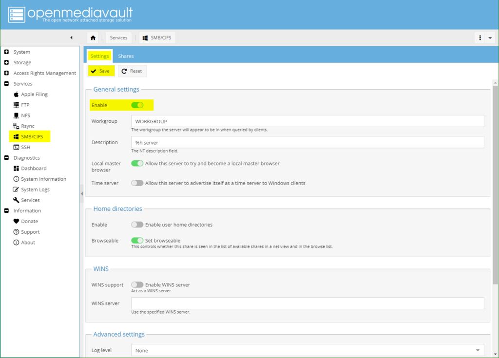
Finally, we need to configure the Services i.e how your PiNAS is presented to other devices in your network.
SMB/CIFS
Under the services section, we will only be configuring the SMB/CIFS section.
Expand the Services tab and select SMB/CIFS
On the resulting page, click the settings tab and enable SMB/CIFS
Open tab Settings
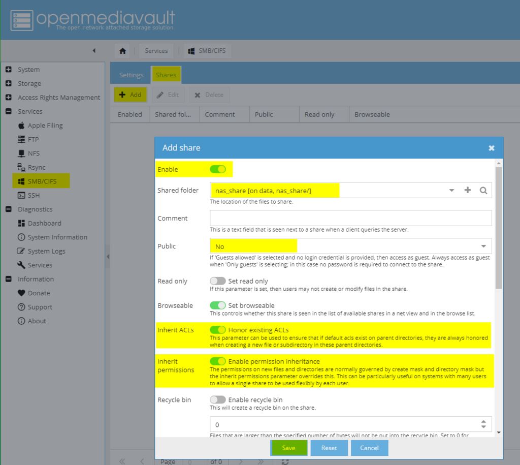
Next, click on the “Shares” tab and click on the “Add” button to create a new SMB share
Enable the new share
Select a shared folder (the one you created before)
Select if the share will be Public (visibly listed by PiNAS)
Enable Honor existing ACLs (inherit ACLs)
Enable permission inheritance
Finally, click “Save” to create the new SMB share
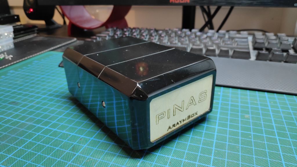
With all this done, Your PiNAS is now ready for use.
Using the PiNAS
After the configurations, you can now go ahead and fully enclose the PiNAS. It should look like the image below.
To use the PiNAS with your PC, it is important to connect the PiNAS share to your computer.
Follow the steps below to do this.
Press the Windows button on your keyboard, type cmd and press Enter. A Windows command prompt should pop up.
Type the following command to connect the PiNAS share:
net use N: \\PiNAS\nas_share
The command prompt should now ask you for a username to authenticate with. Enter the PiNAS username nas_user.
Now the command prompt wants the password for nas_user – type it in and hit Enter.
The command prompt should say something like The command completed successfully.
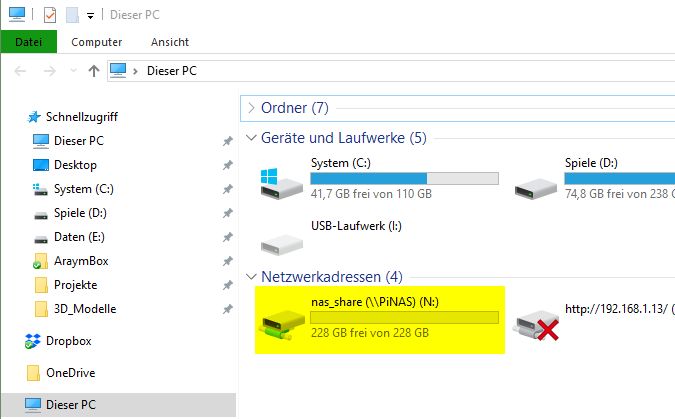
With this done, you should now see a new group; Network Location, when you open an instance of the Window Explorer.
The new group will contain all your mapped network folders – just like the connected nas_share, and you should now be able to drag and drop data to this drive and back it up on the two mirrored disks of the PiNAS.
That’s it for this tutorial. Feel free to explore and add more features to the project.
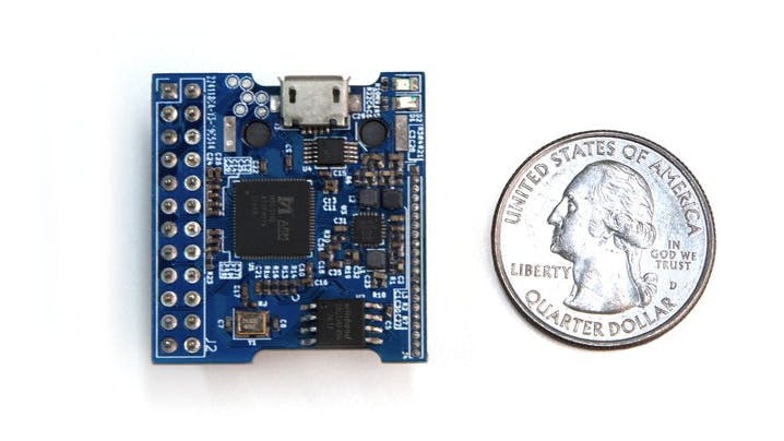
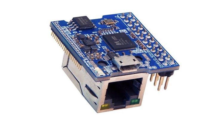
Measuring about 32 x 30 mm in footprint, Palmer’s fully-functional development board is a very small Linux-based single-board computer built around an ARM Cortex A7 SoC and targets IP cameras.
“There are no solutions yet that can run a real OS like Linux that can be integrated by hobbyists into boards from cheap PCB vendors that don’t have show-stopping limitations. The BreadBee is based on a relatively unknown IP camera SoC, the MSC313E, from a company called MStar. You might have never heard of MStar but you probably have one of their chips on your TV. The MSC313E has just enough of the usual microcontroller peripherals to make it useful, comes in a (relatively) easy to work with QFN package, is tiny, and costs $4. It is a bit harder to integrate into your designs than a microcontroller that requires a single power supply but all of the information you would need to do so is right here“,
explains Palmer as he prepares to launch a crowdfunding campaign for his new design.
The single-board computer, he said, is one that can be integrated into any project while reserving considerable space. Despite its very small form factor, BreadBee boasts of certain impressive specifications which include:
Single-core Arm Cortex A7 SoC running at 1GHz
64kB static RAM and 64MB of DDR2 memory
100 Mbit Ethernet
Bootable and memory-mapped SPI-NOR
4x 10bit ADC channels
2x SPIs, 1x 12C
3 x UARTs
Quite a lot of GPIOs
8x PWM pins
Real-Time Clock and Watchdog timer.
USB PHY and host/device mux
SD / SDIO interface
32mm x 30 mm in size
The chip has also quite a number of features like the camera interface and h264 encoder for IP camera duties, hardware cryptographic acceleration, command-queue direct memory access controller, audio ADC / DAC, IR decoder and 8051 low power mode management MCU that are yet to come to their prime.
There is no price attached to the BreadBee yet, but Palmer hopes that production costs per unit would be around $10. More details on the board can be found on it’s GitHub repository or on Crowd Supply where Palmer plans to launch a live crowdfunding campaign.
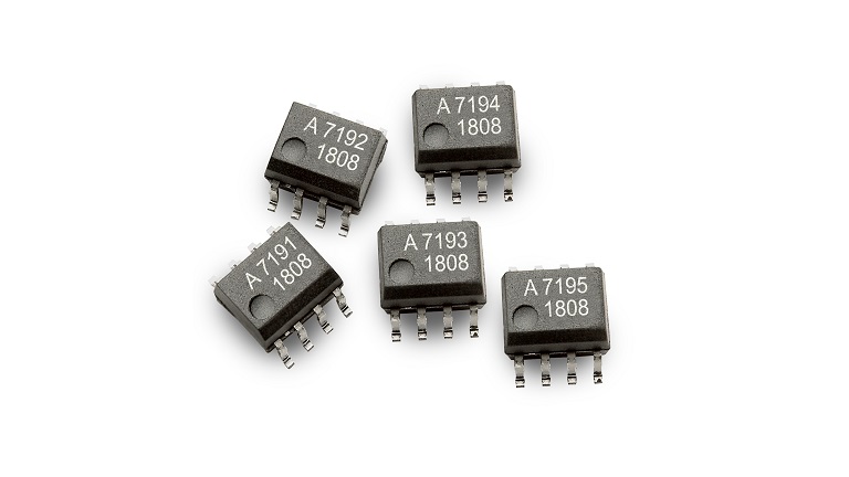
The ACHS-719x product series is a fully integrated Hall Effect-based isolated linear current sensor device family designed for AC or DC current sensing
The ACHS-719x product series is a fully integrated Hall Effect-based isolated linear current sensor device family designed for AC or DC current sensing in industrial, commercial, and communications systems. The family consists of products with a sensing current ranging from ±10 A to ±50 A. The devices offer a precise, low-offset, linear Hall circuit with a copper conduction path located near the surface of the die. Applied current generates a magnetic field that the Hall IC converts into a proportional voltage. Device accuracy is optimized through the use of differential Hall transducers.
Key features
Wide Operating Temperature Range: from -40ºC to 110ºC
Primary Conductor Resistance: 0.7 mΩ Typ.
Sensing Current Ranges: ±10A, ±20A, ±30A, ±40A, and ±50A
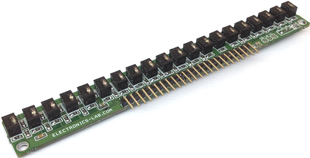
This project consists of 20 non-contact infrared reflective sensors and each sensor provides an analog output. QRD114 sensor is the heart of the project which includes Infrared LED and photosensor. The output of each sensor is high and goes low as objects or lines detected. The analog output voltage is proportional to IR reflected back to the sensor. The project has been designed to be used in robotics applications for line follower or multi-object sensor. Sensor requires 5V DC to work, all LEDs have current limiting resistors, each output has a pull resistor, and the normal output of each sensor is high due to the pull-up resistor and goes low as object or line is detected. IR LEDs power ON/OFF can be controlled using Q1 BD140 PNP BJT transistor which requires a low voltage for normal operation or all IR LED and can be powered up to 5V DC with help of VL input pin. Two 3mm mountings provided for easy mounting on robot chassis. By reflected infrared light, it can detect transitions from light to dark or any objected comes across the sensor.
20 Non-Contact Infrared Reflective Sensor for Line Follower Robots – [Link]
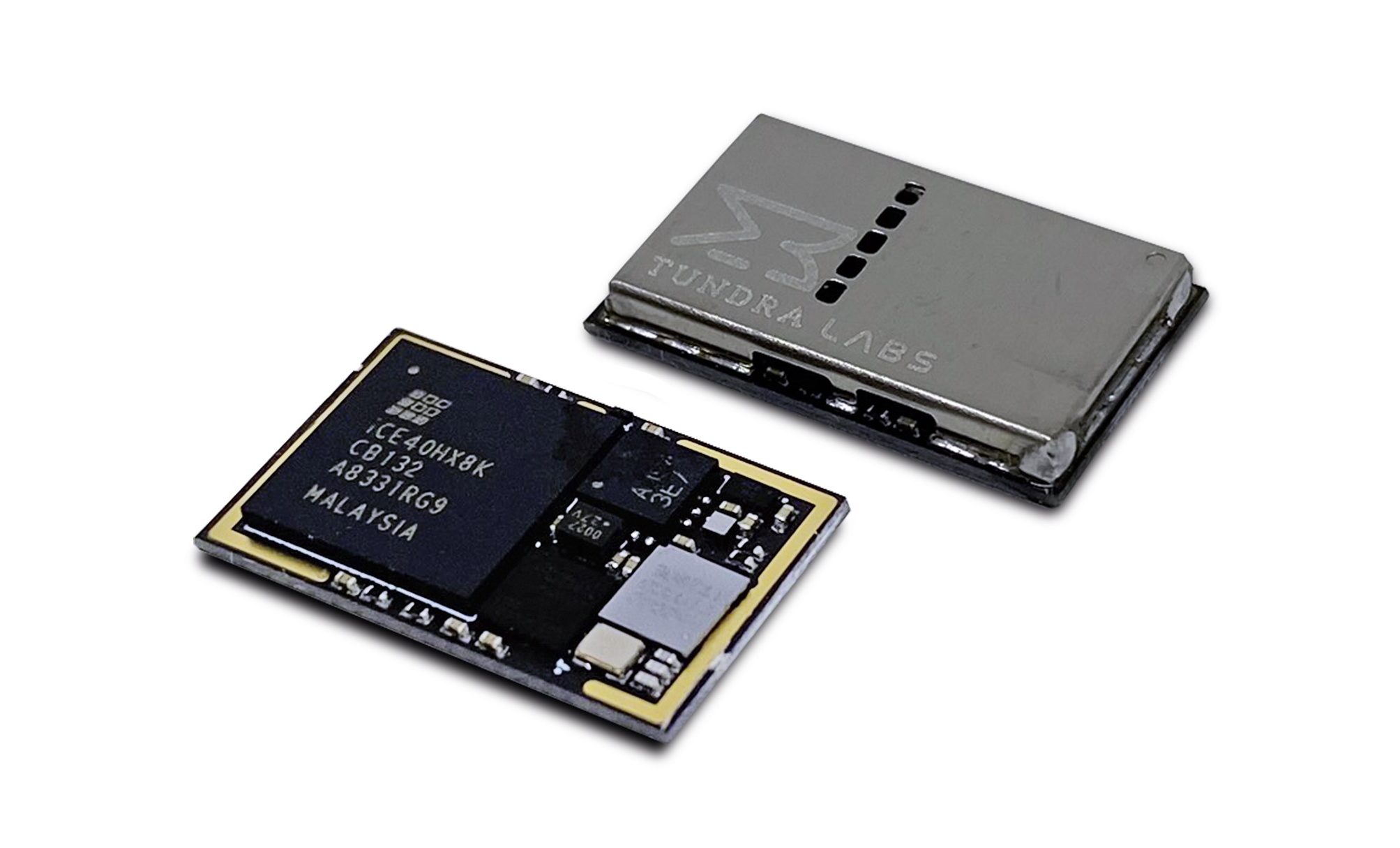
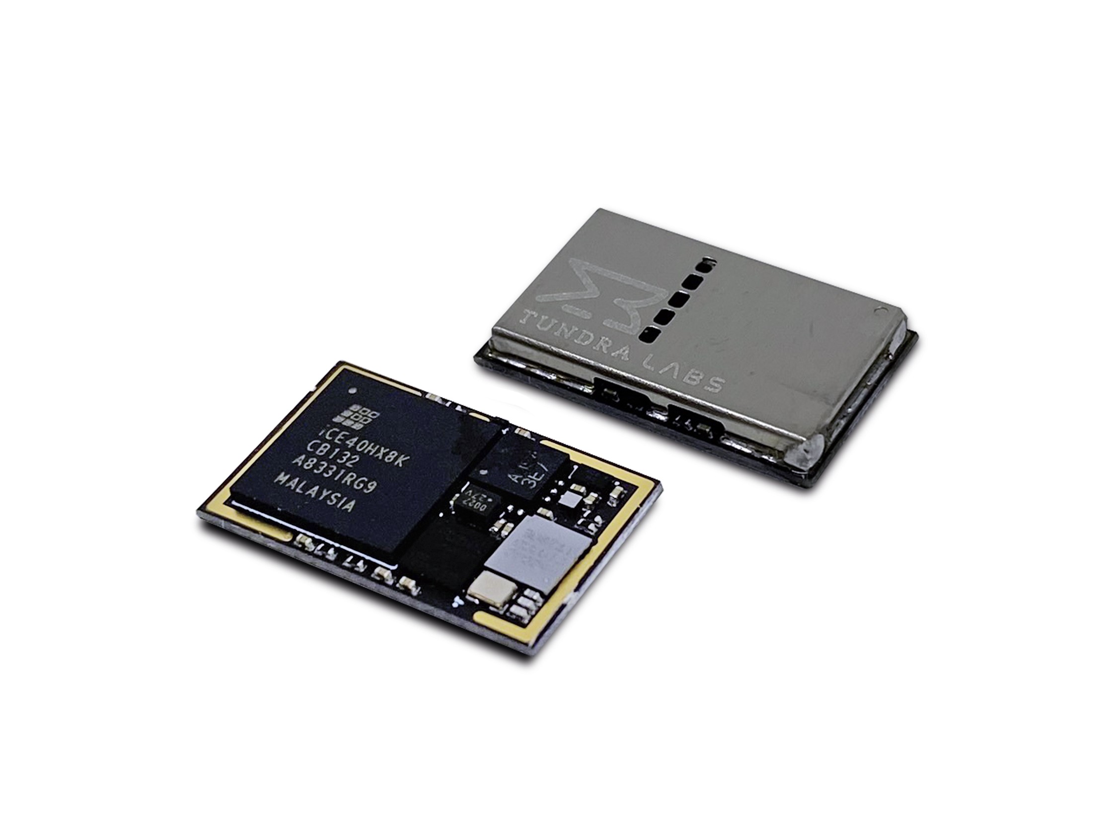
Nordic Semiconductor today announces that Tundra Labs, a Green Bay, WI-based technology company, has selected Nordic’s nRF52832 multiprotocol System-on-Chip (SoC) for its ‘TL448K6D-VR module’.
The TL448K6D-VR module assists developers to simplify and lower the cost of designing six-degrees-of-freedom (6DoF) tracked devices for Valve’s SteamVR gaming platform. The highly integrated module employs the 3.0 by 3.2mm Wafer Level Chip Scale Package (WL-CSP) version of the nRF52832 SoC to deliver an ultra compact 10 by 16.35 by 2.01mm System-in-Package (SiP) form factor weighing less than 1g. A compact and lightweight form factor is a key attribute for body-worn devices as well as head-mounted displays. In addition to virtual reality (VR) and augmented reality (AR), the module is suitable for computationally intensive tracking, eye tracking, sensor fusion, and motor control applications. The modules are produced in volume, programmed with the latest SteamVR firmware, and functionally tested.
The nRF52832 SoC’s RF performance and multiprotocol support were key requirements, particularly its backward compatibility with nRF24L Enhanced ShockBurst protocol
In addition to the 6DoF inertial measurement unit (IMU)—including a 3-axis accelerometer and 3-axis gyroscope—the module comprises the 64MHz, 32-bit Arm® Cortex® processor-based nRF52832 SoC, a second 120MHz Arm Cortex M4 processor, an 8k LUT field-programmable gate array (FPGA), two precision MEMs oscillators, and a crystal oscillator.
The nRF52832 SoC’s powerful Arm M4 processor is designed support the Floating Point (FP) and Digital Signal Processing (DSP) computations typical of high-end wireless applications. The SoC also integrates a 2.4GHz multiprotocol radio (supporting Bluetooth® 5, ANT™, and proprietary 2.4GHz RF protocol software) featuring -96dB RX sensitivity, with 512kB Flash memory and 64kB RAM. The SoC is supplied with Nordic’s S132 SoftDevice, a Bluetooth 5-certifed RF software protocol stack for building advanced Bluetooth LE applications. Nordic’s software architecture includes a clear separation between the RF protocol software and the developer’s application code, simplifying development and ensuring the SoftDevice doesn’t get corrupted when developing, compiling, testing, and verifying the application code. The S132 SoftDevice features Central, Peripheral, Broadcaster and Observer Bluetooth LE roles, and supports up to twenty connections.
“The nRF52832 SoC’s RF performance and multiprotocol support were key requirements, particularly its backward compatibility with [the proprietary 2.4GHz] nRF24L Enhanced ShockBurst protocol,” says Luke Beno, Founder of Tundra Labs. “The Nordic SoftDevice and nRF5 SDK [Software Development Kit] also provide useful flexibility for developers integrating TL448K6D-VR into their products.
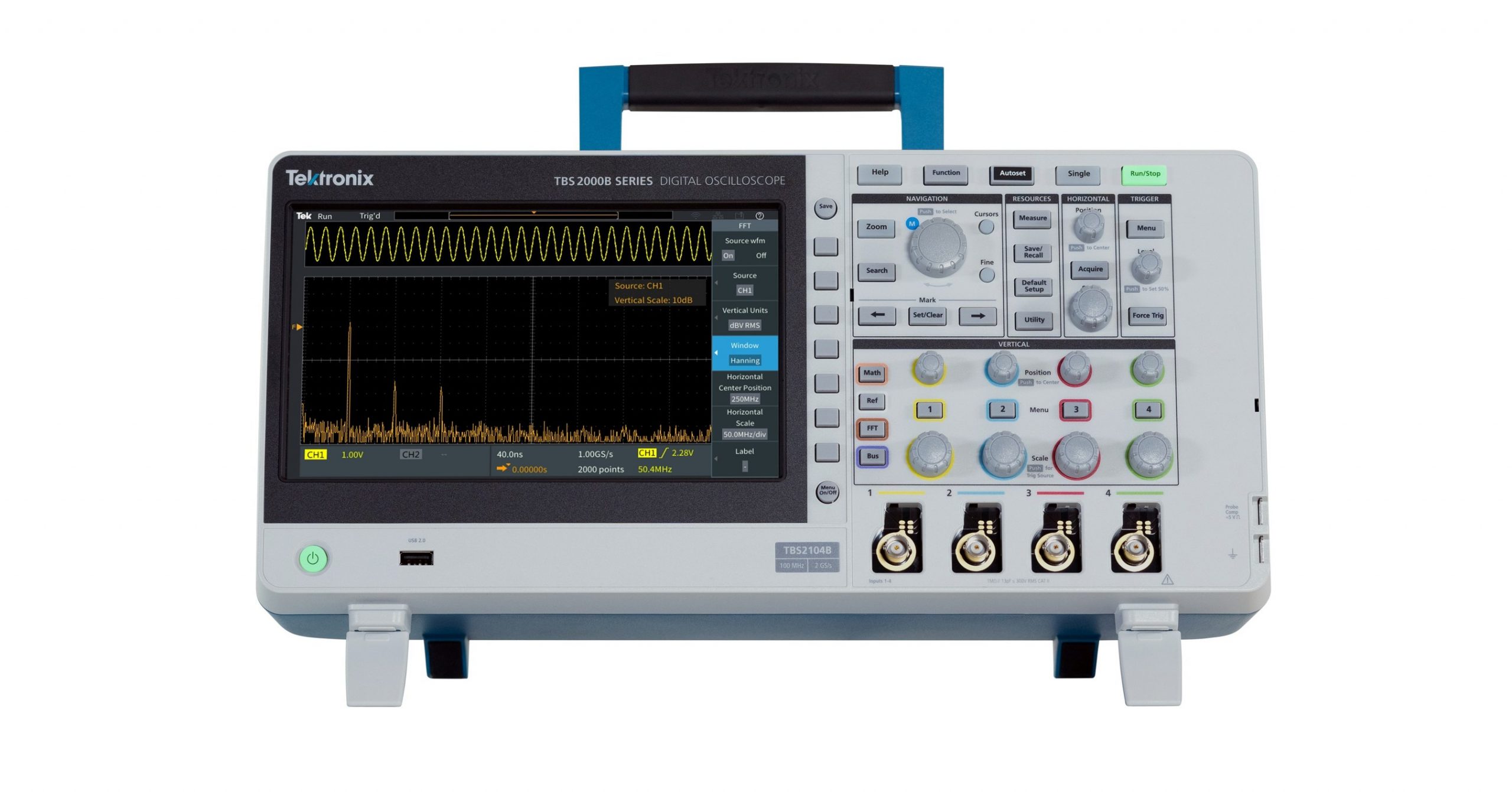
New TBS2000B Series of Digital Storage Oscilloscopes
Farnell is now stocking the Tektronix new entry-level TBS2000B Digital Storage Oscilloscope which offers easy-to-use controls, automated measurements and a large 9” display.
The cost-effective TBS2000B also provides exceptional performance and advanced debugging features. Farnel is offering a promotion of up to 15% off whilst stocks last.
The new Tektronix TBS2000B DSO builds on the performance and value of the earlier TBS2000 model. The TBS2000B series is a drop-in replacement for TBS2000 series oscilloscopes, featuring the same form factor and programmable interface.
Features include:
9-inch WVGA display with a 5-million-point record length and 2GS/s sample rate
32 automated measurements and on-waveform cursor readouts with search and mark features
TekVPI, Tektronix’s proprietary probe support interface, enabling wide application coverage using the latest active differential and current probes with automatic scaling and units. This is the industry’s only entry-level instrument featuring TekVPI. The TBS2000B also supports traditional passive BNC probes
Connectivity options including Wi-Fi support (via USB Wi-Fi dongle), 2 USB host ports, and 100-BaseT Ethernet
“Now, instead of using an SD card to store configuration files, I can simply send commands via the UART interface to the SSD from an external board and store/retrieve data without the extra code overhead.”
SD cards are used for storing information when logging data or retrieving files but with microcontrollers that have shorter RAM or a small number of GPIO pins, storing large amounts of data with an SD card while maintaining a small program can really be tough. There is the issue of extra software overhead and slow access time.
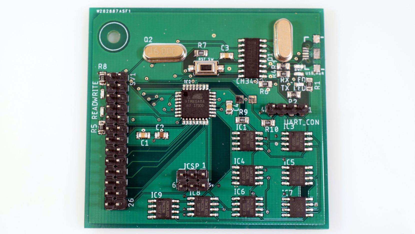
It was in a bid to find a suitable solution to this common problem that “Having11″ came about his new project: the design of an Arduino based SSD that uses an ATmega8 as a controller with several EEPROM chips.
Typically, an SSD is made up of a controller, set of flash chips, and DRAM that acts as a cache. The onboard controller takes in command through an interface, decodes it, and sets it ready to read or write data by the flash that is connected to the controller.
First, he had to decide on the kind of IC to use and the EEPROM seemed to fit perfectly well for the job. The chips, about 256 bytes each, are relatively cheap and easy to interface with. They operate at 5V and eliminate any form of logic level conversion between the EEPROM and the controller.
“As with most projects, it began with a simple sketch on paper. I laid out the rough locations of the components, such as groupi9ng the eight EEPROM chips together and placing the CH340G close to the ATmega8. Then I moved onto creating the schematics.”
He further assembled the board placing each component into their respective location, structured and organized the data, and made a protocol that consists of the host device that can send a command to the SSD for execution and give back a response.
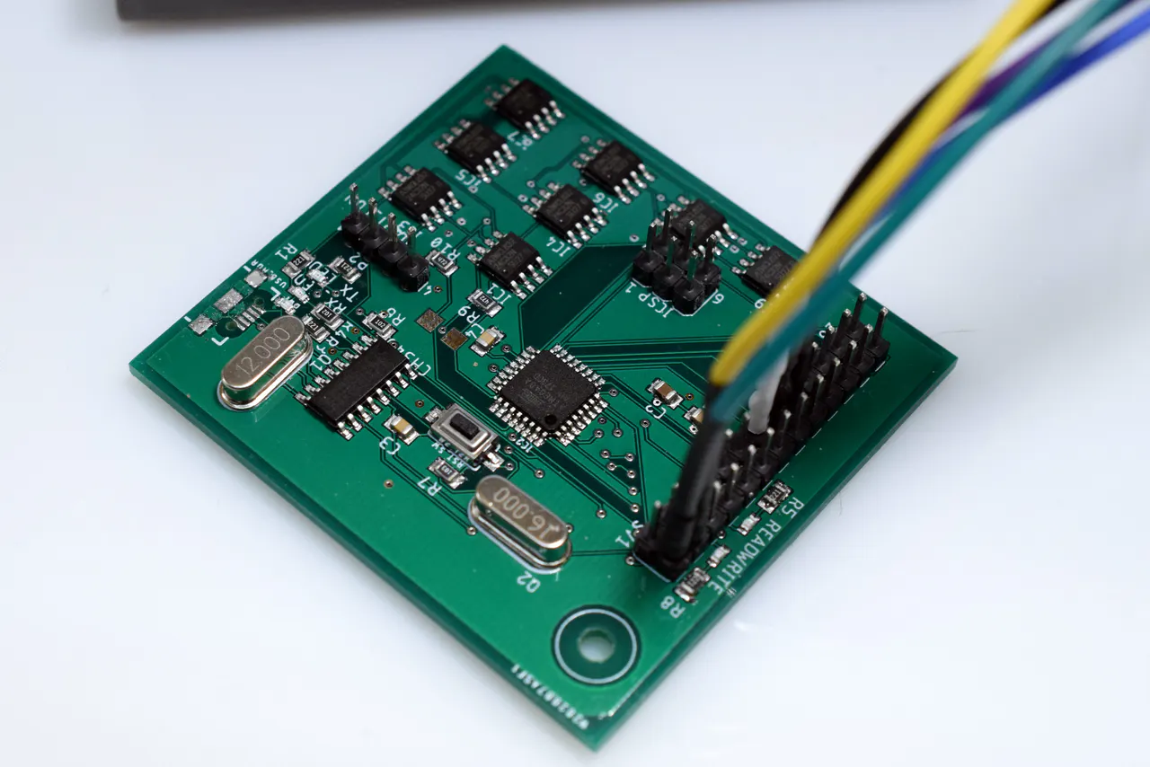
Meanwhile, he added that the board must have been programmed before commands can be sent through the USB or UART; its either you burn the Arduino bootloader into the ATmega8 or use the ICSP header to flash the chip through the SPI interface if you want to conserve space.
“Since I wanted the “SSD” to also communicate over USB, it was necessary to add a CH340G USB t UART converter. To test it out, I connected an FDTI USB to UART converter to my PC and the SSD. Then I wrote a simple python script that can send various commands and print out the corresponding data”.
Now, he has an SSD functioning conveniently as an SD card without extra software overhead.
More information about the project including a step-by-step guide to building the project can be found here