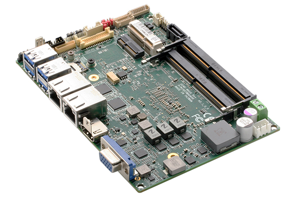
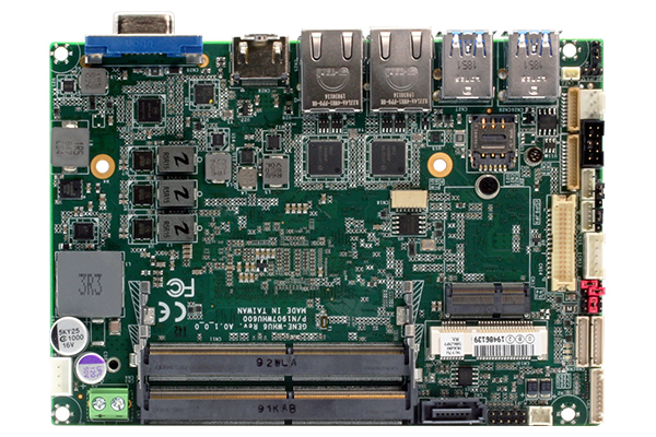
AAEON, an industry leader in compact embedded solutions, introduces the GENE-WHU6 subcompact board, powered by 8th Generation Intel® Core™ processors. Despite its compact size, the board offers full-sized functionality, able to deliver the flexibility of a desktop system in a compact form factor.
The GENE-WHU6 is built to provide performance beyond its size, powered by 8th Generation Intel® Core™ i3/i5/i7 and Celeron® processors (formerly Whiskey Lake) with greater processor performance than the previous generation. The GENE-WHU6 combines this processing power with up to 32GB of DDR4 SODIMM RAM for even greater computing performance.
Designed for full-sized functionality, the GENE-WHU6 provides a rich compliment of I/O features, including four USB 3.2 Gen 2 ports, two Gigabit Ethernet ports, and up to two COM ports supporting RS-232/422/485. The GENE-WHU6 also offers flexibility with display ports, featuring HDMI 2.0, VGA and LVDS. Users can also make use of the expandability of the GENE-WHU6 with a full-sized mPCIe slot, and two M.2 slots (one 2280 B Key and one 2230 E Key). The GENE-WHU6 supports AI accelerator modules, such as AAEON’s Kneron® KL520 NPU modules or the AI Core X family featuring Intel® Movidius® Myriad™ X.
The GENE-WHU6 is built to power embedded applications wherever it’s deployed. Designed for tough conditions, the GENE-WHU6 features wide voltage input (9-36V) as well as a wide operating temperature range (0°C to 60°C). Combined with its compact 3.5” form factor, the GENE-WHU6 can be deployed just about anywhere to power applications such as Smart Manufacturing and Intelligent Safety and Security.
“The GENE-WHU6 allows users the ability to deploy a compact solution that retains the functionality of larger machines,” said Menah Lin, Product Manager with AAEON’s Embedded Computing Division. “With greater flexibility and functionality than what other form factors support, the GENE-WHU6 delivers the power your embedded project requires.”
Features
Intel® Core™ i7/i5/i3/Celeron Processor SoC
Non-ECC DDR4 SODIMM Slot x 2, up to 32GB
LVDS/eDP x 1 (Default: LVDS), VGA x 1, HDMI 2.0 x 1
GbE x 2, SATA III x 1, DIO x 8bit
USB 3.2 Gen 2 x 4 (Up to Gen 2), RS-232/422/485 x 2
Full size mSATA/mPCIe Slot x 1 (With Nano-SIM)
M.2 2280 B key x 1, M.2 2230 E key x 1
Wide DC Input 9-36V (Optional: 12V Only)
With the GENE-WHU6, AAEON continues to offer their industry leading manufacturer support and OEM/ODM services. With these services, AAEON can provide customers with custom configurations and end-to-end project support.
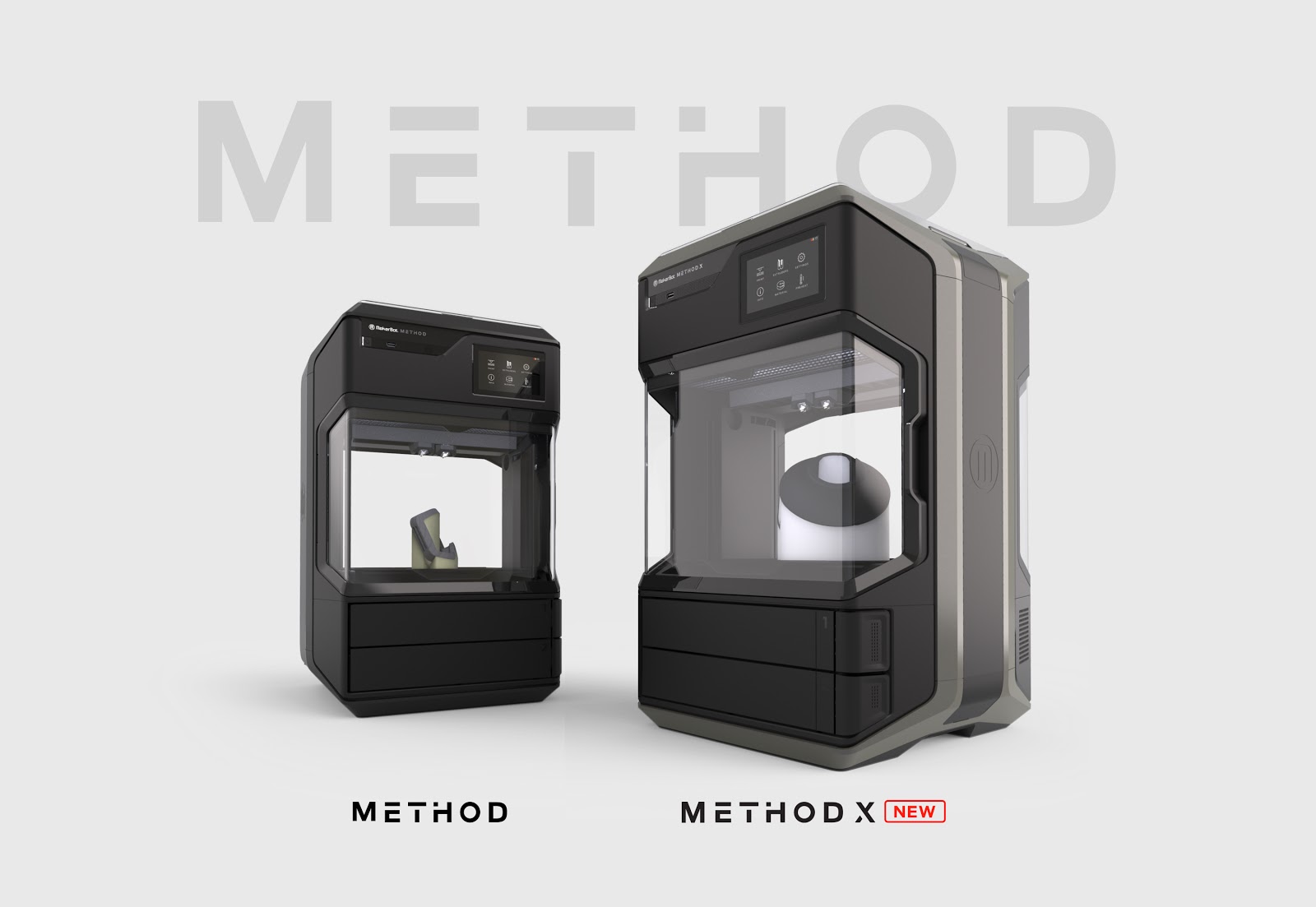
With companies impacted by the global health crisis, many are working from home – we are too. MakerBot has received several questions about how to set up a 3D printing studio at home. MakerBot’s own industrial designer – Felipe Casteñeda – will walk through the steps he goes through in his process including:
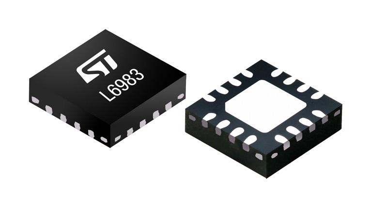
The L6983 is an easy to use synchronous monolithic step-down regulator capable of delivering up to 3 A DC to the load. The wide input voltage range makes the device suitable for a broad range of applications. The L6983 is based on a peak current mode architecture and is packaged in a QFN16 3×3 with internal compensation thus minimizing design complexity and size.
The L6983 is available both in low consumption mode (LCM) and low noise mode (LNM) versions. LCM maximizes the efficiency at light-load with controlled output voltage ripple so the device is suitable for battery-powered applications. LNM makes the switching frequency constant and minimizes the output voltage ripple for light load operations, meeting the specification for low noise sensitive applications. The L6983 allows the switching frequency to be selected in the 200 Hz – 2.2 MHz range with optional spread spectrum for improved EMC.
Key features
3.5 V to 38 V operating input voltage
Output voltage from 0.85 V to VIN
3.3 V and 5 V fixed output voltage versions
3 A DC output current
17 μA operating quiescent current
Internal compensation network
Two different versions: LCM for high efficiency at light loads and LNM for noise sensitive applications
2 μA shutdown current
Internal soft-start
Enable
Overvoltage protection
Output voltage sequencing
Thermal protection
200 kHz to 2.2 MHz programmable switching frequency. Stable with low ESR capacitor
Optional spread spectrum for improved EMC
Power Good
Synchronization to external clock for LNM devices
QFN16 package
The EN pin provides enable/disable function. The typical shutdown current is 2 µA when disabled. As soon as the EN pin is pulled up, the device is enabled and the internal 1.3 ms soft-start takes place. The L6983 features Power Good open collector that monitors the FB voltage. Pulse-by-pulse current sensing on both power elements implements an effective constant current protection and thermal shutdown prevents thermal run-away.
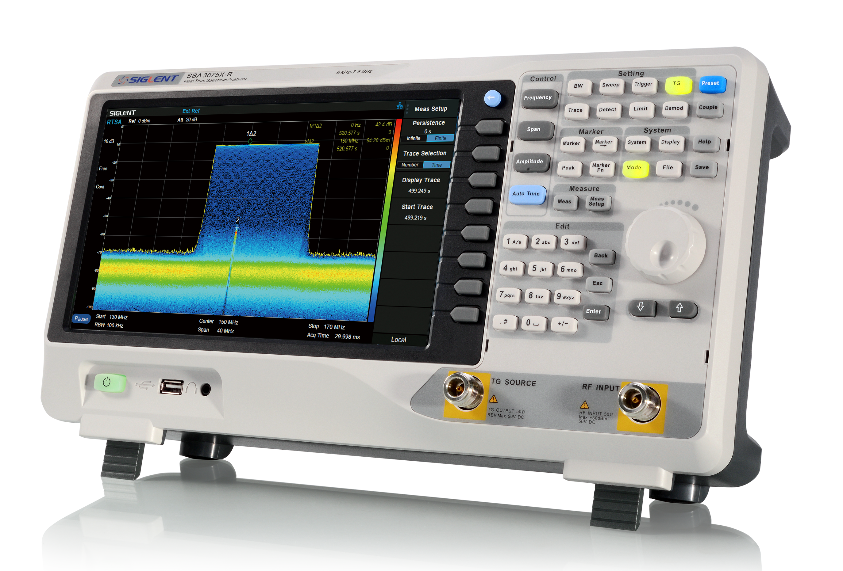
The SSA3075X-R extends the Siglent SSA3000X series to add real-time spectrum analysis capabilities for intermittent and frequency-hopping signals used in commercial communications and 5G applications.
Saelig Company, Inc. has introduced the SIGLENT SSA3000X-R Real-Time Spectrum Analyzers (RTSA) which are powerful and flexible tools for complex RF spectrum and signal analysis. With a capability of 40MHz analysis bandwidth and 7.2μs 100% probability of intercept (POI), the analyzers can provide multi-dimensional data displays, advanced triggering, and RF data capturing, to assist with modern RF spectrum challenges such as frequency hopping, channel conflicts, spectrum interference, etc. These RTSAs also contain a standard tracking generator for network analysis, optional wideband digital modulation analysis, and EMI measurement. The SSA3050X-R model has a frequency range of 9kHz to 5.0GHz, while the SSA3075X-R has a range of 9kHz to 7.5GHz. The built-in tracking generators operate from 100kHz to 5.0GHz and 100kHz to 7.5GHz respectively, and a preamplifier is included as standard. Control is made easy with a 10.1” multi-touch screen, with an external mouse and keyboard also supported. A remote control is also possible via an attached PC or web browser.
Many real-world signals such as modulated communications signals, spurious interference, and pulsed or frequency-hopping transmissions are sporadic, non-recurring, or even random. Using traditional spectrum analyzers, which steadily sweep through the active spectrum, these signals can easily be missed. Real-time spectrum analysis (RTSA) uses overlapping FFTs and high-speed memory to provide a 100% probability of intercept to detect even intermittent signals. Real-time bandwidth, the maximum frequency span of overlapping FFTs, is a critical parameter for an RTSA to allow detailed analysis of a signal’s spectrum.
The SSA3000X-R analyzers can also perform in a swept or a real-time mode. A modulation analysis mode is also available for AM/FM, ASK/FSK/PSK/MSK/QAM vector signal modulation analysis and EVM evaluation, as well as data recording to a PC. An EMI measurement mode allows for pre-compliance and other RF testing. Reflection measurement VSWR and return loss measurement with Q value calculation can be accomplished using an external reflection bridge or coupler.
Applications include: broadcast monitoring, evaluation, cellular site evaluation, IoT, WiFi, Bluetooth, R&D, education, production test & maintenance.
The Siglent SSA3075X-R is a powerful and flexible tool for RF signal and network analysis. With a frequency range up to 7.5 GHz, this analyzer delivers reliable automatic measurements and multiple modes of operation, with other optional functions also offered pre-compliance, research and development, education, production, and maintenance.
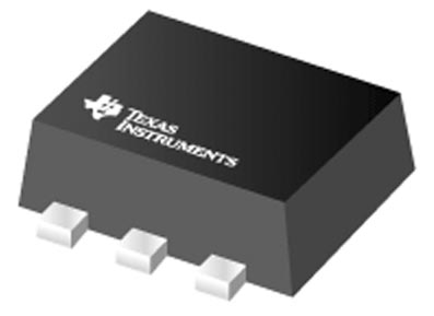
Texas Instruments has announced a new IC that is a part of family of ultra-low power, dual channel, resistor programmable temperature switches that enable protection and detection of system thermal events from –40 °C to 125 °C. The TMP390-Q1 offers independent overtemperature (hot) and undertemperature (cold) detection. The trip temperatures (TTRIP) and thermal hysteresis (THYST) options are programmed by two E96-series resistors (1% tolerance) on the SETA and SETB pins. Each resistor can range from 1.05 kΩ to 909 kΩ, representing one of 48 unique values.
The values of the resistor to ground on SETA input sets the TTRIP threshold of Channel A. The value of the resistor to ground on SETB input sets the TTRIP threshold of Channel B, as well as the THYST options of 5 °C, or 10 °C for both channels, to prevent undesired digital output switching. Resistors accuracy has no impact to TTRIP accuracy.
To enable customer board-level manufacturing, the TMP390-Q1 supports a trip test function where the digital outputs are activated by exercising the SETA or SETB pin.
Features
AEC-Q100 qualified with the following results:
Temperature grade 1: –40 °C to +125 °C operating temperature range
Resistor programmable temperature trip points and hysteresis options
Resistor tolerances contribute zero error
Hysteresis options: 5 °C, and 10 °C
Separate outputs for overtemperature or undertemperature detection
Channel A (overtemperature): +30 to +124 °C, 2 °C steps
Channel B (undertemperature): –50 to +25 °C, 5 °C steps
Accuracy without calibration
±1.5 °C (maximum) from 0 °C to +70 °C
±3.0 °C (maximum) from –40 °C to +125 °C
Ultra-low power consumption: 0.5 μA typical at 25 °C
Supply voltage: 1.62 to 5.5 V
Open-drain outputs
Trip test function enables in-system testing
Available in an SOT-563 (1.60-mm × 1.20-mm), 6-pin package
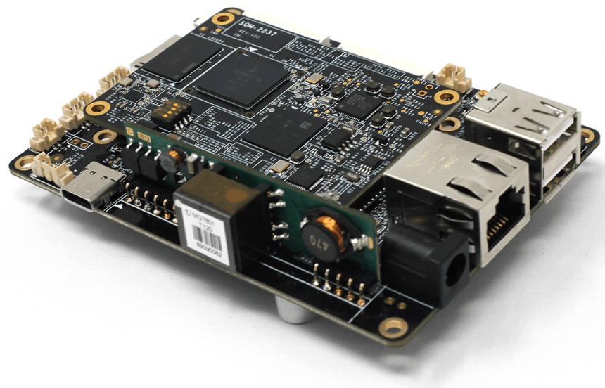
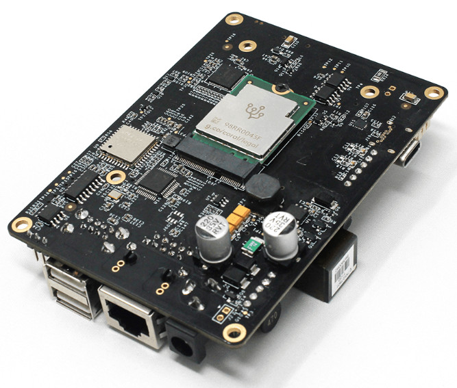
Targeted to satisfy diverse applications demanding a robust and compact computing POE edge AI embedded board for industrial machine learning, embedded vision and inferencing, the board is based on NXP application processors with 10+ year longevity support, built-in reliable communication interfaces like RS-485, RS-232 and M.2 slot for support of TPU, VPU accelerator modules like Google Coral Edge TPU and others.
PoE Power Module
Provides on-board Power over Ethernet (PoE) IEEE 802.3af standards power input via RJ45 Ethernet port for the board and system to make installing or large roll-out much simpler and cheaper
Single Point Touch Screen Connector
Integrates 4-lane MIPI DSI, dual Channel LVDS, RGB, power, backlight control and touch panel interface all in one FPC connector to give developers fast, convenient and simplified solutions for industrial and embedded POE touch panel PC applications.
The EMB-2237-AI POE edge AI embedded board takes the advantage of the latest NXP i.MX8MM application processors with scalable computing platforms and 15 years long life cycle support. It is designed to support Edge TPU, VPU machine learning accelerator modules and provides a solid base for your edge AI computer designs in areas like Human Machine Interface (HMI), voice control, machine vision, building automation and industrial AI.
On-board Voice Control Support
Built-in smart codec with dual-core DSP that runs algorithms for voice control, omni-directional spatial, noise suppression, and acoustic echo cancellation (AEC). Linux supports for Amazon AVS (Alexa Voice Service) Device SDK and Sensory TrulyHandsfree Wake Word Engine. Additional 8 channel digital audio/DMIC inputs (SAI5) for MIC array is also available via 40-pin expansion header.
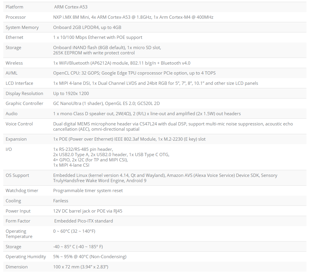
Specifications listed for the EMB-2237-AI include:
Touch Panel Development Kit
5”, 7” and 10″ touch panel development kits built on the EMB-2237-AI POE edge AI embedded board to help embedded software and application development and speed up time-to-market.
More information may be found on Estone Technology’s website.
If you need to import an electronic design from production files (Gerbers, drills, ipc-356 test point netlist) to any MCAD, you can use ZofzPCB.com’s new feature: STEP file export.
ZofzPCB loads Gerber files automatically, converts the board outline drawing into the bare PCB solid and PCB tracks into optimally constructed faces. Using IPC-356 bare board test point file, ZofzPCB can recreate footprint information and, with a very little help of the user, construct component 3D models, on the fly. The resulting STEP AP214 file is constructed as an assembly tree, containing additional information like component designators and, if a BOM file is also loaded, component names/values.STEP file export was the most often requested feature, by ZofzPCB users, it has now been implemented.
3D model of an assembled PCB, created by ZofzPCB, can be saved as a STEP AP214 file and loaded into any MCAD. ZofzPCB provides two distinct features.
As we have seen in the previous tutorial presenting the fundamental laws of circuit analysis, Kirchoff’s Circuit Laws (KCL) are a powerful and efficient tool to compute unknown voltages and currents in any circuit. However, KCL sometimes presents the inconvenience to be repetitive and is not the fastest way to analyze more complex circuits.
There are two methods based on KCL that simplify and make the analysis of circuits more efficient: the Nodal Voltage Analysis and the Mesh Current Analysis.
We separately present in this article both methods in two sections. In each section, a real example is given to illustrate how to perform these analyses.
Nodal Voltage Analysis
Presentation
The Nodal Voltage Analysis (NVA) is based on Kirchoff’s Current Law and is used to determine unknown voltages at the nodes of a circuit. It consists of a series of steps to follow, that are abstractly listed below:
Label the essential nodes of the circuit, essential nodes consist of nodes that are the junction between three or more branches.
Choose one of the nodes to be the reference of the circuit. In most cases, it is the bottom node.
Express the currents in the branches as a function of the voltages.
Write Kirchoff’s current law at each node other than the reference node.
Example
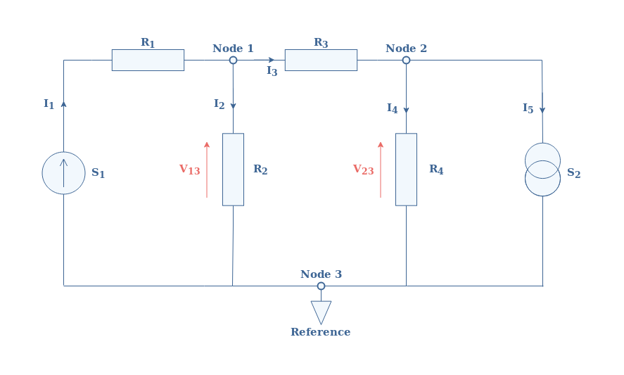
Consider the following electronic circuit presented in Figure 1 for which we will perform an NVA. For numerical applications, we take S1=10 V and S2=2 A; R1=1 Ω, R2=5 Ω, R3=2 Ω, and R4=10 Ω.
fig 1: Example of a circuit with labeled nodes, voltages, and currents
In this circuit, we already completed steps 1 and 2, the Node 3 has been chosen as the reference (ground) of the circuit, which is indicated with a grounding symbol.
According to step number 3, we can write each current I1, I2,…, I5 as a function of V12 and V13, the currents are computed by applying Ohm’s law to each branch:
I1=(10-V13)/R1
I2=V13/R2
I3=(V13-V23)/R3
I4=V23/R4
I5=-S2=-2 A
According to step 4, we write the Kirchoff’s current law at nodes 1 and 2:
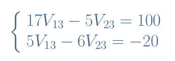
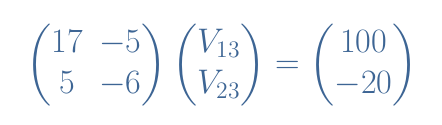
We obtain therefore a linear system of 2 equations with 2 unknown parameters that can be rewritten clearer by multiplying the lines with appropriate factors, arranging the terms and replacing the resistor and sources terms by their value:
This system can be rewritten as a matrix equation:
eq 1: Matrix equation of our example
This type of equation can easily be solved by hand or using a computer program such as MatLab, the solution is V13=9.1 V and V23=10.1 V.
Since every current is a function of these values, we can compute and list them:
I1=(10-9.1)/1=0.9 A
I2=9.1/5=1.8 A
I3=(9.1-10.1)/2=-0.5 A
I4=10.1/10=1 A
I5=-2 A
Mesh Current Analysis
Presentation
Another powerful method that simplifies the KCL such as the Nodal Voltage Analysis is presented in this section and known as the Mesh Current Analysis (MCA). Instead of focusing the analysis around the nodes such as presented for the previous method, we label the currents circulating in each mesh of the circuit. A mesh simply consists of a loop with no other internal loops in it.
We list below the following steps to perform an MCA:
Attribute and label currents on each mesh of the circuit. Usually, we choose the clockwise direction for positive currents.
Apply Kirchoff’s voltage law (KVL) for every mesh in the same direction as the currents previously stated.
Solve the loop equations that appear with the KVL analysis.
Compute the required current or voltage in the circuit thanks to the mesh currents.
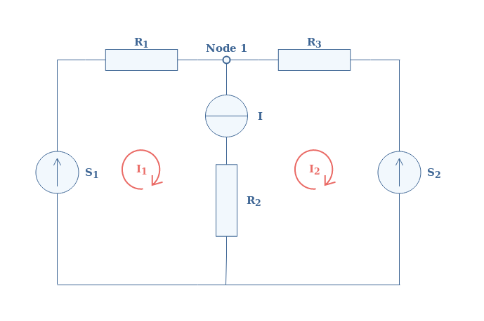
Example
Consider the following circuit illustrated in Figure 2 for which we will perform an MCA. The values of the different elements are given: S1=12 V and S2=6 V; R1=15 Ω, R2=2 Ω, and R3=12 Ω.
fig 2: Example of a circuit to perform an MCA on
Step number one has already been done in the circuit where the mesh currents are labeled with the red loop symbols.
As step number 2 suggests, we apply KVL for each mesh of the circuit:
Equation 1: -V1+I1×(R1+R2)-I2×R2=0
Equation 2: V2-I1×R2+I2×(R2+R3)=0
In our case, both mesh currents I1 and I2 are present across the resistor R2, in both equations we can see that the current across R2 is considered as the algebraic sum of I1 and I2.
In the following, we replace the parameters by their value, first of all, we express I1 as a function of I2 thanks to the first equation:
I1=(12+2×I2)/17
We substitute this term in Equation 2, which after redistributing the terms, leads to find I2=-1/3 A. We put this value in the expression of I1 to find I1=2/3 A.
Finally, we can give the required current I to drive the circuit I=I1-I2=1 A.
Conclusion
We have presented in this tutorial two methods based on the Kirchoff’s Circuit Laws called the Nodal Voltage Analysis (NVA) and the Mesh Current Analysis (MCA). These methods are more efficient to analyze circuits because they lead to the solution faster than KCL by reducing the amount of mathematics involved.
Each analysis consists of a series of steps to perform, the methods are presented separately at the beginning of their respective section.
Examples are also given in order to show how to analyze resistive circuits with these two methods. We can note that for reactive circuits with inductors and capacitors, the NVA or MCA analysis leads to a differential equation or a system of differential equations to be solved.
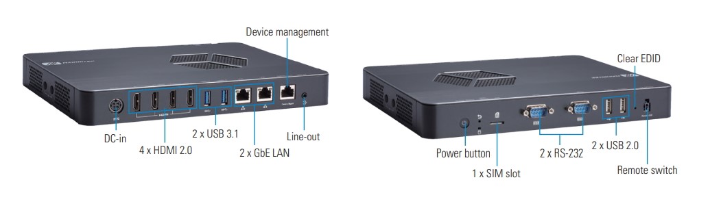
Axiomtek – a world-renowned leader relentlessly devoted in the research, development and manufacture of series of innovative and reliable industrial computer products of high efficiency – is pleased to release the DSP600-211, a 4K digital signage player powered by the onboard AMD Ryzen Embedded V1000 series processors. With superior graphics processing capabilities, EDID function, and feature-rich I/O, the wall-mountable DSP600-211 has four HDMI 2.0 ports supporting 4K for multi-display applications, such as video walls, digital menu boards, digital directory boards, interactive kiosks, and much more.
The DSP600-211 has scalable CPU options with the AMD Ryzen Embedded quad-core V1807B and V1605B. This powerful digital signage player has two DDR4-2400 SO-DIMM slots for up to 16GB of system memory. It also comes with one M.2 Key M 2280 for SATA storage and one M.2 Key M 2280 for NVMe storage. To meet the requirement of diverse applications, the outstanding media player has a rich I/O connectivity design. It offers two USB 3.1 ports, two USB 2.0 ports, two Gigabit Ethernet ports, one device management port, two RS-232, one Line-out, one SIM card slot and four antenna openings. Other features include one power switch, one reset switch, one Clear EDID, one remote switch, one HDD LED, and one VDC power input connector. It also has one M.2 Key E 2230 slot and one M.2 Key B for Wi-Fi, Bluetooth, or 4G LTE. The system supports 0°C to 45°C temperatures and offers 3 grms, 5~500Hz, random vibration. This compact system runs on Windows® 10 and Linux. It has been certified with CE and FCC Class A.
“Axiomtek’s DSP600-211 is designed for advertising and information dissemination in retail areas. To deliver immersive digital experience, this high-performance digital signage player provides four HDMI 2.0 ports which can display four images with up to 4K resolution. It offers flexible video wall configurations designed for applications including restaurant menu boards and digital displays in shopping malls. It is particularly suitable for 2×2 video wall,” said Ruei Tong, a product manager of Product PM Division at Axiomtek. ”Besides, the signage player supports Axiomtek’s exclusive Intelligent Remote Device Management (RDM) software which is specially designed for smart kiosk modules and digital signage players. It provides an ideal solution of high-efficiency and cost-saving in remote management.”
Digital signage players are widely used in many retail stores and shopping areas nowadays. The low power DSP600-211 is able to deliver stunningly rich and captivating visuals for enhancing the shopping experiences. This latest 4K digital signage player with four HDMI ports can easily support diverse advertising content in retail areas. The device is now available for purchase. For more product information or customization services, please visit our global website at www.axiomtek.com or contact one of our sales representatives at info@axiomtek.com.tw.
Advanced Features:
AMD Ryzen Embedded V1000 series
2 DDR4-2400 SO-DIMM for up to 16GB of memory
4 HDMI 2.0 with 4K resolution
4 USB, 2 GbE LAN
1 M.2 Key E 2230 for Wi-Fi/BT
2 M.2 Key M 2280 for storage
0°C to 45°C temperatures with AMD Ryzen Embedded quad-core V1605B
0°C to 40°C temperatures with AMD Ryzen Embedded quad-core V1807B
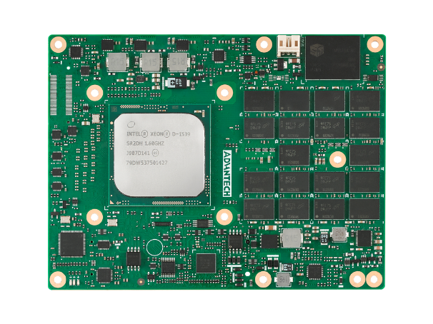
Advantech, a leading embedded computing solutions provider, is thrilled to announce the release of its new Type 7 COM Express Basic Module designed for a ruggedized applications, SOM-9590. The SOM-9590 provides an ideal foundation for new product designs due to its server-grade computing capability. With all solder-down design components, SOM-9590 meets the requirements of users requiring a reliable, high-performance solution. Target applications include railway transit, defence, mining, and communications requiring high computing power, data bandwidth, and the ability to work in harsh indoor and outdoor environments.
Integrated Server Performance and Enhanced Security Protection
SOM-9590 delivers powerful server-grade performance powered by Intel ® Xeon® processors and integrated with two 10GBASE-KR interfaces to help fulfill ever-increasing computing application demands in the area of edge networks. Users can take advantage of SOM-9590’s native 10GBASE-KR interface to design 10GbE carrier boards. TPM 2.0 is secured with 128bit capability (up to 256bit), a secure boot, and frozen BIOS to provide the best possible protection for user applications.
Reliability Guaranteed for Mission-Critical Applications
SOM-9590 features many design elements that fulfill the requirements of demanding environments. All components, including the processor, DDR4 memory, and SSD storage use onboard design, meet industrial-grade standards, and are IPC-A-6012 class 3 compliant in the hardware and layout phase. With certification from the MIL-STD-810G standard, SOM-9590 meets the exact demands of military applications. It’s capable of survival at vibration 7.7Grms (Method 514.7C-4), operating at a 50,000 feet altitude (Method 500.6 Procedure II), and it can perform in a -40 ~ 85°C temperature range. SOM-9590 has the IPC-A-610G Class 3 qualification—defined by IPC-org as fulfilling the highest quality product demands for critical applications.
SOM-9590 Features:
Powerful Performance Capability in Slim Body
Intel® Xeon® Processor D1539 with TDP 35W
iManager, WISE-PaaS and Embedded Software APIs
Low Module Profile 10.3 mm
Wider Ability in Bandwidth and Connectivity
Configurable PCIe Gen3 x16, x8 and 7 x1 expansion
Two 10GBASE-KR interfaces and 1000BASE-T
USB 3.0/ 2.0, SATA III, UART, GPIO and I2C
24/7 Non-Stop Reliability for Extreme Environments
Onboard ECC Memory and Storage SATA SSD
Certified by Miltary Standard MIL-STD-810G
Qualified by Manufacturing Process IPC-A-610G Class 3
Add-on Services
Conformal Coating Services
Advanced Cooling Solution – Quadro Flow Cooling System (QFCS)
Enhanced longevity of 7-15 yrs and beyond for long life military programs
SOM-9590D8AA-U0A1 is available for order. Please contact an Advantech sales office or visit the website (www.advantech.com) for more information.