DFI GHF51 is the smallest AMD Ryzen Embedded R1000 SBC in a RPi Size

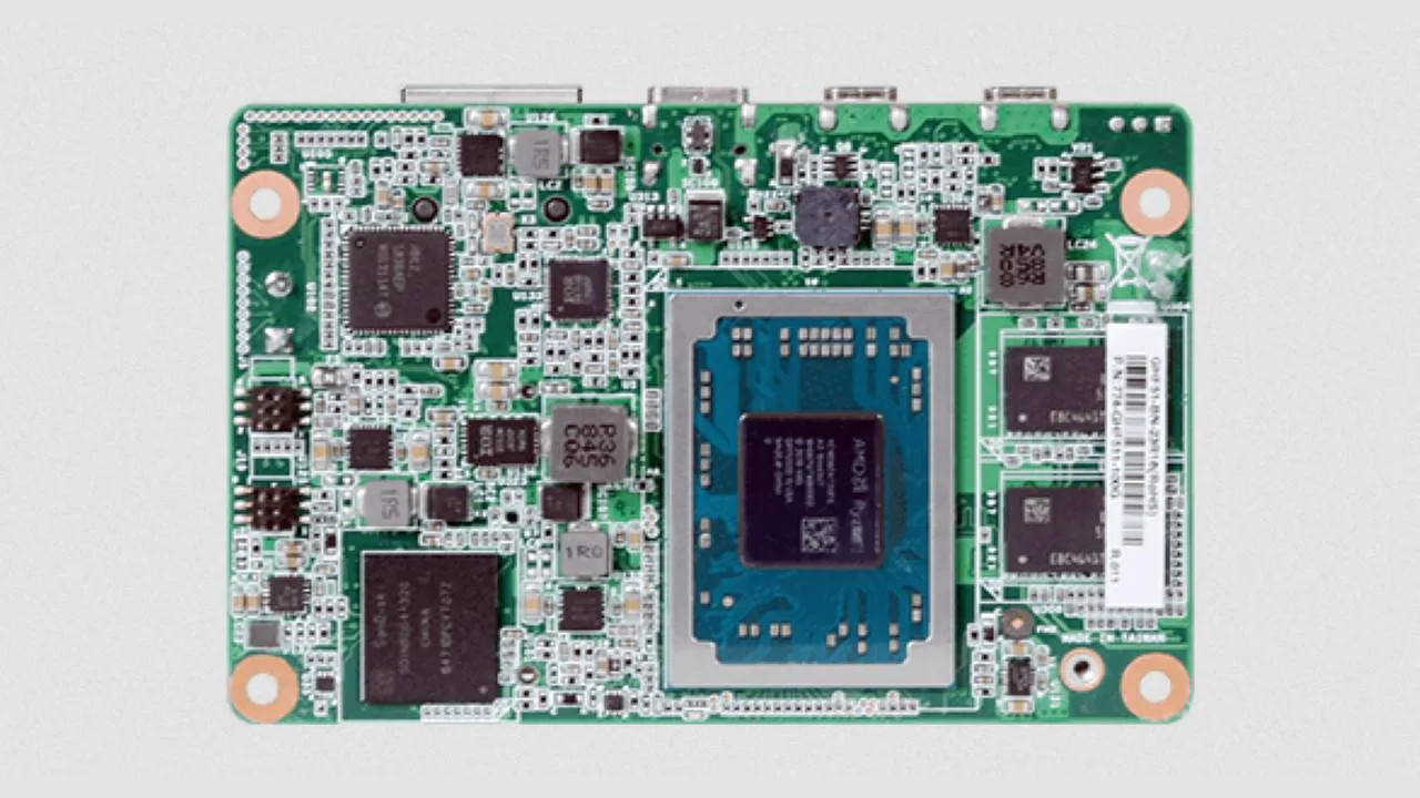
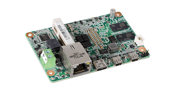
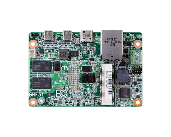
DFI, a global leader in the provision of various high-performance computing technology, has released the smallest AMD Ryzen Embedded R1000 Single Board Computer released so far called the DFI GHF51. We have seen a couple of AMD Ryzen Embedded boards with the likes of the Kontron 3.5″-SBC-VR1000, SAPPHIRE FS-FP5R, and a couple of others and all can be categorized as larger size boards as compared to the typical Raspberry Pi SBCs footprint standards. The DFI GHF51 changes all that measuring at 84 x 55 mm, is about the same size as the everyday Raspberry Pi.

DFI GHF51

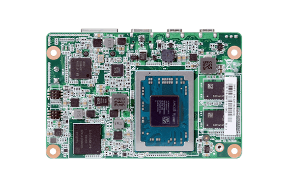
At the core of the DJI GHF51 is the dual-core, quad-threaded performance Ryzen R1000 SoC announced in 2019 by AMD. The GHF51 comes equipped with 2GB, and up to 8GB 3200MHz DDR4 RAM, also eMMC support is included from 16GB to 64GB onboard. Alongside the features mentioned, the board comes with a single GbE port with an option to select from Intel I211AT or I211IT controllers, USB3.1 Gen 2 type C port is available on the board with 2x micro-HDMI display ports capable of up to 4096 x 2160 resolution at 24Hz which all summarized the currently provided preliminary specifications released by DFI.

DFI GHF51

Some specifications

  • AMD Ryzen™ Embedded R1000 Series
  • Small form factor 1.8″ SBC for space-limited applications
  • Single Channel DDR4 Memory Down up to 2GB/4GB/8GB
  • HDMI 1.4 resolution supports up to 4096×2160 @ 60Hz
  • Expansion and Storage: 1 Mini PCIe, 1 SMBus
  • Rich I/O: 1 Intel GbE, 1 USB 3.1 Gen 2, 2 Micro HDMI
  • 10-Year CPU Life Cycle Support Until Q2′ 27 (Based on AMD Roadmap)

The board is expected to run operating systems booting via UEFI, such as Linux and Win 10 IoT. It comes with an operating temperature of  0 to 60°C and an optional-20 to 70°C operating temperatures as well. The board provides 8-bit DIO, SMBus, and a full-size mini-PCIe slot with PCIe Gen2 and USB 2.0 (or optional USB 3.1 Gen2). There’s also a watchdog, TPM 2.0 chip, and an RTC with coin cell battery.

DFI GHF51

There is no pricing information or board availability available for the Raspberry Pi size like the DJI GHF51 board on the product page. Still, according to LinuzGixmos, the SBC is expected to be available around Q3 2020, so more information will be expected to be available soon.

Dual-Channel Gate Driver for Enhancement Mode GaN Transistors

The uP1966A from uPI Semiconductor is designed to drive both high-side and low-side GaN FETs in half-bridge topologies. It integrates an internal bootstrap supply and UVLO. The uP1966A has split gate outputs that can operate to several MHz on both high and low side drive channels, providing the ability to adjust both turn-on and turn-off transition times independently.

A clamping circuit is used on the high side drive to keep unwanted transients from damaging GaN device gates. The uP1966A has two PWM inputs that independently control high side and low side drive signals.

Applications are expected to include:

  • Half-Bridge and Full-Bridge Converters
  • High Input Voltage Converters
  • Wireless Power

The uP1966A is available in a 12-pin WLCSP package that minimizes package inductance for improved high-speed operation. The operating temperature range is -40°C to +125°C. The uP1966A comes in a 1.6mm WLCSP 1.6 x 1.6-12B package.

Summary of Features

  • 4Ω/0.7Ω Pull-Down/Pull-Up Resistance
  • Fast Propagation Delays (15ns, Typical)
  • Fast Rise and Fall Times (8ns/4ns, Typical)
  • Adjustable Output for Turn-On/Turn-Off Ability
  • CMOS Compatible Input-Logic Threshold (Independent of Supply Voltage)
  • Under Voltage Lockout for Supply Input
  • WLCSP 1.6X1.6-12B Package
  • RoHS Compliant and Halogen Free

On The Web: uPI Semiconductor

Free Elektor Circuit: Cable & Conduit Locator

Apart from the risk of a (dangerous) electric shock and the near certainty of a very massive short circuit that is the consequence of drilling into a cable, the aftermath of this mishap is no fun either. In any case, the damaged cable has to be replaced – and that is already not nice when these are running neatly through conduit, but in other countries where the wires are often tidily hidden under the plaster work, this is a small catastrophe.

Prevention is better than cure, and that is why the better hobbyist makes use of a cable locator. But what to do on a rainy Sunday afternoon, when it is absolutely essential that a hole is drilled, but the DIY store is closed and you cannot quickly buy a cable locator? Then you build one yourself in a few minutes! Complicated it isn’t, as the schematic of Figure 1 proves.

read more

Analysis of buck converter efficiency

Tech note from Richtek on buck converter profiling. Link here

The synchronous buck circuit is wildly used to provide non-isolated power for low voltage and high current supply to system chip. To realize the power loss of synchronous buck converter and to improve efficiency is important for power designer. The application note introduces the analysis of buck converter efficiency and realizes major power component loss in synchronous buck converter.

Analysis of buck converter efficiency – [Link]

90V to 10V @ 500mA High Voltage DC-DC buck converter

This is a versatile tiny module that provides 10V/500mA from 90V DC input. It is a high voltage input DC-DC buck converter, based on LM5017 IC, which is a 100-V, 600-mA synchronous step-down regulator with integrated high side and low side MOSFETs. The constant on-time (COT) control scheme employed in the LM5017 requires no loop compensation, provides an excellent transient response, and enables very high step-down ratios. The ON-time varies inversely with the input voltage resulting in nearly constant frequency over the input voltage range. A high voltage startup regulator provides bias power for the internal operation of the IC and for integrated gate drivers. A peak current limit circuit protects against overload conditions. The under-voltage lockout (UVLO) circuit allows the input under-voltage threshold and hysteresis to be independently programmed. Other protection features include thermal shutdown and bias supply under-voltage lockout (VCC UVLO). Supply input range 13V to 90V, provides 10V/500mA, switching frequency 225 KHz. Adjustable output voltage possible by altering Resistor R6 and R8 value, refer data sheet. Under-Voltage lockout set to 12.4V.

Features

  • Wide 13V to 90V Input Range
  • Output 10V 500MA (Adjustable Output Voltage from 1.225 V)
  • Integrated 100-V High-Side, and Low-Side Switches
  • Constant On-Time Control
  • No Loop Compensation Required
  • Ultra-Fast Transient Response
  • Nearly Constant Operating Frequency
  • Intelligent Peak Current Limit
  • Precision 2% Feedback Reference
  • Frequency 225Khz (Adjustable to 1 MHz)
  • Adjustable Under voltage Lockout (UVLO) (Set to 12.4V)
  • Thermal Shutdown
  • PCB Dimensions 25.44 x 12.05 mm

Schematic

Parts List

Connections

Photos

LM5017 Datasheet

RS485 Shield For Arduino Nano

Arduino Nano RS485 shield will help you to transmit and receive serial data using the twisted pair RS485 network. The module provides half-duplex communication. LED D1 indicates receive data, D2 Transmit LED, J1 jumper is optional and not in use in this application. DI/RE connected to D2 of Arduino digital pin which enables Receiver Output /Driver Output. CN1 connecter supply input, CN2 3 pin screw terminal helps to connected twisted pair cable.  The unit can communicate over 4000 feet of 26AWG twisted-pair wire at 110 kHz into 120Ω loads.

Features

  • Supply 7-12V DC
  • D2 Transmit LED, D1 Receive LED
  • PCB Dimensions 40.46 x 17.98 mm

Schematic

Parts List

Photos

MAX485 Datasheet

SAM9X60-EK Evaluation Kit is ideal for evaluating SAM9X60 MPU

The SAM9X60-EK Evaluation Kit is ideal for evaluating and prototyping with the high performance, ultra-low power SAM9X60 ARM926EJ-S based microprocessor (MPU) running up to 600 MHz. The SAM9X60 MPU features powerful peripherals for connectivity and user interface applications, and offers advanced security functions.

Connectors and expansion headers allows for easy customization and quick access to leading edge embedded features such as Mikroelektronica click boards and Raspberry Pi expansion header.
The kit is supported by mainline Linux distribution as well as bare metal software frameworks and RTOS allowing you to easily get started with your development.
The kit includes an on-board Embedded Debugger, eliminating the need for external tools to program or debug.

Product Features

  • SAM9X60-V/DWB Microprocessor
    • 600 MHz ARM926EJ-S Core
    • 64 KB SRAM
    • LCD Controller
    • 2D Graphics Processor Unit
    • Dual 10/100 Ethernet
    • Dual CAN
    • Camera Interface
    • Thirtheen FLEXCOMs (USART, SPI and TWI)
    • 228-ball TFBGA
  • 256 MB DDR2 SDRAM
  • 512 MB NAND Flash
  • 8 MB QSPI Flash
  • One 10/100 Ethernet Port with Microchip KSZ8081 PHY
  • Three USB Ports
  • One SD Card Slot
  • LCD Connector
  • Dual CAN
  • Power Management IC, Microchip MIC2800
  • mikroBUS socket
  • Raspberry Pi expansion header
  • Embedded debugger
  • USB powered

more information: www.microchip.com

The ArduINA226 power monitor

ArduPicLab published the details on how to build a current, voltage and power datalogger with Arduino and the INA226 module:

In the past I have developed various projects of ammeters based on Hall effect current sensors such as the ACS712, or on High-Side Current-Sense Amplifiers such as the MAX4080SASA or made with operational amplifiers. All these systems have an analog output which must then be digitized. The INA226 sensor has a digital output and incorporates a 16-bit ADC for which a high accuracy and precision is obtained.

The ArduINA226 power monitor – [Link]

MCP4141 based digital potentiometer

Dilshan Jayakody has been working on an open-source hardware project MCP4141 based digital potentiometer, that is available on GitHub. MCP4141 and ATtiny13 based digital potentiometer to replace an existing 3 terminal analog potentiometers.

The main objective of this project is to create an experimental prototype of a digital potentiometer using Microchip’s MCP4141 IC. MCP4141 is available with end-to-end resistances of 5KΩ, 10KΩ, 50kΩ, and 100KΩ. This potentiometer-module can drive MCP4141 with any of the above mention resistances.

MCP4141 based digital potentiometer – [Link]

Mini ATtiny3217 development breakout board in DIL24

Albert van Dalen writes on avdweb about making a tiny development board in a DIL24 format containing a Microchip/Atmel ATtiny3217 microcontroller.

The Dily3217 is an Arduino compatible development board of 30x10mm, easy to integrate since it has a breadboard-friendly narrow DIL24 package. It is powered by the new ATtiny3217 and it has 21 I/O lines. It can be programmed with an external USB FTDI adapter. It has more or less the same functionality as the Arduino Uno.

The Dily3217 board is smaller than the ATmega328P chip itself, but it has more I/O pins, that’s crazy:

ATmega328P has 20 I/O pins
Dily3217 has 21 I/O pins

The ATtiny3217 has the most memory (32k/2048) and I/O pins (21) of the ATtiny series. And because of the QFN-24 package, the chip is extremely small. Note that, there is a trend that many new chips are only delivered in very small packages, with a pin spacing of about 0.5 mm.

Mini ATtiny3217 development breakout board in DIL24 – [Link]

TOP PCB Companies