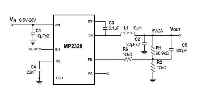
The MP2328 from Monolithic Power Systems is a fully-integrated high-frequency, step-down dc-dc converter with internal power MOSFETs and synchronous rectification. It offers a very compact solution to achieve a 2A continuous output current over a wide input range, with excellent load and line regulation. The MP2328 has synchronous-mode operation for high efficiency over wide output current-load range.
Constant On-Time control operation provides very fast transient response and easy loop design as well as very tight output regulation. Full protection features include SCP, OCP, UVP and thermal shutdown.
The MP2328 requires a minimal number of readily-available, standard, external components and is available in a space-saving SOT583 package.
Summary of Features and Benefits
Wide 4.5V-to-28V Operating Input Range
115mΩ/55mΩ Low-RDS(ON) Internal Power MOSFETs
160µA Quiescent Current
>92% Efficiency for 24V to 5V/2A Condition
Power Save Mode at Light Load
Fast Load Transient Response
430kHz Switching Frequency
Ton Extension for Improving Dropout
Programmable Soft-Start Time
Power Good Indication
Hiccup Mode OCP/OVP Protection
Thermal Shutdown Protection
Available in SOT583 Package
The MPL-AL Inductor Series Matches Best Performance
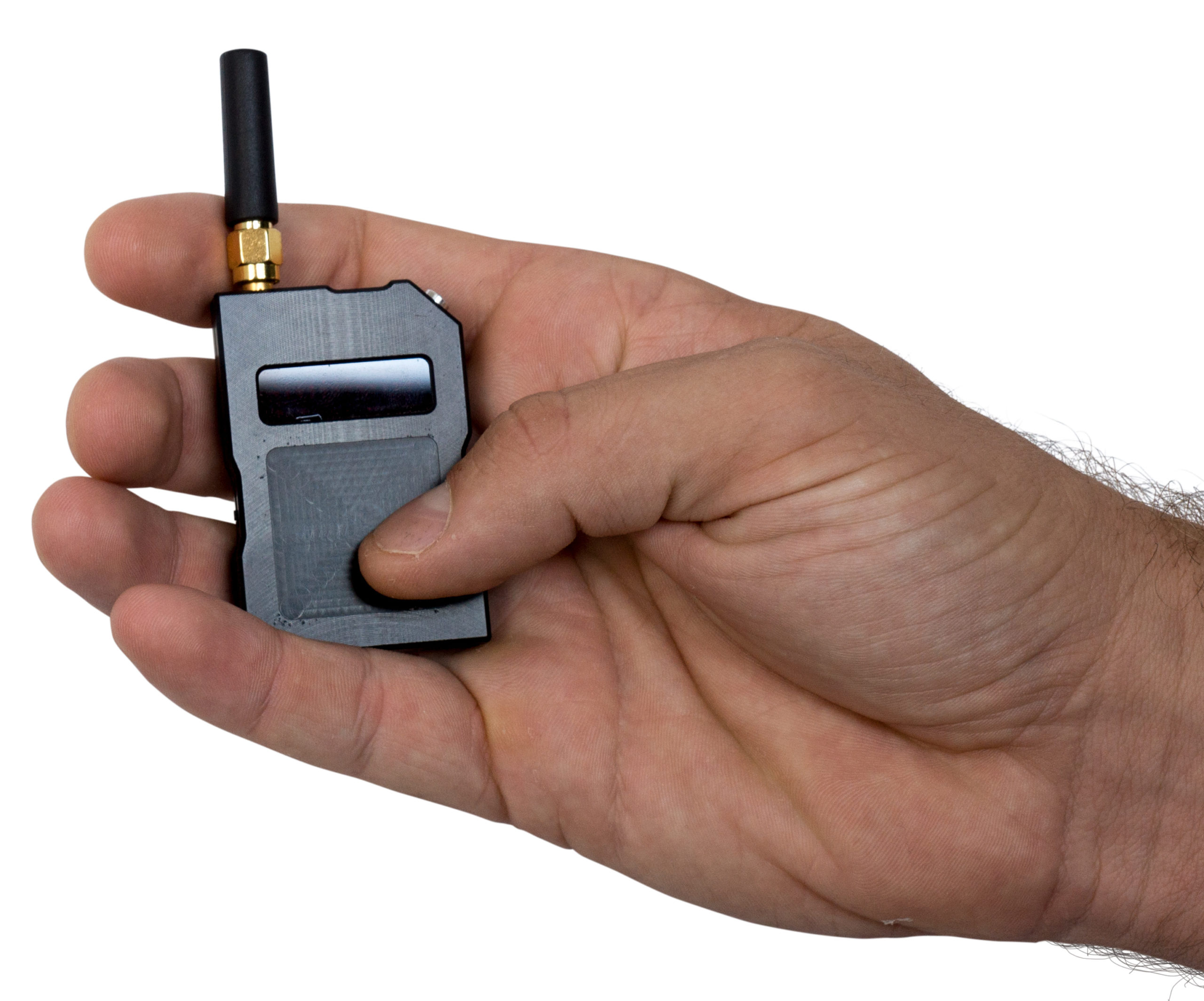
Counter-espionage device can be used to check for the latest technology hidden listening devices, covert cameras, and unauthorized mobile phone usage in location such as sensitive locations, and in vehicles to locate hidden GPS tracking devices.
Saelig Company, Inc. announces the availability of the Aaronia Bug Finder RF Monitoring Device, which helps in the detection of hidden audio and video bugs and transmitters. Covering a frequency range of 10MHz – 12GHz, the Bug Finder can tackle the latest innovations in bugging technology that use modulation methods such as FM, NFM, WFM, AM, PCM, PAM, DECT, WLAN, GSM, SS, SSB. Both the 12-point LED display and the Auto-Sense button make settings easy to navigate.
Designed for the ever increasing threat from more sophisticated and higher frequency RF devices, the Bug Finder produces a dynamic acoustic ‘blip’. As the finder gets closer to the RF signal’s source, the frequency of the blip intensifies. When the blip hits a constant note/tone, the blip interval can be reset, enabling the user to refine tracking the source. Included in the kit for focused tracking are two LogPer antennas (900 – 2500MHz and 2000 – 11000MHz) as well as two omnidirectional antennas (20 – 1500MHz and 900 – 12000MHz).
Many other signal detectors depend on a 9V battery as their power supply, limiting the ability to minimize the package size. But the Bug Finder’s metal case houses a 3.7V Lithium polymer battery that not only enables the finder to be considerably smaller and lighter than other alternatives but also allows concealed handheld operation for over 3 hours with a charging time of 1.5 hours.
Features
Frequency range: 10 MHz – 12,000 MHz
Input impedance: 50 Ohm
Display: 12-point LED display
Sound: Internal speaker or headset (2.5 mm headset jack/ mono)
The Aaronia Bug Finder RF Monitoring Device can be used to check for hidden listening devices, covert cameras, unauthorized mobile phone usage in location such as sensitive meeting rooms and offices, exam halls, hospitals, prisons, and in vehicles to locate hidden GPS tracking devices. Made in Germany by Aaronia AG, Europe’s award-winning, innovative manufacturer of RF site survey tools, handheld spectrum analyzers, antennas and EMC test probes, the Aaronia Bug Finder is available now from Saelig Company, Inc., technical distributor for Aaronia USA.
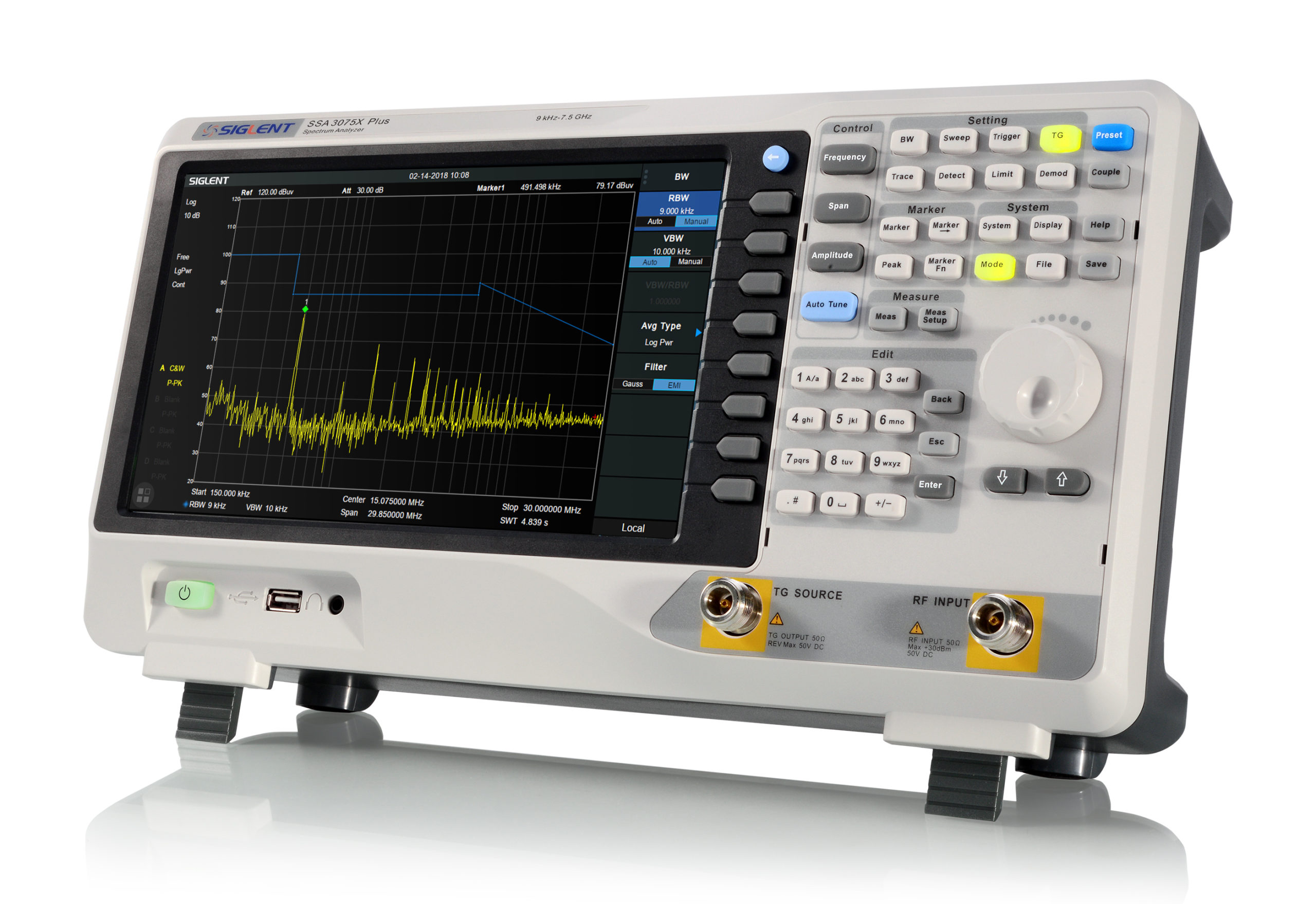
The SSA3075X-Plus extends the frequency range of the SSA3000X Plus series to meet the growing spectrum analysis needs for higher bandwidths in testing circuit designs for commercial communications bands and 5G applications.
Saelig Company. Inc. has introduced the SiglentSSA3075X Plus Spectrum Analyzer which extends the frequency range of the SSA3000X series to 7.5 GHz, which covers all commercial communications bands and provides instrumentation to meet the growing need for higher bandwidths in testing circuit designs for 5G applications. Convenient control is provided via a 10.1″ touch screen or traditional buttons and knobs. Connecting an external mouse or keyboard makes for a convenient, computer-like usage with an intuitive menu structure. An included web server also facilitates easy remote control from anywhere in the world.
Standard features and benefits include a -165 dBm/Hz Displayed Average Noise Level, 1 Hz Minimum Resolution Bandwidth (RBW), a preamplifier as standard, and a tracking generator. Available options include an Analog/Digital Signal Modulation Analysis Mode, a Reflection Measurement Kit for VSWR and Return Loss measurement, an EMI Pre-Compliance Test with Quasi-Peak Detector, and an Advanced Measurement Kit.
10.1” Multi-Touch Screen , Mouse and Keyboard support
Preamplifier standard
Tracking Generator standard
Analog/Digital Signal Modulation Analysis Mode (Opt.)
Reflection Measurement Kit (Opt.)
EMI Filter and Quasi-Peak Detector Kit(Opt.)
Advanced Measurement Kit (Opt.)
Web Browser Remote Control via PC or mobile terminals
The Siglent SSA3075X Plus Spectrum Analyzer is a powerful and flexible tool for RF signal and network analysis. With a frequency range up to 7.5 GHz, this analyzer delivers reliable automatic measurements and multiple modes of operation, with other optional functions also offered. Available now from Saelig Company, Inc., applications for the SSA3075X Plus include broadcast monitoring and evaluation, site surveying, EMI pre-compliance, research and development, education, production, and maintenance.
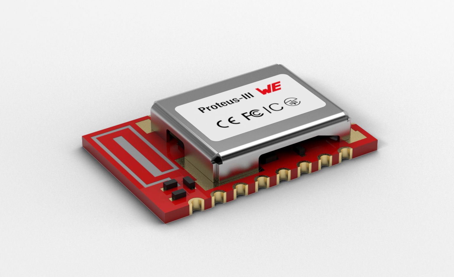
Würth Elektronik announced the Bluetooth Low Energy 5.1 module Proteus-III and the proprietary version Thyone-I. The modules, measuring only 8 × 12 × 2 mm, with integrated antenna, encryption technology and six configurable IO pins, are based on the Nordic Semiconductor nRF52840 chipset. They can be used for IoT and M2M applications, for example, to build radio-based maintenance interfaces and sensor networks. The WE-ProWare firmware from Würth Elektronik, which has been industrially proven over many years, makes the modules extremely versatile.
Proteus-III exploits the possibilities of the Bluetooth Low Energy 5.1 standard and even goes beyond them. With a payload of up to 964 bytes, the module offers four times the throughput of previous Bluetooth Low Energy modules. It can also establish connections in the newly introduced long range mode to transmit data over long distances. A special feature from Würth Elektronik: Proteus-III offers a good alternative to the SPP (Serial Port Profile) mode for serial data transmission, which is no longer included in the standard but is extremely useful for industrial applications. NFC wake-up and NFC pairing are prepared.
With the proprietary Thyone-I radio module, Würth Elektronik shows what is possible in the 2.4 GHz band: a range of up to 750 m and an end-to-end payload throughput of up to 400 kbps. A simple setup turns modules into repeaters in a mesh network, as required. WE-ProWare is an extremely versatile, easy-to-configure firmware with a lean and powerful radio protocol. If transmission standards are already specified in the application, Thyone-I can easily be converted to ZigBEE, Thread or Wirepas.
Proteus-III and Thyone-I are available from stock without a minimum order quantity. For both modules, Würth Elektronik offers evaluation boards, USB radio sticks with integrated radio module and very user-friendly manuals.
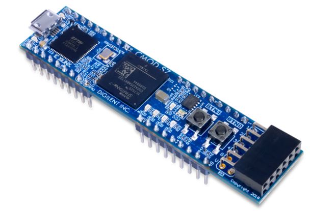
The Digilent Cmod S7 is a small, 48-pin DIP form factor board populated with 36 pins and built around a Xilinx Spartan-7 FPGA.
The Digilent Cmod S7 is a small, 48-pin DIP form factor board populated with 36 pins and built around a Xilinx Spartan-7 FPGA. The 32 FPGA digital I/O signals, 2 FPGA analog input signals, an external power input rail, and ground are routed to 100-mil-spaced through-hole pins, making the Cmod S7 well-suited for use with solderless breadboards. At just 0.7” by 3.05” inches, it can be loaded in a standard socket and used in embedded systems. The board also includes a programming ROM, clock source, USB programming and data transfer circuit, power supplies, LEDs, and buttons.
Features:
Xilinx Spartan-7 FPGA (XC7S25-1CSGA225C)
3,650 slices containing four 6-input LUTs and 8 flip-flops
1,620 Kbits of fast block RAM
Three clock management tile, each with a phase-locked loop and mixed-mode clock manager
80 DSP slices
Internal clock speeds exceeding 450 MHz
On-chip analog-to-digital converter (XADC)
Programmable over JTAG and Quad-SPI Flash
Memory
4 MB Quad-SPI Flash
Power
Powered from USB or 5V external supply connected to DIP pin 24 (micro USB cable NOT included)
USB
USB-JTAG programming circuitry
USB-UART bridge
Push-buttons and LEDs
2 Buttons
4 LEDs
1 RGB LED
Expansion Connectors
1 Pmod connector
8 total FPGA I/O
48-pin DIP form-factor headers
Contents
Cmod S7
Digilent cardboard packaging with protective foam inserts
iWave Systems, a global leader in embedded system and cutting edge solutions, has partnered with Crank Software Inc., to support vibrant and rich graphics representation on the powerful i.MX 8 series System on Modules and SBC boards.
Powered by the NXP i.MX8 application processors, the SOM and SBC are optimized for sophisticated real-time computing in embedded applications, and the Crank Software perfectly complements the high performing modules with out of the box GUI experience, enabling consumers to interact with our platform seamlessly.
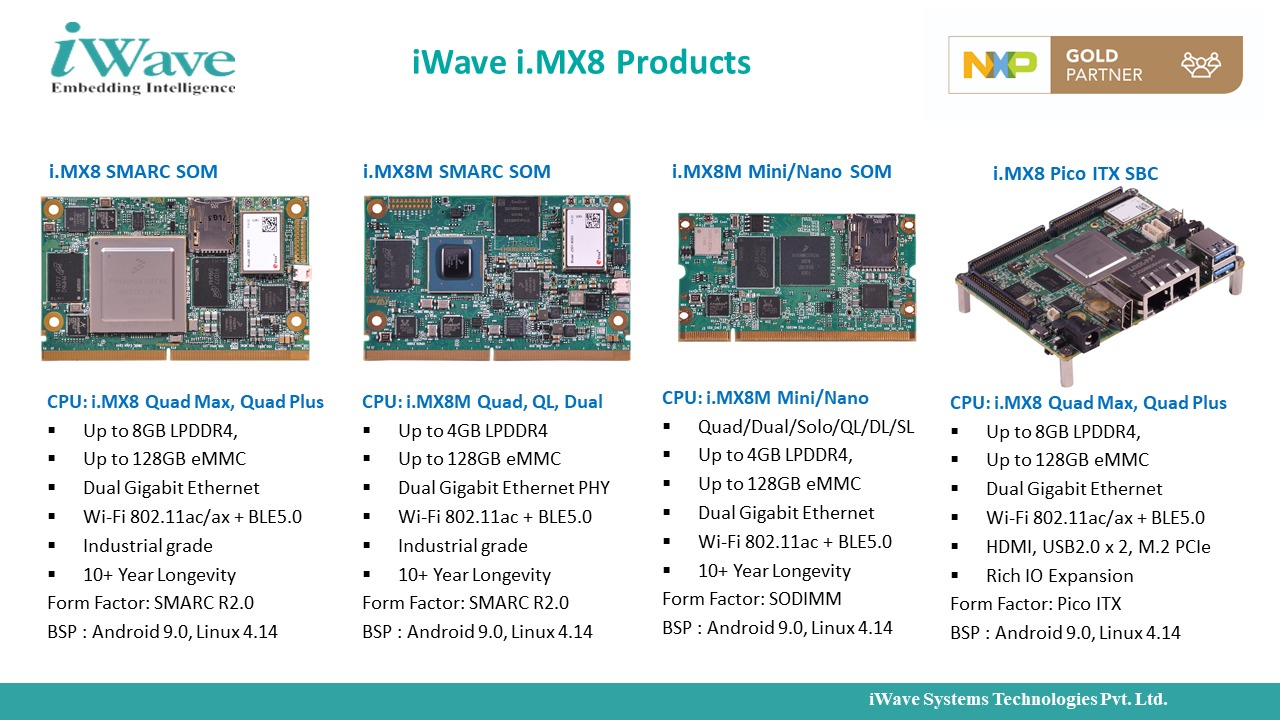
Here is an overview of iWave’s broad portfolio of i.MX8 Products:
Native to the i.MX 8QuadMax/QuadPlus SOM is an integrated high-performance Dual Vivante GC7000SXVX GPU and 4K H.265 capable VPU the Crank applications leverage to offer pixel-perfect 3D graphical acceleration on up to 4 x HD or one 4K display.
Crank has the following key features that make it well applicable for i.MX platforms:
Accessible directly within NXP MCUXpresso SDK
Wide support from FreeRTOS to QNX to Linux to Android OS
Built to leverage board features that drive performance
Consistent performance and reliability with both high- and low-power processors.
Media-rich user interface development – Graphics, Audio, Connectivity
Design, debug, deploy GUI without the need for programming
Import and re-upload files from Photoshop
Integrated animation & validation tools
Adaptable to technology stack changes (hardware & software & OS)
“iWave is committed to delivering high-quality solutions that will help our customers build products much quicker and with ease. The iWave i.MX 8 series SOM offers the ability to advance performance in integrated eCockpits, multi-camera, and multi-domain systems across industrial medical, automotive, and IIoT verticals. To fully enable advanced applications in customer products, collaboration with trusted partners such as Crank was integral to our go-to-market strategy, says Abdullah Khan, President, iWave Systems Technologies, India.
iWave systems and Crank Software collaboration will facilitate efficiency in design cycles, cost, and time to market for many customers who want to use the i.MX8 series processors. Our partnership with Crank Software will enable diverse graphical performance in various i.MX SOM/SBC products and also in various iWave HMI solutions.
Innovations enabled by winning combination of iWave platforms and Crank
Automotive:
The world is heading towards an increasingly autonomous and connected mobility. Take a glance at a modern vehicle today, and one would marvel at the amazing transformation that technology and digitalization have enabled, providing an amphitheatre-like experience – within the boundaries of a machine. From infotainment, navigation, instrument cluster to Heads up Display (HUD), boundless innovations are enriching user experience to never before seen dimension. Under the hood, iWave platforms and rich Crank GUI ensure dynamic performance, delivering rich and diverse functionality throughout the vehicle’s lifetime.
Medical:
Health care systems are evolving to newer standards of diagnosis and patient care. Continuous monitoring using connected technology allows patients to conveniently interact with their health provider 24/7, accelerating early diagnosis, and better recording of health data. Emerging technologies are enabling advanced use cases to the point of performing medical operations remotely on patients. Such innovative concepts require efficient and sophisticated computing platforms such as i.MX8 and rich embedded GUI that facilitates seamless interaction, real-time intelligence, and flexibility in supercritical medical applications.
IoT Automation:
Be it production centre or home, imagine the possibilities of having complete control over your assets even when you are away. Remote monitoring via automation systems ensures maximum throughput, interoperability in addition to cost and energy savings. iWave SOM platform and Crank GUI work in tandem to offer state of the art interactive platform to monitor assets and improve resource efficiency.
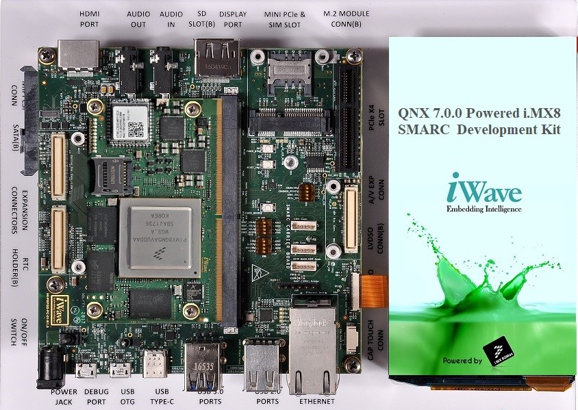
Crank Story Board demo on iWave i.MX 8QM/QP SMARC module:
Multiple display options including 4K HDMI, video input, CAN ports
Multiple PCIe devices, SATA, USB3.0, Serial interfaces and Audio.
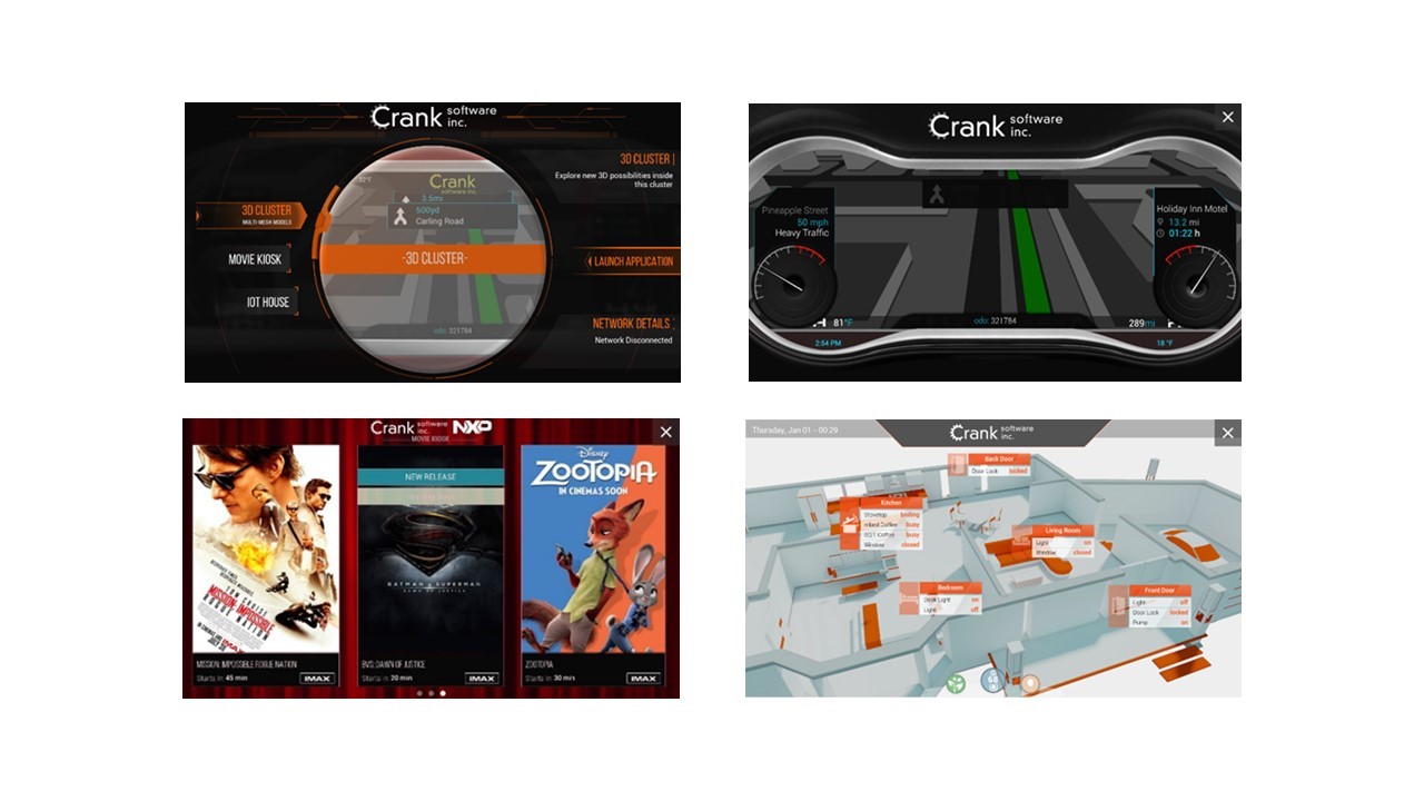
Following are few snapshots of the Crank Application running on QNX RTOS in iWave’s i.MX 8QM SMARC development board;
GUI development on iWave SOMs and SBCs
Crank software enables a no programming framework that allows designers to easily generate stunning graphical images and animations by directly importing the GUI designs from software such as Adobe Photoshop and Adobe Sketch. Crank development tools instantly creates rich GUI pages along with interface routines and customized GUI images for various end applications requirements.
The resulting source code is cross-compiled to generate programmable binaries and copied to the target board using a simple USB / Ethernet interface. And that’s it; the GUI is now ready for use in the SOM platform in just a few minutes!!
Advantages of using iWave Platforms:
10+ years long term product longevity
Technical support
Pre-integrated libraries to run CRANK applications with iWave BSP
Recognized skills and know-how with wide-ranging OS and RTOS
Turnkey hardware, software services, and manufacturing support
iWave is NXP Proven Gold Partner and worked with all i.MX parts
iWave extends service in customizing BSP for developing the Crank GUI and contribute to bringing the applications to life quickly and affordably to various i.MX8 family such as i.MX8, i.MX8M, i.MX8X and i.MX8M mini/nano.
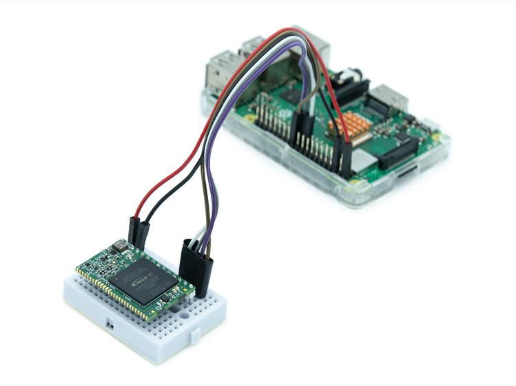
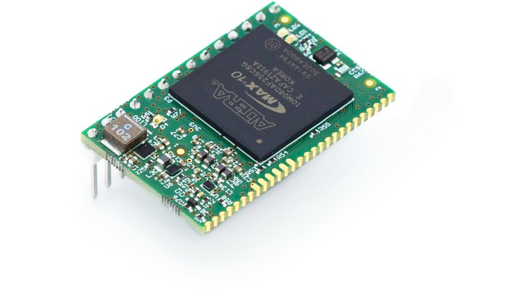
Kryptor is a (Field Programmable Gate Array) FPGA board that comes with the different functionalities needed to aid data encryption. The board is an HSM (Hardware Security Module) that protects and manages digital keys for strong authentication. The board has been designed to support any processor that supports serial interfaces; therefore, it is excellent for makers boards like Arduino and Raspberry Pi.
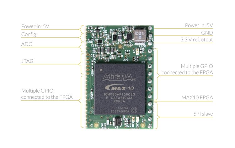
Kryptor is powered by a single compact Intel/Altera MAX10 FPGA chip with 100 MHz operating frequency, 1376 Kb flash memory, and a 378 Kb RAM in total. It can be connected via a 2.54mm pin header, which is excellent for a standard breadboard. Jumper cables are also provided; there are four cables for SPI, 1 for 5V and 1 for GND. The controller boards can also be connected to Kryptor using 12C, SPI, and UART.
Kryptor FPGA The One-Chip Hardware Security Module (HSM) and MAX10 FPGA Dev Board
Technical Specifications include:
FPGA: Intel/Altera MAX10 8K LE (10M08DAF256C8G)
Dimensions: 23×35 mm
Internal flash: 1376 Kb
Internal RAM: 378 Kb total
GPIO: 250 available from the FPGA (fewer accessible via the board)
Operating frequency: 100 MHz
Control: API / encrypted Command Line Interface
Duplication protection: Anti-piracy duplication protection via chip ID
Encryption speed: symmetric encryption speed up to 108 Mbps on a single core (SPI link speed capped at 2 Mbps.
The RAM and flash memory circuits are enclosed within the FPGA to help as it offers a safer architecture compared to the usage of external chips that have to be physically secured. There is also a free and easy-to-use API for Linux, which is a fantastic feature to help beginners figure out Kryptor quickly. An Arduino library is also provided.
Kryptor users have the option of downloading the HSM soft-core at no cost from Skudo. It comes with instructions on how to flash it into their own FPGA Krypto boards. The HSM soft-core can be uploaded at any time; therefore, owners are free to use the Kryptor board with their own soft-core and make use of the secure and professional MAX10 FPGA.
True Random Number Generator (TRNG): running in dedicated Hardware (FPGA)
Expandable: The FPGA is expandable with external software functions executed inside the chip
Optional functions: Other functions like RSA, AES256, and Keccak can be integrated if needed for legacy applications
Kryptor eliminates the need for software-based encryption functionalities by replacing them with real hardware ones and also avoids using any Operating System (OS) – reducing the options for potential surface attacks (virus, malware injection, and bug exploits).
Kryptor is currently on the course for crowdfunding on Crowd Supply. More information is available on the page.
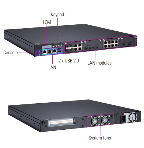
Axiomtek – a world-renowned leader relentlessly devoted in the research, development and manufacture of series of innovative and reliable industrial computer products of high efficiency – is pleased to release the NA591, an advanced 1U rackmount network appliance platform with a maximum of thirty-four LAN ports. This high-performance network appliance system is powered by the Intel® Xeon® E-2200 and 9th/8th gen Intel® Core™ i7/i5/i3 (Coffee Lake/Coffee Lake Reflash) processors with the Intel® C246 chipset. The NA591 comes with four expandable LAN module slots that support 1GbE/10GbE/25GbE/40GbE/Fiber/Copper/LAN Bypass interfaces, greatly enhancing its flexibility and scalability. This scalable 1U network appliance platform delivers security, stability and reliability for VPN, firewall, network bandwidth controller, WAN accelerator and surveillance system applications.
“Axiomtek’s NA591 features optimized computing power and virtualization capacity in a compact 1U form factor. It provides stable, reliable and non-stop network operation for a wide range of applications in industrial cybersecurity,” said Bruce Cheng, a product manager of Product PM Division at Axiomtek. “This outstanding network security appliance features Intelligent Platform Management Interface (IPMI) to allow administrators to monitor system health and manage systems. Trusted Platform Module (TPM) is supported to bolster hardware-based data protection. Moreover, it features latch-type LAN Bypass functions for fail-over option as well as featuring BIOS console redirection. The NA591 is an ideal platform for network security, cloud computing and data centers applications.”
The NA591 is equipped with four DDR4-2666 U-DIMM slots with a memory capacity of up to 128GB. It also offers two 2.5” SATA HDD and one mSATA for adequate storage. The rackmount network communication platform has two USB 2.0 ports, one serial console port and one VGA port. To ensure reliable operation, the well-developed NA591 supports watchdog timer featuring 255 stepping for system reset and 8 stepping for LAN Bypass. The high-performance network appliance platform is compatible with Linux operating systems.
Advanced Features:
LGA1151 socket 9th/8th gen Intel® Core™ i7/i5/i3 & Xeon® E-2200 processor (Coffee Lake/Coffee Lake Reflash)
4 DDR4-2666 U-DIMM for up to 128GB memory
up to 34 GbE LAN ports
4 expandable LAN modules supporting 1GbE/10GbE/25GbE/40GbE/Fiber/Copper/Bypass for optional
Supports 1U redundant power supply for optional
Supports IPMI and TPM for optional
Suitable for network security, cloud computing and data centers applications.
Axiomtek’s NA591 is now available for purchase. For more product information or customization services, please visit our global website at www.axiomtek.com or contact one of our sales representatives at info@axiomtek.com.tw.
It is in the late 30’s that an American engineer named Hendrick Wade Bode designs a famous representation to study AC circuits in the frequency domain. These graphs are still nowadays very useful in electronics and automatism and are called Bode diagrams.
In this tutorial, we will give every necessary step in order to represent and read Bode diagrams.
First of all, we present every necessary concept that needs to be detailed previously. We will, therefore, give a recap about the notions of the transfer function, gain, and phase.
The following of the article consists of understanding how to read these diagrams, which provides much information about an unknown circuit.
The last section shows how to plot the diagrams of some of the most common electronic circuits. This process is useful to share the information in a compact form of a specific circuit in a manual user for example.
Definitions
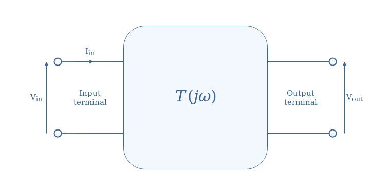
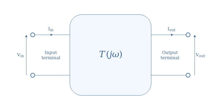
The transfer function is the fundamental notion to understand before talking about Bode diagrams. Consider any linear electronic circuit defined by its transfer function T(jω) and represented in Figure 1 by a box, with one input and one output terminal:
fig 1: Quadripole representation of a linear electronic circuit
The transfer function is defined by Vout=T(jω)×Vin with Vin=|Vin|ejωt. Sometimes, we can note p or s=jω which is known as the Laplace variable.
From this transfer function, two important parameters can be computed. The first one is the gain/amplitude (G), which is found by taking the norm of this complex function: G=|T(jω)|. In order to plot Bode diagrams, it is the gain in decibels (GdB) that is considered: GdB=20log(G).
A gain GdB=0 indicates that the norms of the input and output are equal |Vin|=|Vout|, this is called a unitary gain. When GdB tends to infinite negative values, no output is observed despite the presence of an input.
The second important parameter is the phase difference (ΔΦ) between the input and output. This phase difference is given by the argument of the transfer function: arg(T(jω))=ΔΦ. This equality comes from the fact that if we consider a ratio of complex numbers z1/z2, the argument is given by the differences of the arguments of the numerator and denominator, which proves the previous formula: arg(z1/z2)=arg(z1)-arg(z2).
Presentation of Bode diagrams
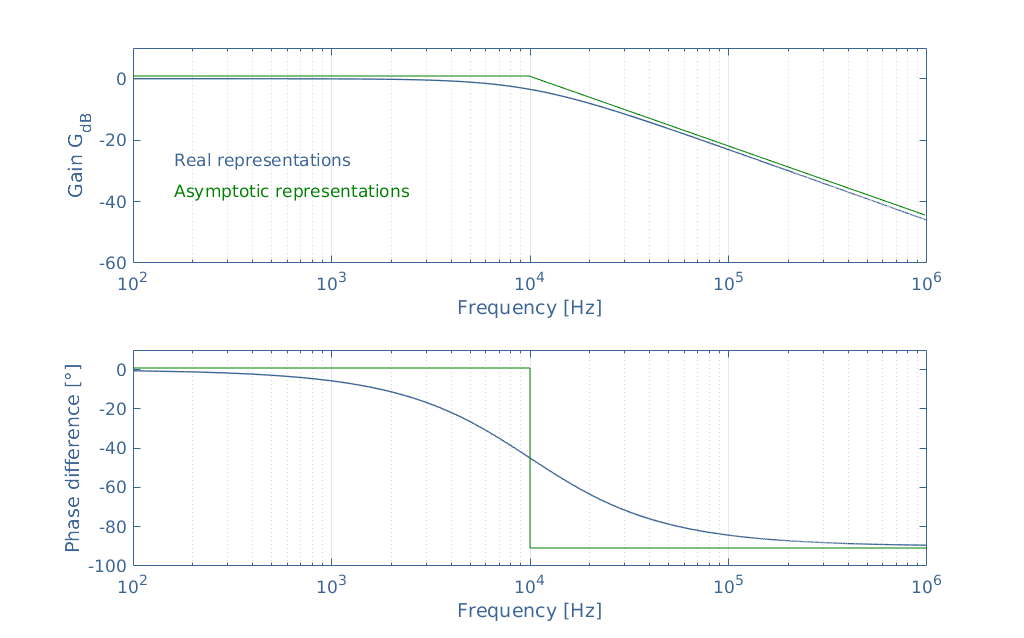
The Bode diagram of an electronic circuit consists of two graphs that plot respectively the gain GdB and the phase difference as a function of the frequency in logarithmic scale. Both of these graphs can have two representations that are shown in Figure 2: the real or asymptotic representation.
The real curve is associated with the analytical expression of the norm and the argument of the transfer function. The asymptotic representation is a straight-line approximation also known as Bode pole. In this section, we study the Bode diagrams of a simple series RC low-pass filter which circuit is represented in the third section.
fig 2: Real and asymptotic representations of a low-pass filter
Figure 2 gives a lot of information, but in order to make it more clear and easy to read, we consider the real representations of the gain and phase plots separately in Figure 3 and Figure 4 as following.
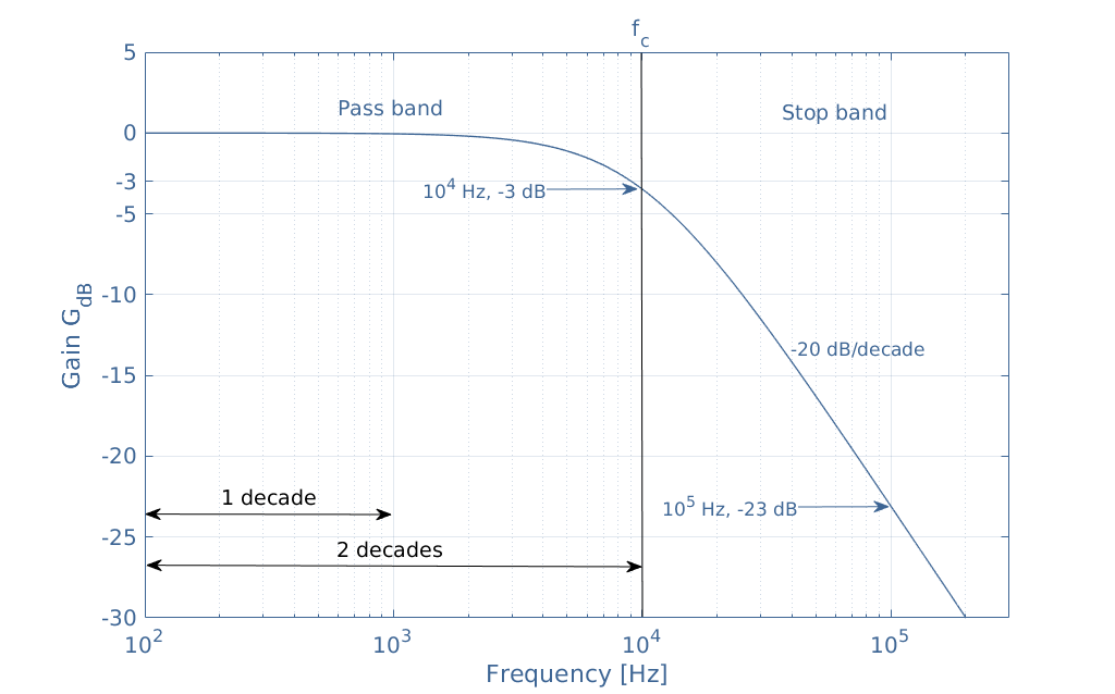
fig 3: Focus on the gain plot
The gain plot is divided into two regions labeled pass band and stop band which common border is defined by the cutoff frequency fc and in this example is equal to 10 kHz. The pass band is the region where the gain is constant and equal to 0 dB (in the Bode pole approximation), the stop band is the region where the gain is strictly smaller than -3 dB and drastically decreases, this value and rate are commented more in detail in the following.
This specific frequency is characterized by GdB(fc)=-3 dB, but why is this value so relevant? Even if each circuit has different expressions for the transfer function and the cutoff frequency, the amplitude is always divided by √2 at fc: |T(fc)|=|Tmax|/√2. When converting this ratio in dB, it comes that 20log(1/√2)=-3.
The importance of this value comes from the fact that the power is proportional to the square of the amplitude, hence when the amplitude is divided by √2, the power is divided by 2.
The cutoff frequency defines the frequency at which a loss of half of the power is observed.
One last fact can be commented in Figure 3, it is indeed highlighted that at 100 kHz the gain is -23 dB. Since at 10 kHz the gain is -3 dB, we observe a loss of -20 dB per decade, also written -20 dB/dec. We will see later in the third section that this value is typical from a first-order filter.
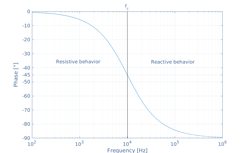
We can also extract some information from the phase plot shown in Figure 4 below:
fig 4: Focus on the phase plot
Here the same cutoff frequency marks the border between the resistive and reactive behavior. At fc, the phase-difference is indeed equal to -45°. Before fc, the circuit behaves more like a resistor, in DC and low-frequency regime, it is purely resistive. After fc, the capacitance effect increases and at high frequencies, the circuit becomes purely reactive.
Common Bode diagrams
First-order filters
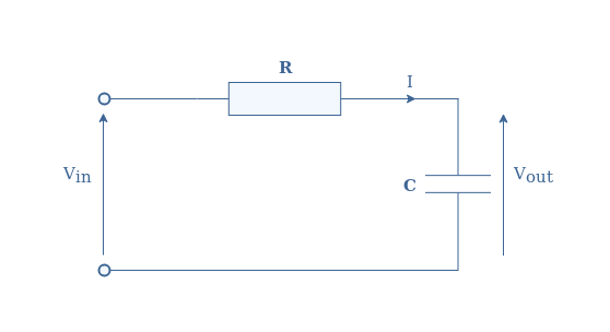
The previous section presents the Bode diagram of a series RClow-pass filter which circuit is represented in Figure 5:
fig 5: Series RC low-pass filter
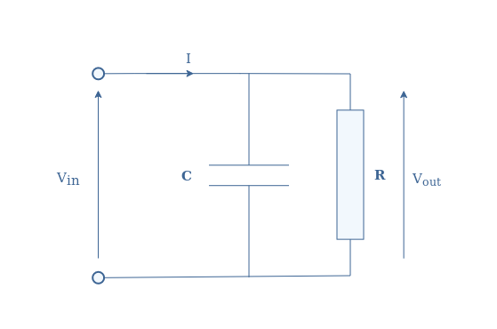
We have seen that this filter is characterized by its cutoff frequency fc=1/(2πRC), and it’s gain roll-off of -20 dB/dec. Let’s now consider another type of filter that can be realized with a parallel RC circuit shown in Figure 6:
fig 6: Parallel RC circuit
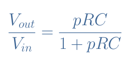
It can be shown that the transfer function of this circuit is given by Equation 1, with p=jω.
eq 1: Transfer function of the parallel RC circuit
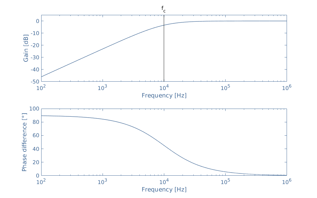
When plotting the Bode diagrams associated with this transfer function, it becomes clear that the parallel RC circuit is a high-pass filter:
fig 7: Bode diagrams of the parallel RC high-pass filter
For this example, we chose the same values of R and C than for the low-pass filter so that the cutoff frequency remains unchanged and equals 10 kHz.
Concerning the gain plot, we can say that it is the symmetrical plot of the low-pass filter with the vertical line given by the cutoff frequency value as the symmetrical axis. The pass and stop bands are inversed and a positive slope is now observed, which rate from the DC regime to the cutoff frequency is +20 dB/dec.
In fact, every first-order filter is characterized by an absolute value of 20 dB/dec for the roll-off or increase of the gain.
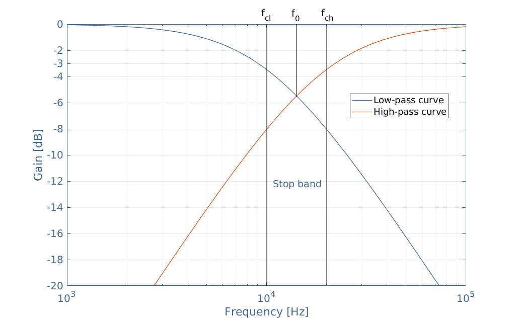
From the association of Bode diagrams, we can understand how band-pass and band-stop filters can be made. Consider indeed a low-pass and high-pass filters which cutoff frequencies are respectively fcl and fch. A band-stop filter behavior is observed if fcl<fch:
fig 8: Gain plot of the low-pass and high-pass association
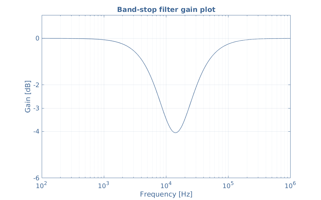
In this example, fcl=10 kHz and fch=20 kHz, the band-stop-width is therefore given by Δf=fch-fcl=10 kHz. The resonance frequency f0 is given by the geometrical mean of the cutoff frequencies: f0=√(fcl+fch)≈14 kHz. The gain plot of the band-stop filter is given by the logarithmic addition of these two curves:
A band-stop filter can be realized in practice by associating an RC high-pass filter in parallel with an RC low-pass filter and choosing appropriate values for the resistor and capacitor in order to observe the desired behavior.
The dual-circuit of the band-stop filter can be made with the series association of the same RC filters. In this case, the cutoff frequencies must respect the inequality fch<fcl:
fig 9: Band-pass filter gain plot
The formulas for the bandwidth and resonance frequency still apply for the band-pass filter.
Second-order filters
Second-order filters are characterized by the presence of at least one term p2 in the expression of their transfer function. This term comes from the fact that two reactive components are present in the circuit.
We have already presented in the Series RLC circuit and Parallel RLC circuit tutorials two circuits that respectively make second-order low-pass and high-pass filters. Their associated transfer function and Bode gain plots are also shown in these articles.
Second-order filters have the advantage of having a roll-off (for the low-pass filter) or an increase rate (for the high-pass filter) of 40 dB/dec in absolute value, therefore, rejecting faster the undesired frequencies.
Such as for first-order filters, second-order band-stop and band-pass filters can be realized with the parallel or series associations of the elementary RLC low-pass and high-pass filters.
Conclusion
Bode diagrams are a visual and efficient tool to represent the AC behavior of an electronic filter. They are associated with the transfer function of the circuit from which the gain and phase difference can be computed.
Bode diagrams can be plotted through some experimental methods in order to study and characterize an unknown circuit. The measure of the cutoff frequency, bandwidth (for band filters) and slope help us to determine the order, the components and the architecture of a circuit.
On the other hand, the knowledge of Bode diagrams of the elementary filters is essential to anticipate the behavior of a circuit and design customized filters.
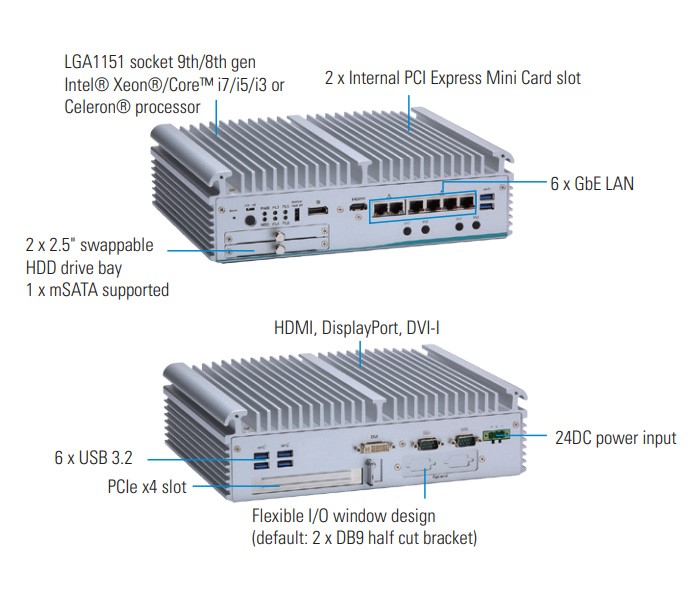
Axiomtek – a world-renowned leader relentlessly devoted in the research, development and manufacture of series of innovative and reliable industrial computer products of high efficiency – is proud to unveil its eBOX710-521-FL, a fanless embedded system powered by the workstation-grade Intel® Xeon® processor with the Intel® C246 chipset. It is also capable of offering the best quality imaging with triple independent displays. To meet different needs in automation industry, the eBOX710-521-FL has a flexible I/O window slot for ease of customization and two swappable 2.5” SATA HDD drive bays with Intel® RAID 0&1. The durable embedded system was designed to operate reliably in industrial environments with a wide operating temperature range of -40°C to 70° and vibration endurance for up to 3G. It is well-suited for machine learning, deep learning, intelligent surveillance, robotic control, edge computing, and more AIoT applications.
The eBOX710-521-FL features scalable CPU options with the Intel® Xeon® processor, 9th/8th generation Intel® Core™ or Intel® Celeron® processor to satisfy a range of performance requirements and price points. It is equipped with two 260-pin DDR4-2666 ECC/non-ECC SO-DIMM slots for up to 64GB of system memory. The workstation-grade embedded system offers complete expandability and full featured I/O, including two RS-232/422/485, one DVI-I, one HDMI, one DisplayPort, four USB 3.2 Gen2, two USB 3.2 Gen1 and six Gigabit Ethernet port. It also offers a Phoenix-type VDC power input connector, one AT/ATX quick switch, one ATX power switch, one reset switch, and one remote switch. In addition, it comes with two full-size PCI Express Mini Card slots, two SIM slots and four SMA-type antenna openings for 3G/4G, GPS, Wi-Fi, Bluetooth or other RF connections.
Advanced Features:
Intel® Xeon, 9th/8th gen Intel® Core™ i7/i5/i3 or Intel® Celeron® processor (codename: Coffee Lake Refresh)
2 DDR4 ECC/non-ECC memory supported for up to 64GB
Dual swappable 2.5″ SATA HDD drive bays with RAID 0 &1
DVI-I, HDMI, and DisplayPort with triple-view supported
6 GbE LAN, 6 USB 3.2 and 1 PCIe x4 expansion slot
Flexible I/O window supported
“Axiomtek’s eBOX710-521-FL delivers enhanced workstation performance with the latest Intel® Xeon® processor. This dependable embedded system supports ECC memory to enable automatic detection and repair of memory errors, reducing the possibility of system crashes and data corruption to ensure reliable and responsive workstation performance. To fulfill diverse requirements in automation applications, this flexible embedded system also comes with one PCIe x4 expansion slot which can support different types of I/O cards,” said Janney Lee, a product manager of Product PM Division at Axiomtek. ”Besides, the industrial-grade embedded system is compatible with Windows® 10 IoT and Linux operating systems.”
Availability
Axiomtek’s eBOX710-521-FL is now available for purchase. For more product information or customization services, please visit our global website at www.axiomtek.com or contact one of our sales representatives at info@axiomtek.com.tw.