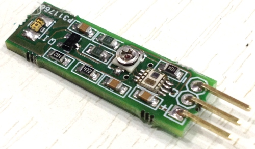
This reflective sensor module is a high-performance 0-5 cm active proximity detector. The sensor can provide a range up to 50cm with higher current infra-red LED and current limit resistor R2, R4 used across IR LED. Because the sensor operates on an absolute reflectance threshold principle, it avoids the ambiguity of motion-based proximity systems. The Si1102 consists of a patented, high-EMI immunity, differential photodiode and a signal-processing IC with LED driver and a high-gain optical receiver. Proximity detection is based on measurements of reflected light from a strobed. The sensor board is based on Si1102 from Silicon Labs. The Si1102 is an active optical reflectance proximity detector with a simple on/off digital output whose state is based upon the comparison of reflected light against a set threshold. An LED sends light pulses whose reflections reach a photodiode and are processed by the Si1102’s analog circuitry.
Reflectance based Proximity Sensor using Si1102 – [Link]
This reflective sensor module is a high-performance 0-5 cm active proximity detector. The sensor can provide a range up to 50cm with higher current infra-red LED and current limit resistor R2, R4 used across IR LED. Because the sensor operates on an absolute reflectance threshold principle, it avoids the ambiguity of motion-based proximity systems. The Si1102 consists of a patented, high-EMI immunity, differential photodiode and a signal-processing IC with LED driver and a high-gain optical receiver. Proximity detection is based on measurements of reflected light from a strobed. The sensor board is based on Si1102 from Silicon Labs. The Si1102 is an active optical reflectance proximity detector with a simple on/off digital output whose state is based upon the comparison of reflected light against a set threshold. An LED sends light pulses whose reflections reach a photodiode and are processed by the Si1102’s analog circuitry.
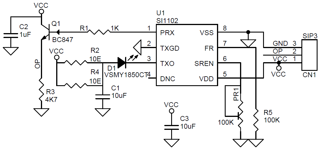
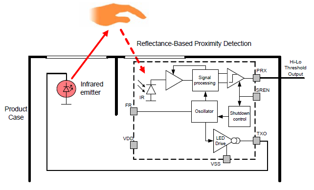
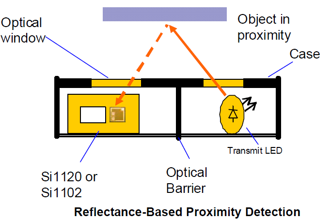
If the reflected light is above the detection threshold, the Si1102 asserts the active-low PRX output to indicate proximity. This output can be used as a control signal to activate other devices or as an interrupt signal for microcontrollers. Note that when the proximity of an object nears the pre-set threshold, it is normal for the PRX pin to alternate between the on and off states. To achieve maximum performance, high optical isolation is required between two light ports, one for the transmit LED and the other for the Si1102. The Si1102 light port should be infrared-transmissive, blocking visible light wavelengths for best performance. This dual-port active reflection proximity detector has significant advantages over single-port, motion-based infrared systems, which are good only for triggered events. Motion detection only identifies proximate moving objects and is ambiguous about stationary objects.
The Si1102 allows in- or out-of proximity detection, reliably determining if an object has left the proximity field or is still in the field even when not moving. The Si1102 proximity detector is designed to operate with a minimal number of external components. The trimmer potentiometer is used to set the proximity detection threshold. The Si1102 periodically detects proximity at a rate that set programmed by a single resistor (R5). The part is powered down between measurements. The resulting average current, including that of the LED, can be as low as a few microamperes, which is well below a typical lithium batteries self-discharge current of 10 μA, thus ensuring the battery’s typical life of 10 years. When enabled (SREN driven low by a microcontroller or PR1 pull-down potentiometer exists), the Si1102 powers up, and then pulses the output of the LED driver.
Light reflected from a proximate object is detected by the receiver, and, if it exceeds a threshold set by the potentiometer at the SREN pin, the proximity status is latched to the active low PRX output pin. The output is updated once per cycle. The cycle time is controlled through the optional R5 resistor.
Strobe Frequency Resistor (R5)
A resistor to VSS controls the proximity-detection cycle frequency. With no resistor, the sample frequency is, at most, 5.0 Hz. With FR shorted to VSS the sample frequency is typically 250 Hz. With a 100 kΩ resistor, the sample frequency is typically 7 Hz, maximum 30 Hz. The voltage on FR relative to the ground is only about 30 mV.
Note: It is important to have an optical barrier between the LED and the Si1102. The reflection from objects to be detected can be very weak since, for small objects within the LED’s emission angle, the amplitude of the reflected signal decreases in proportion with the fourth power of the distance.
Features
Supply 5V DC
Output High TTL Signal When Object Detect
Infra-Red 100mA LED 0805 Package
Output normally high; goes low when proximity is detected.
Sampling Strobe Rate 30Hz (Can be alter using R5, Refer datasheet of IC Si1102)
Detection Range 5cm (50cm Range Possible with Higher Current IR LED Proper Optics)
Flow rate and volume helps tell the amount of fluid going into, or through a particular vessel. For certain process automation applications, this simple-sounding fluid measurement task is so critical to the success of the project that, failure to get it right, could bring the entire process to its knees. This is why for today’s tutorial, I thought it will be cool to look at this nice water flow sensor; the YF-S201, and its use in an Arduino based project.
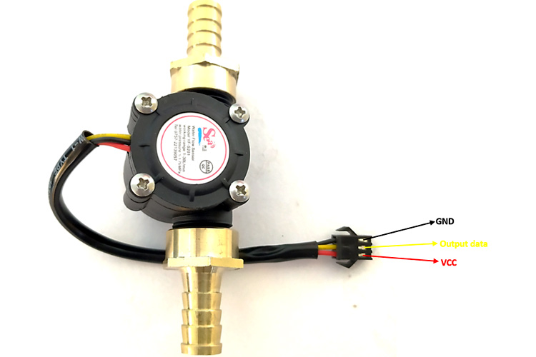
The YF-S201 water flow sensor consists of a pinwheel sensor that measures the quantity of liquid passing through it.
YFS201
The sensor uses the principles of electromagnetism, such that, when liquids flow through the sensor, the flow action impacts the fins of a turbine in the sensor, causing the wheel to spin. The shaft of the turbine wheel is connected to a hall effect sensor so that with every spin, a pulse is generated, and by monitoring that pulse with a microcontroller, the sensor can be used in determining the volume of fluid passing through it.
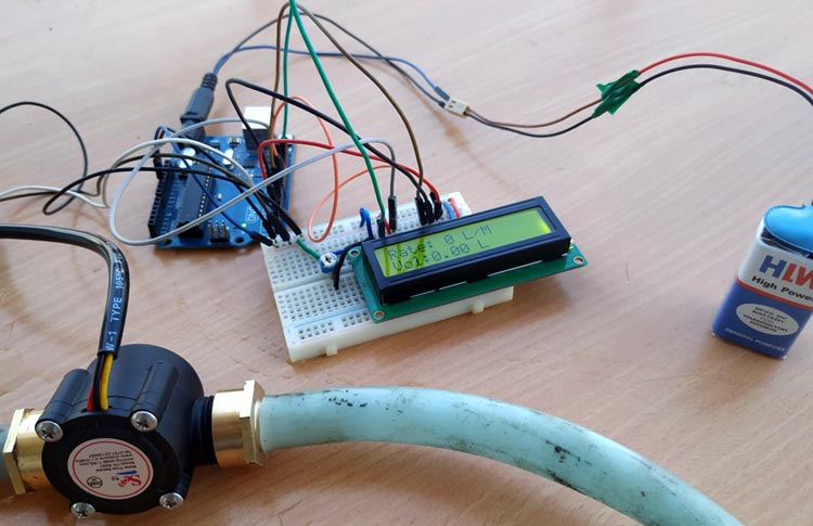
As the microcontroller for today, we will use the Arduino Uno. The Uno will be used to count the number of pulses detected over time and calculate the flow rate (in liters/hour) and total volume of fluid that has passed through it using the total number of pulses. The result, flow rate and volume, will then be displayed on a 16×2 LCD so as to provide a visual feedback to the user. If the 16×2 LCD is not available, you can view the data over the Arduino Serial Monitor.
At the end this tutorial, you would know how to use the YF-S201 flow sensor with the Arduino.
Required Components
The following components are required to build this project:
YF-S201 Water Flow Sensor
Arduino UNO (or any other compatible board)
16×2 LCD Display
Jumper Wires
Breadboard
Power Bank or Battery Pack.
Schematics
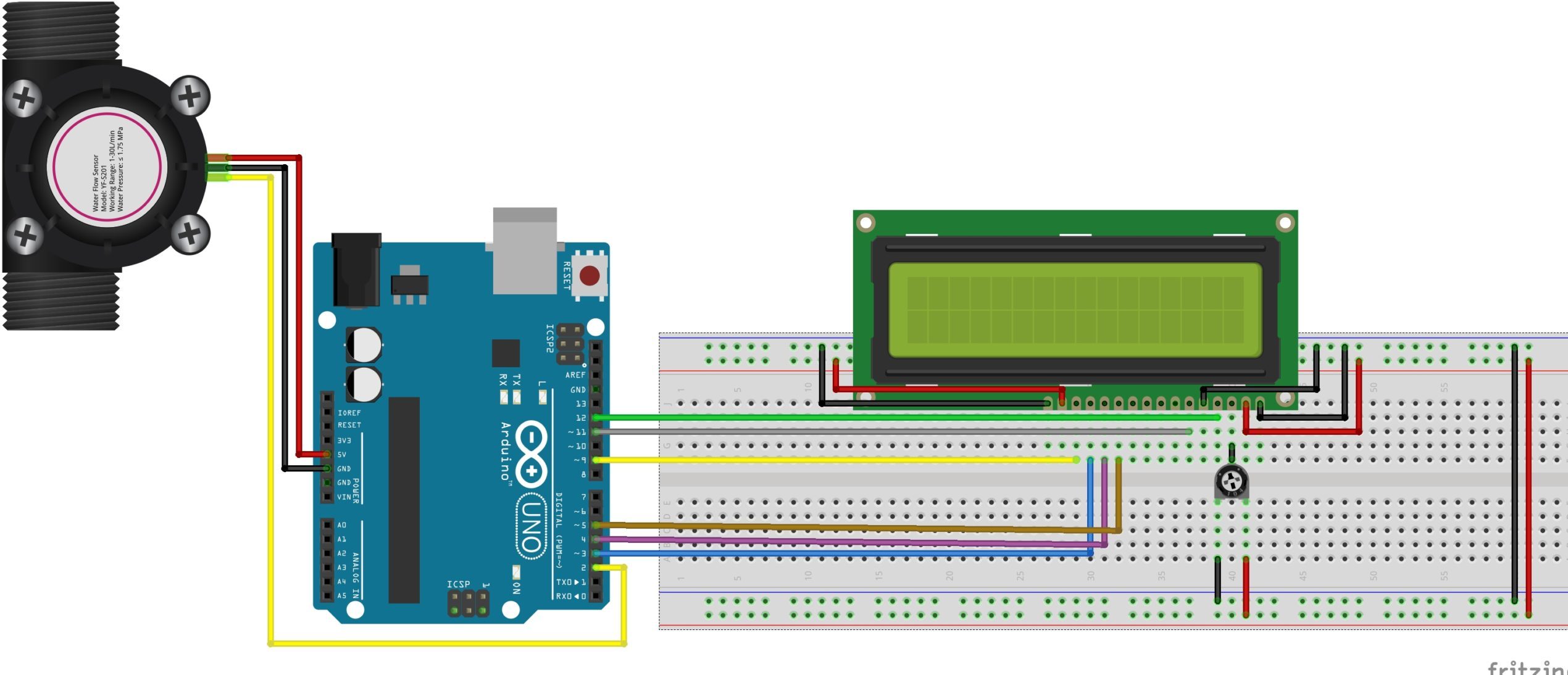
Connect the components as shown in the schematics below:
Schematics
To make reading the sensor and calculating flow easy, the interrupt feature of the Atmega328p on the Ardunio is employed, as such, the signal pin of the YF-S201 is connected to one of the interrupt-enabled IOs of the Uno (in this case, pin D2). The LCD, on the other hand, is connected in a 4-bit mode to the Arduino. To save some time on connections, you could also decide to use an I2C enabled version of the 16×2 LCD display. For this, you will only need to connect 4 wires from the display to the Arduino. It will, however, call for some modification in the code, so be sure you can handle it before making that decision.
A breakdown of the connection showing how the components are connected, pin-to-pin, is provided below;
Double-check the connections to make sure everything is as it should be before proceeding to the next section.
Code
The idea behind the sketch is simple: monitor the signal pin of the YF-S201 to detect when the hall sensor is triggered (flow is detected) and increment a variable to show the increased inflow. However, to do that efficiently and accurately, we will use the interrupt feature of the Arduino such that whenever the hall sensor detects the rotating magnet, a rising edge interrupt is fired and registered by the Arduino. The total number of interrupts fired over a particular time is then used in generating the flowrate and the total volume of liquid that has traveled through the flow meter.
Since the flow determination is pretty straight forward, the only library we will use for this tutorial is the Arduino Liquid Crystal library. The library contains functions that make it easy to interface the 16×2 LCD with an Arduino. The library is included with the Arduino IDE but in case it’s not, it can be installed via the Arduino IDE Library Manager.
With the library installed, we then move to write the Arduino Sketch for the project.
As usual, I will go over the code and explain parts of it.
The code starts with the inclusion of the Liquid crystal library:
#include <LiquidCrystal.h>
It is followed by the declaration of some variables that will be used to store data later and the creation of an instance of the liquid crystal library.
Next, we create the flow() function. This function is called whenever the interrupt is detected and it will increment the flow counter which will serve as an indication of the flow rate.
void flow () // Interrupt function
{
   flow_frequency++;
}
Next, we write the void setup() function. We start the function by including initializing serial communication so as to have access to the serial monitor for debugging purposes.
Serial.begin(9600);
Next, we declare the Arduino pin to which the signal pin of the flow sensor is connected, as an input pin. We create a pull-up on the pin by setting it “HIGH” and set up a “Rising” edge interrupt on it with the flow() function we created earlier as the callback.
We wrap up the setup function by calling the millis() function to keep track of the time since flow rate as a measure of the flow within a particular time frame.
The loop starts by comparing how much time has elapsed since the last loop. The flow frequency, obtained via the interrupt action, is then divided by time (in minutes) and the value is displayed as the flowrate. The value is also added to the existing volume(vol) and displayed as the total volume of fluid that has passed through the sensor.
Go over your connections to be sure everything is as it should be. With this done and the code complete, connect the hardware to your computer and upload the code to the Arduino board. If successful, you should see the display come up as shown in the image below.
Connect some pipes to it using whatever means is easy for you and pass some water through the flow sensor. You should see the flowrate being displayed on your screen, vary with the intensity of water flow, and you should also see the volume increase as more water flows through it.
If you don’t have the tubes/pipes for water around at that instant, you can blow some air into the sensor. You should hear the rotor in spin and the values on the LCD should increase.
Flowrate/ volume metering is a very important part of several industrial and even individual consumer processes. It provides to not only monitor consumption but also meter supply and I believe applications like smart water meters and automated fluid dispensers should give you tons of insights into how this seemingly basic project could be transformed into an amazing super useful product.
That’s it! feel free to reach me via the comments section for help with any challenge you might have replicating the project.
Texas Instruments’ eFuse can be used for hot-swap and power rail protection applications
Texas Instruments’ TPS1663 is an easy-to-use, positive 60 V, 6 A eFuse with a 31 mΩ integrated FET. Protection for the load, source, and the eFuse itself are provided along with adjustable features such as accurate overcurrent protection, fast short circuit protection, output slew rate control, overvoltage protection (OVP), and undervoltage lockout (UVLO). The device includes adjustable overcurrent functionality. PGOOD can be used for enabling and disabling control of the downstream DC/DC converters.
The shutdown pin provides external control for enabling and disabling the internal FET and placing the device in a low current shutdown mode. For system status monitoring and downstream load control, the device provides fault and precise current monitor output. The MODE-pin allows flexibility to configure the device between the two current-limiting fault responses (latch-off and auto-retry). The devices are available in a 4 mm × 4 mm 24-pin VQFN package and are specified over a -40°C to +125°C temperature range.
Features
Operating voltage: 4.5 V to 60 V (absolute max: 67 V)
Integrated 60 V, 31 mΩ RON hot-swap FET
Adjustable current limit: 0.6 A to 6 A (±7%)
Low quiescent current: 21 µ in shutdown
Adjustable UVLO and OVP cut-off with ±2% accuracy
PGOOD
Package: VQFN
Adjustable output slew rate control for inrush current limiting:
Charges large and unknown capacitive loads through thermal regulation during device power-up
Selectable OVC fault response options between auto-retry and latch-off (MODE)
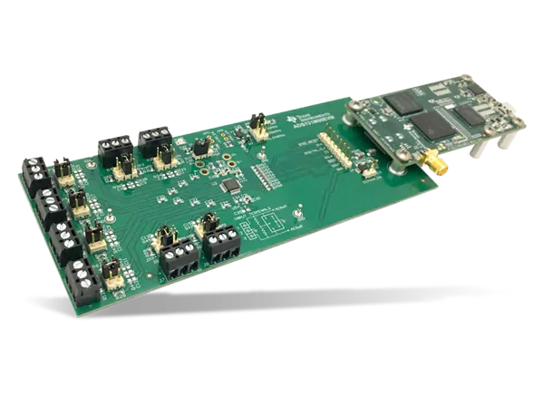
Texas Instruments’ 24-bit, 32 kSPS ADC is optimized for cost-sensitive applications that require simultaneous sampling
Texas Instruments’ ADS131M08 8-channel, simultaneously-sampling, 24-bit ΔΣ ADC offers wide dynamic range, low power, and energy-measurement-specific features. These features make the device ideal for energy metering, power metrology, and circuit breaker applications. The ADC inputs can be directly interfaced with a resistor-divider network or a power transformer to measure voltage or to a current transformer or a Rogowski coil to measure current.
The individual ADC channels can be independently configured depending on the sensor input. A low-noise programmable gain amplifier (PGA) provides gains ranging from 1 to 128 to amplify low-level signals. This device integrates channel-to-channel phase calibration and offset and gain calibration registers to help remove signal-chain errors.
Features
Eight simultaneously sampling differential inputs
Programmable data-rate up to 32 kSPS
Programmable gain up to 128
Noise performance:
Dynamic ranges: 102 dB (gain = 1, 4 kSPS), 80 dB (gain = 64, 4 kSPS)
High-impedance inputs for direct sensor connection:
Input impedance for gains of 1, 2, and 4 (330 kΩ), 8, 16, 32, and 64 (1 MΩ)
Low power consumption: 6.0 mW at 3 V AVDD and DVDD
Package: 32-pin TQFP or 32-pin WQFN
Operating temperature range: -40°C to +125°C
Applications
Electricity meters: commercial and residential
Circuit breakers
Battery test equipment
Battery management systems
A low-drift 1.2 V reference is integrated into the device reducing printed circuit board (PCB) area. Cyclic redundancy check (CRC) options can be individually enabled on the data input, data output, and register map to ensure communication integrity. The complete analog front-end (AFE) is offered in a 32-pin TQFP or leadless 32-pin WQFN package and is specified over the industrial temperature range of -40°C to +125°C.
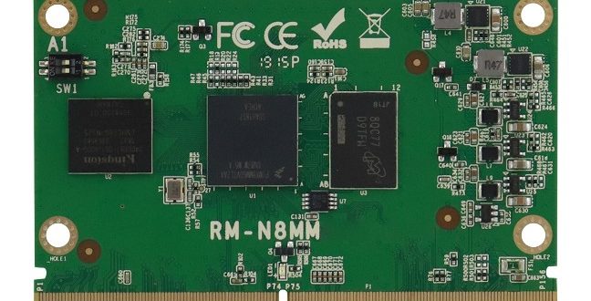
IBASE Technology, a manufacturer of application-specific embedded computer platforms, has announced the release of the RM-N8MMI SMARC 2.0 CPU Module built with NXP ARM Cortex-A53 i.MX 8M Mini Quad 1.6GHz industrial-grade processors. Together with a customised carrier board equipped with an array of serial, video and network interfaces, the RM-N8MMI solution is the perfect choice for multimedia and IoT applications that require low power and high performance in transportation passenger information and entertainment systems.
“The modular approach of the SMARC specification allows customers to take full advantage of the scalability benefit, optimized time-to-market and upgrade capability,” said Archer Chien, Director of Solution Product Planning Dept. at IBASE. “The cost-efficient RM-N8MMI offers a competitive advantage to our customers by reducing the Total Cost of Ownership (TCO) and lowering the lifecycle costs.”
The new RM-N8MMI module measures 82mm by 50mm and features Vivante’s GC 320 GPU, 2GB soldered LPDDR4 and up to 64GB eMMC flash memory. Extensive I/Os supported include 1x GbE, 2x USB 2.0 with OTG interface, 1x MIPI CSI-2 for image capture, 4x UART, 2x SPI, 2x I²S, 2x SPI and 1x PCI-E (x1) Gen2.
Shipped with extended longevity of up to 10 years, the RM-N8MMI is provided with Yocto BSP and Android 9.0 support. It is available with an industrial-grade variant that runs from -40°C to +85°C extended temperature, as well as the RP-103-SMC carrier board providing users a rich set of interfaces and 12V~24V DC input.
For more information regarding available options and configurations, please visit www.ibase-europe.com
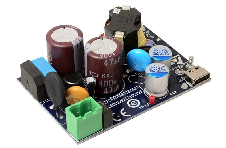
The EVLSTCH03-45WPD 45W USB Type-C® Power Delivery 3.0 adapter from STMicroelectronics is a USB-IF certified solution and reference design. The EVLSTCH03-45WPD is an isolated ac-dc power supply with a standalone USB PD controller. The board implements at the primary side a quasi-resonant flyback converter based on the STCH03 controller with optocoupler feedback for voltage regulation. This controller combines a high-performance low-voltage PWM controller chip with a 650V HV start-up cell in the same package. The STCH03 controller drives the gate of the new 650V MDmesh™ M6 technology Power MOSFET STD7N65M6.
At the secondary side, to increase the system efficiency, the rectification is based on the SRK1001 adaptive synchronous rectification controller. This controller drives the gate of the 100V STripFET™ F7 technology Power MOSFET STL110N10F7.
Always on the secondary side the CC/CV regulation loop to drive the power regulation stage and the USB Type-C® PD interface are based on the STUSB4761 controller. This controller offers the benefits of a full hardware USB PD stack allowing robust, deterministic and safe negotiation in line with USB PD standard.
The EVLSTCH03-45WPD is protected against destructive electrostatic discharge from the USB Type-C® connector using a Dual Transil array for ESD protection ESDA25L.
Key Features
USB-IF certified
USB Type-C® PD 3.0 references:
Power Brick EVLSTCH03-45WPD TID: 2071
PD Controller STUSB4761 TID: 2070
Universal ac input range VIN:
90- to 264-Vac
PD output profile:
5V – 9V – 12V – 15V @ 3A
20V @ 2.25A
Maximum efficiency at full load:
90% @ ac input range
No-load consumption (no cable plug-in):
< 30mW @ 230Vac
Energy efficiency meeting all DOE and UE CoC requirements
Isolated quasi-resonant flyback topology with adaptive synchronous rectification
Programmable output voltage and current protections
Safety according to EN60065
EMI according to EN55022 – Class B
Compact form factor: 70 x 50 X 26.8 mm
RoHS compliant
The evaluation board implements a robust adapter protected for output overvoltage, output undervoltage, output overpower and output short-circuit. This reference design, based on STMicroelectronics semiconductors, helps designers to develop adapters with a short bill of materials in order to obtain a cost-effective and fast design.
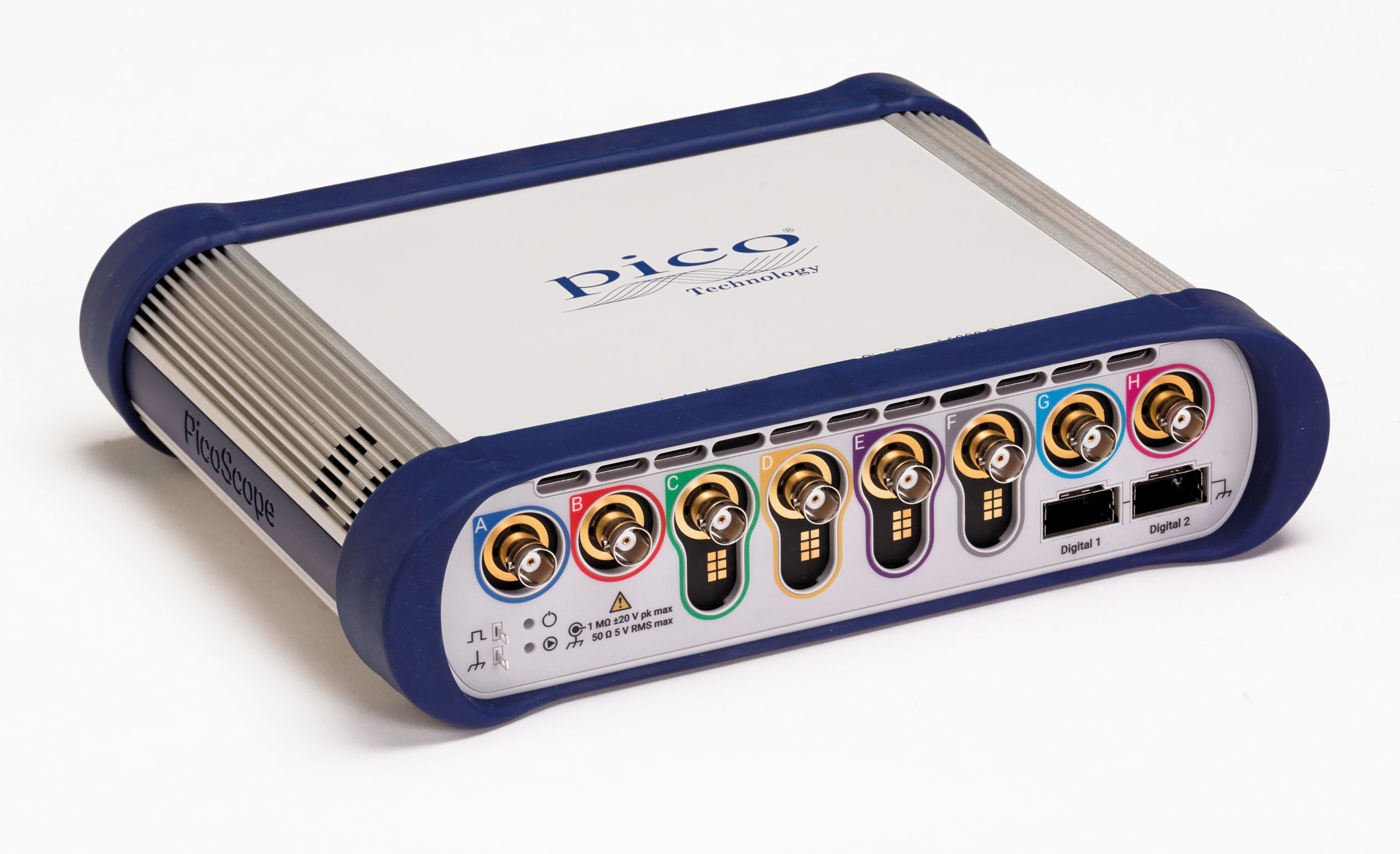
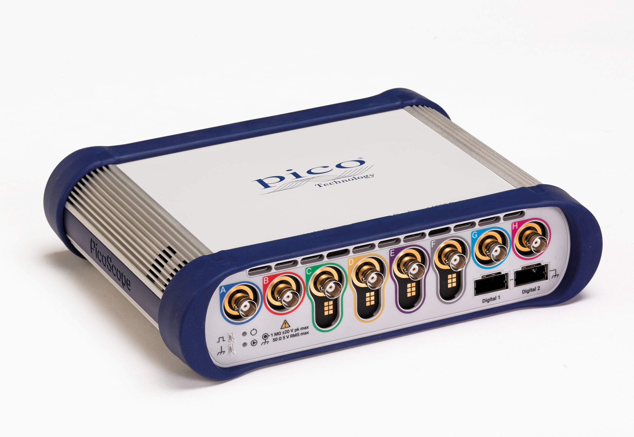
The PicoScope 6000E series brings very high speed performance to an 8 analog channel, 16 digital channel oscilloscope with 5GSa/s sampling and 4GSa deep memory.
Saelig Company, Inc. has introduced the PicoScope 6000E Series 8-channel 500MHz Oscilloscopes, which provide 8 to 12 bits of vertical resolution, 5GSa/s sampling rate, and 4GSa memory, allowing these scopes to display single-shot pulses with 200ps time resolution. The two models in the 6000 series are the PicoScope 6804E with 8-bit A/D resolution and the PicoScope 6824E with 8, 10, or 12 bits “FlexRes” resolution. Both models can operate with an extra 4 bits of resolution with the enhanced vertical resolution software feature — a digital signal processing technique built into PicoScope 6. These oscilloscopes offer 8 analog channels, plus 8 or 16 optional digital channels when using the plug-in TA369 MSO pods, enabling accurate time-correlation of analog and digital channels.
Both 6000E models include a 14-bit 200MS/s arbitrary waveform generator (AWG). Its variable sample clock avoids the jitter on waveform edges seen with fixed-clock generators and allows the generation of accurate frequencies down to 100μHz. AWG waveforms can be created or edited using the built-in editor, imported from oscilloscope traces, loaded from a spreadsheet or exported to a .csv file. The SuperSpeed USB 3.0 interface and hardware acceleration ensure that the display is smooth and responsive even with long captures. PicoScope 6 software includes decoders for many serial protocols.
With up to a million points, PicoScope’s FFT spectrum display has excellent frequency resolution and a low noise floor. A click of a button will display a spectrum plot of the active channels, with a maximum frequency of up to 500MHz. Using a 4K monitor attached to the controlling PC, PicoScope 6 software can display more than ten times the information of ordinary oscilloscopes. PicoScope software also supports dual monitors, allowing instrument control and waveforms displayed on one, and large data sets from serial protocol decoders or DeepMeasure results on the second monitor.
An optional Pico Oscilloscope Probe Positioning System holds a circuit board firmly, as well as positioning probes hands-free for up to eight probes simultaneously. Probes with compression tips make contact with points of interest on a PCB and remain in contact while measurements are taken with PicoScope software.
The 6000E’s 8 analog channels have the timing and amplitude resolution needed to reveal signal integrity challenges such as glitches, runts, dropouts, noise, distortion and ringing. This Series gives the waveform memory, resolution and analysis tools needed to test today’s high‑performance embedded computers and next-generation embedded system designs. The 6000E oscilloscopes are ideal for design engineers working with signal processing, power electronics, mechatronics, and automotive designs, and for researchers and scientists working on multi-channel high-performance experiments in physics labs, particle accelerators, and similar facilities. Supported by the PicoScope 6 software, these devices offer an ideal, cost-effective package for design, research, test, education, service, and repair.
Made by Pico Technology, Europe’s award-winning test and measurement manufacturer, the PicoScope 6000E oscilloscopes are available now from Saelig Company, Inc. their USA technical distributor.
Since the internet remains quite vulnerable to security breaches, new measures have been taken to ensure that users are able to safely interact and navigate it in no time. Earlier last year, a new security model called the FIDO2 WebAuthn (Web Authentication) that helps to eliminate all forms of password theft and replay attacks was developed by the big tech companies and accepted for recommendation by the W3C Consortium. The FIDO2 WebAuthNtechnology which has much higher security than passwords was built to help users log in to their online accounts with their mobile phone, biometrics or FIDO security keys instead of having to always remember the many passwords that they have used for different sites.
Taking it further, Electrical Engineer Andrew Ovcharov, last summer started working on developing his own FIDO2 Authenticator, the “URU Auth” derived from the abbreviation “You Are You”.
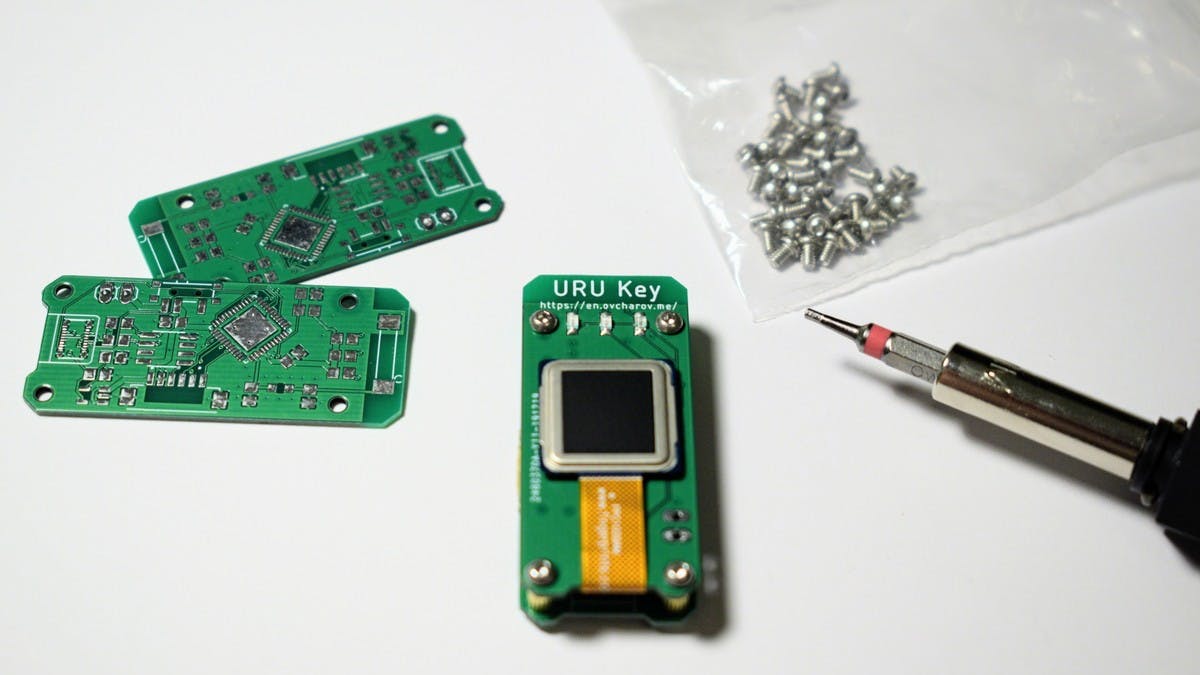
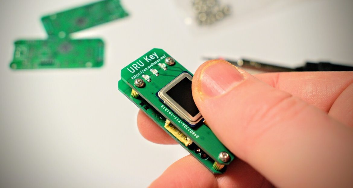
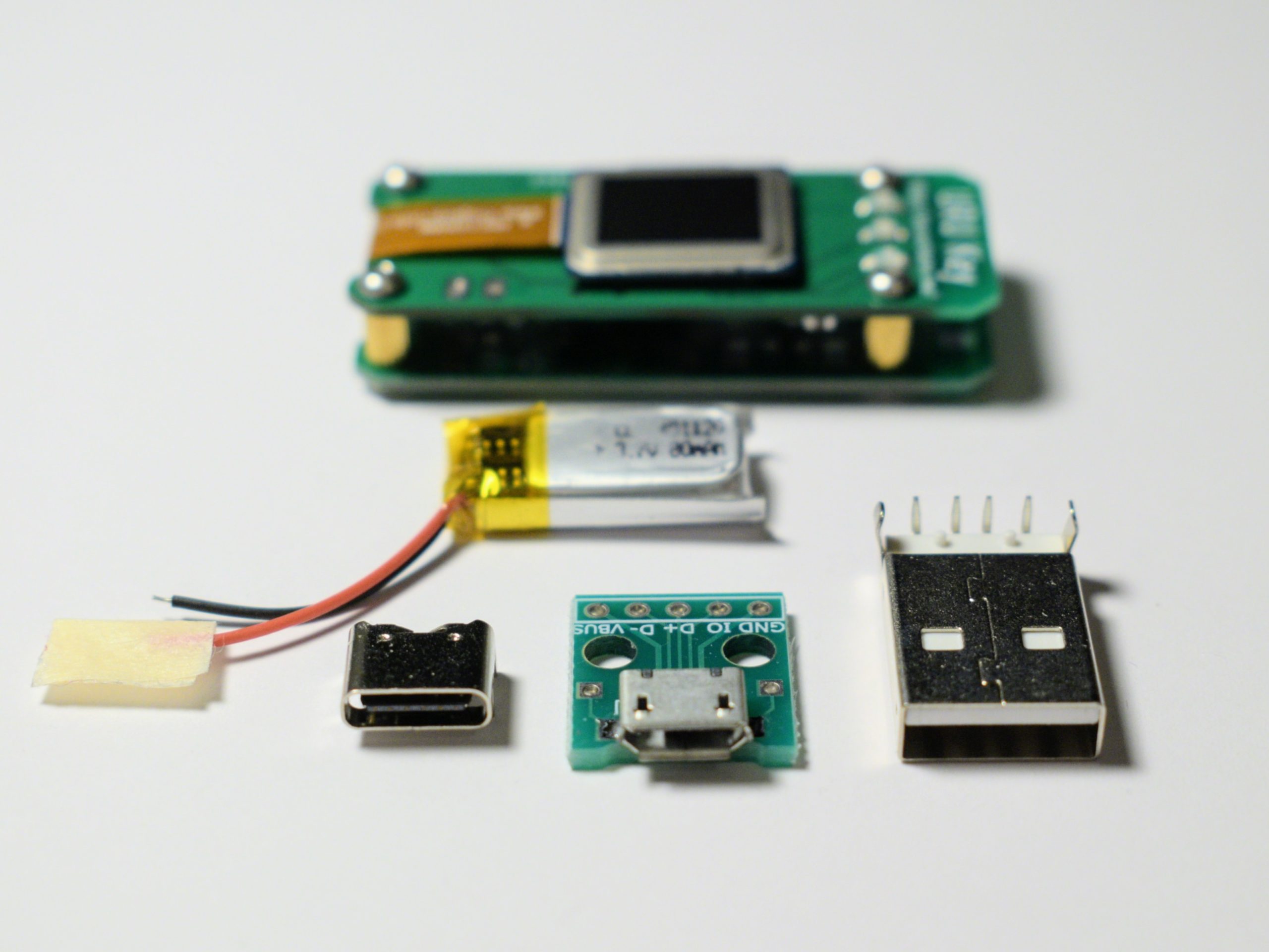
The URU key, about the size of a small flash drive, is a custom standalone wireless biometric FIDO2 WebAuthN Authenticator which uses a fingerprint scanner for authentication on WebAuthN-enabled websites. Instead of having to use mobile devices, users can power their URU key, scan a registered fingerprint and interact easily with WebAuthN web applications.
Ovcharov has been working on the URU key for about six months now and the project has successfully gone through the major developmental stages.
”…I have built a prototype board for the authenticator device, the fingerprint scanner was connected and the fingerprint image was acquired. The security chip was connected and communicated. Now all the small pieces work together as one device and the device starts to get a shape. I can hold it in my hand, I can confirm the authentication request and it makes me absolutely happy how it goes”, says the engineer.
The URU key, for now, features an ESP32 Pico D4 microcontroller for the wireless transfer of data, the GROW R300 fingerprint scanner for registering fingerprints, a few LEDs, connectors for programming and user feedback, and the ATECC508a security chip which implements the FIDO2 WebAuthN.
Ovcharov is putting more work into the project as he is currently experimenting on power options to make the device really autonomous while keeping it lightweight and pretty small.
The project’s progress is being documented beautifully on Ocharov’s website. You can follow the page to learn more about the device.
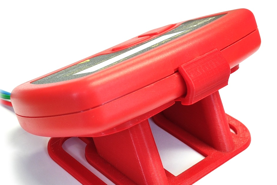
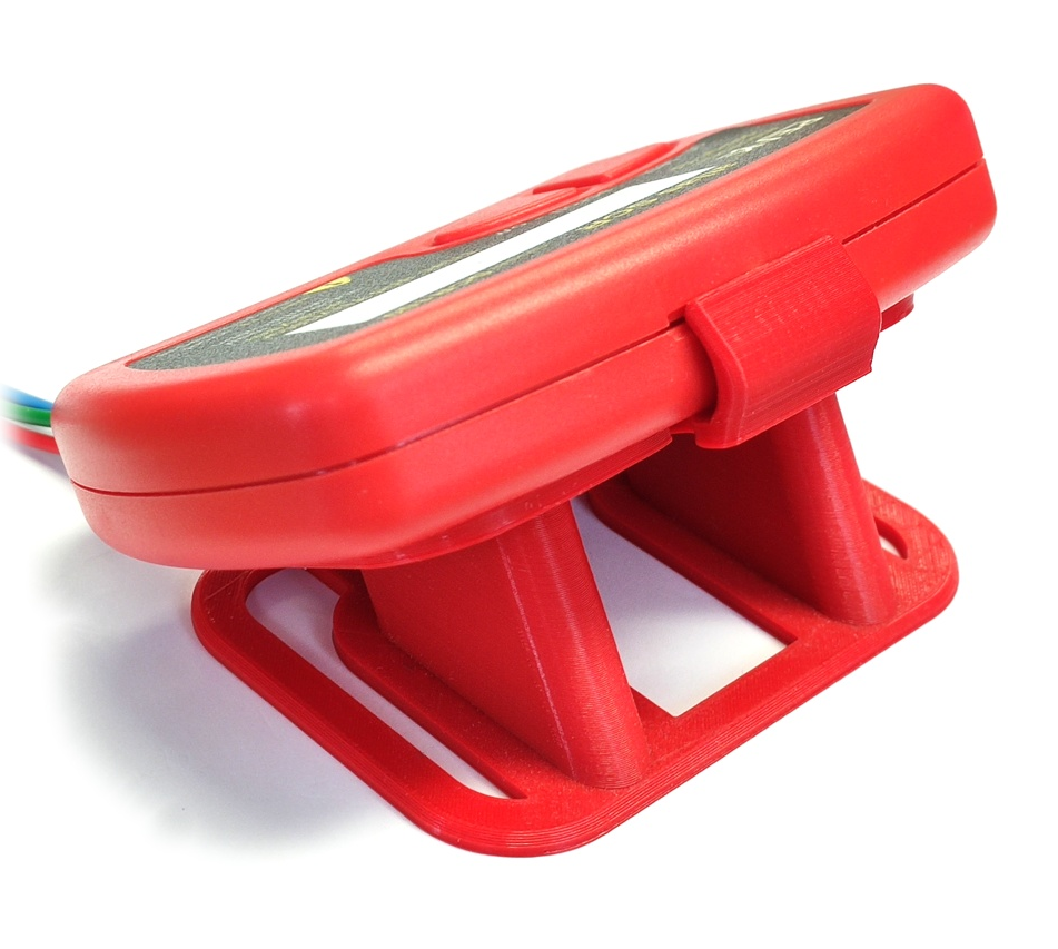
Peak Electronic Design Ltd has designed a 3D stand for their popular Peak Atlas Instruments. The stand makes the instrument sit on an angle (30°) view on top of your bench for easy reading and handing. This has been designed by Jez Siddons of Peak Electronic Design Ltd , directly using the CAD data for the Peak Atlas enclosure, so it fits like a glove and is easy to fit or remove. It also has sprung beams that allow for easy fitting. The company was kind enough to release the design so you can print your own stand. So, you can either purchase a printed stand for £9.00 or print your own by downloading the design files.
This is supplied in two parts with screws for your assembly. Price is preliminary and subject to change, as Peak says and if you purchase it, it will be printed in PLA or PETG and an unspecified color.