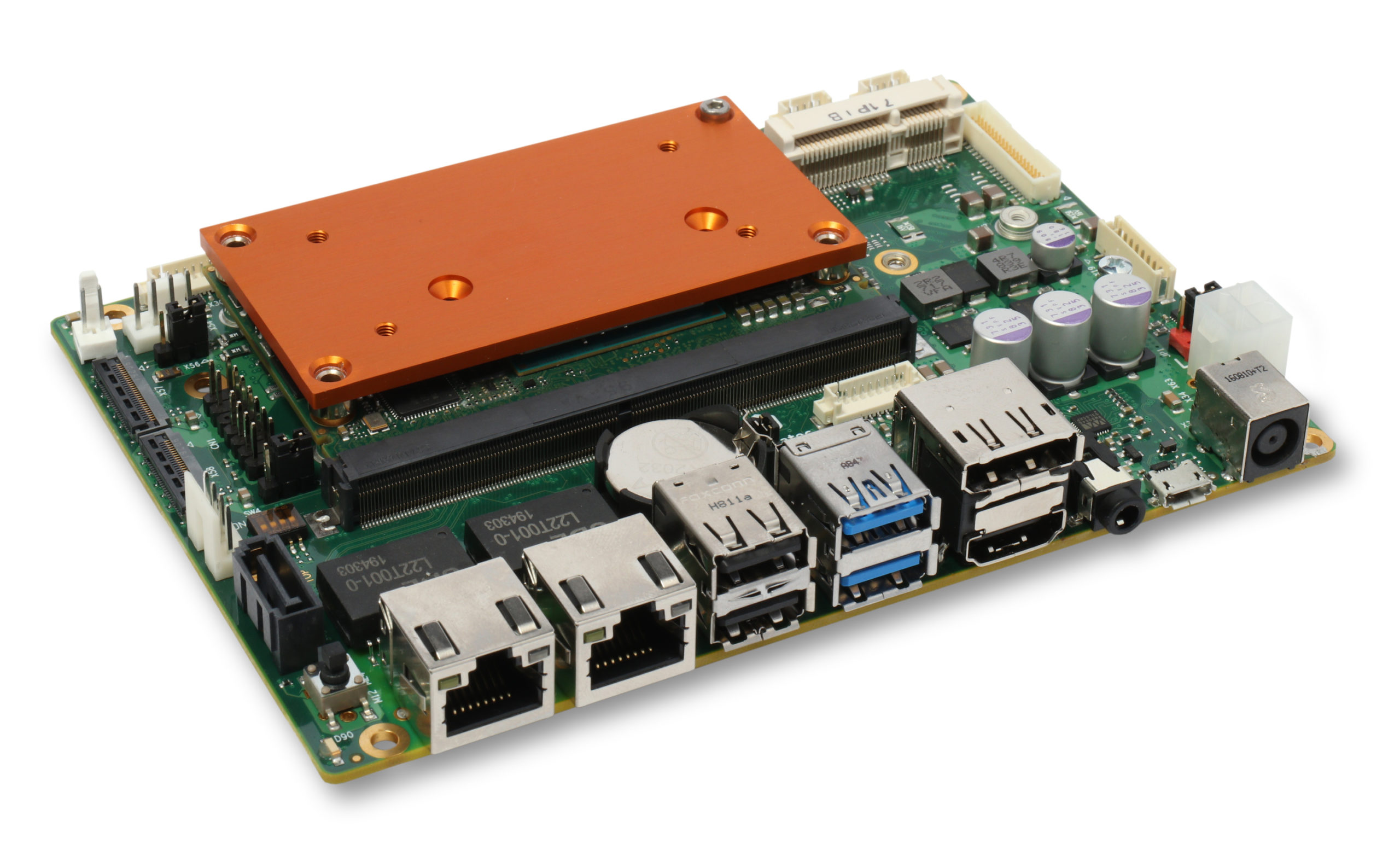
After its successful entry into the 3.5-inch SBC market in the middle of last year, congatec is now introducing a new carrier board in this standardized footprint, which impresses with a socket for Arm based SMARC modules. Its I/Os are optimized for use with congatec’s entire NXP i.MX8 module portfolio and it comes in 12 different processor configurations. Considering that the ARM processor world is traditionally characterized by proprietary designs, this 3.5-inch board design is a step further towards commercial-off-the-shelf (COTS) available standard boards and systems, offering fastest time to market. OEMs can implement them in their system solutions without any hardware development effort, using the large ecosystems of standard form factors. Rapid customization of I/Os is another benefit of such a modular design and most suitable for any small or medium sized project.
“Our new modular 3.5-inch carrier board makes Arm designs also increasingly attractive for small industrial lot sizes, which until now have been dominated by x86 technology due to a lack of suitable ARM products. And since customer-specific designs can be implemented faster and more cost-effectively with modular boards, this COTS platform is also an ideal basis for custom designs of NXP i.MX8-based systems,” said Martin Danzer, Director Product Management at congatec.
The new conga-SMC1 3.5-inch board not only features a SMARC socket for scalable processor performance, but is also optimized for MIPI cameras, which can now be connected directly and without any additional hardware. Thanks to two MIPI-CSI 2.0 connectors, it is even possible to develop systems that provide three-dimensional vision and can therefore also be used for situational awareness in autonomous vehicles. Combined with processor-integrated support for artificial intelligence and neural networks, this COTS platform offers everything developers need for smart vision systems. Comprehensive software support with precompiled binaries completes the new COTS offering.
congatec expands 3.5-inch offering to NXP i.MX8 processors
The feature set in detail
The new conga-SMC1 3.5-inch board is scalable in 12 performance steps from the most powerful i.MX 8QuadMax processors to the i.MX 8M Mini processors in 14 nm technology and the low-power i.MX 8X processors. On a footprint measuring just 146×102 mm, the conga‑SMC1 offers dual GbE, 5x USB and USB hub support as well as SATA 3 for external hard drives or SSDs. For specific expansions, the board offers a miniPCIe slot as well as an M.2 Type E E2230 slot with I2S, PCIe and USB, and an M.2 Type B B2242/2280 with 2x PCIe and 1x USB. An integrated MicroSim slot for IoT connection is also provided, next to specific embedded interfaces such as 4x UART, 2x CAN, 8x GPIO, I2C and SPI. Displays can be connected via HDMI, LVDS/eDP/DP and MIPI-DSI. The board further offers two MIPI-CSI inputs for camera connection. I2S sound can be implemented via audio jack. As they come with SMARC sockets, the new 3.5-inch conga-SMC1 can be equipped extremely flexibly with any of the 12 new NXP i.MX 8 based modules. In terms of software, congatec offers precompiled binaries with a suitably configured bootloader, appropriately compiled Linux, Yocto and Android images, as well as all required drivers that are available to congatec customers on GitHub.
The series behavior of the three elementary components of electronics has been detailed in our previous article Series RLC Circuit Analysis. In this tutorial, another association known as the parallel RLC circuit is presented.
In the first section, we present the elementary parallel RLC circuit and focus on its impedance.
The second section focuses on the AC behavior of the parallel RLC circuit. We highlight and explain the phenomenon of the resonance due to a parallel L//C configuration that explains some properties of parallel RLC circuits.
To conclude these two articles about RLC circuits, alternative configurations are presented in the last section.
Presentation
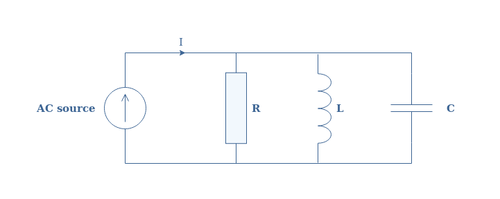
The parallel RLC circuit consists of a resistor, capacitor, and inductor which share the same voltage at their terminals:
fig 1: Illustration of the parallel RLC circuit
Since the voltage remains unchanged, the input and output for a parallel configuration are instead considered to be the current.
For a parallel configuration, the inverse of the total impedance (ZRLC) is the sum of the inverse impedances of each component: 1/ZRLC=1/ZR+1/ZL+1/ZC. In other terms, the total admittance of the circuit is the sum of the admittances of each component.
This total admittance satisfies:
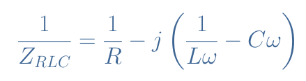
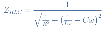
The total impedance is therefore given by Equation 1 after taking the norm of the admittance:
eq 1: Total impedance of the parallel RLC circuit
From Equation 1, it is clear that the impedance peaks for a certain value of ω when 1/Lω-Cω=0. This pulsation is called the resonance pulsation ω0 (or resonance frequency f0=ω0/2π) and is given by ω0=1/√(LC).
AC behavior
Fast analysis of the impedance can reveal the behavior of the parallel RLC circuit. Consider indeed the following values for the components of the parallel RLC circuit: R=56 kΩ, L=3 mH, and C=5 nF.
From these values, we can compute the resonance frequency of the system ω0=2.6×10⁵ rad/s. The circuit is supplied by an AC source which amplitude is 5 A and frequency varies from DC to 4×10⁵ rad/S.
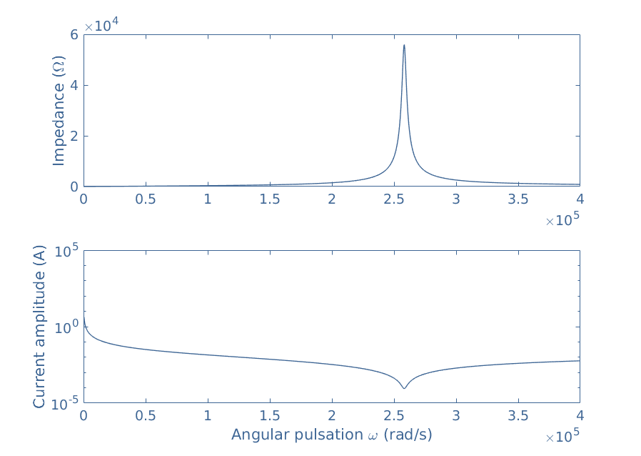
Figure 2 is a plot of the total impedance and output current as a function of the angular pulsation ω supplied to the circuit:
fig 2: Total impedance and output current of the parallel RLC circuit
It is clearly evidenced by this figure that around the resonance frequency, the impedance of the circuit peaks, which leads to a decrease of the current output around this same frequency.
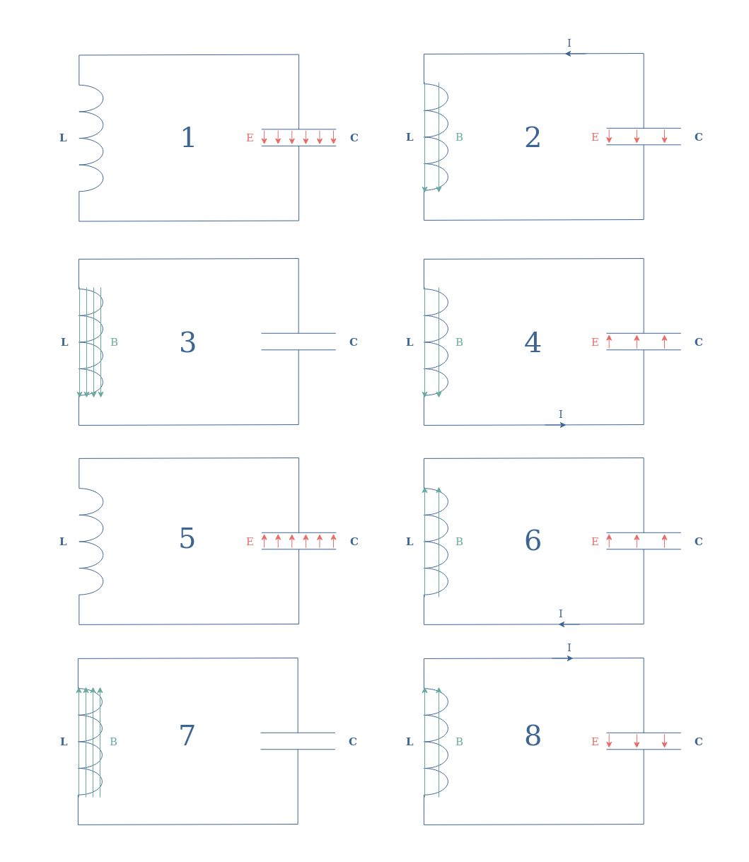
Let’s focus on what happens in the circuit and more precisely between the capacitor and inductor in order to understand this behavior. Consider, therefore, to begin with, an L//C configuration in which the capacitor is initially charged. The following Figure shows the steps involved in a cycle called resonance:
fig 3: Cycle of resonance of an L//C circuit
Many things must be commented in Figure 3. First of all, the red and green arrows represent respectively the electric field across the capacitor and the magnetic field across the inductor. The arrows indicate the direction of the fields, a fully charged component is represented with many arrows while a discharged component has none.
The numbers represent the steps of the cycle, the next step after number 8 is step number 1. As highlighted in this series of figures, the resonance phenomenon is due to mutual charges and discharges occurring between the capacitor and the inductor. The speed at which this cycle evolves is given by the resonance frequency f0=1/(2π√(LC)).
In real circuits, this cycle is of course not perpetual as internal resistors dissipate energy by Joule’s heating. However, an AC source can force the circuit to maintain this exchange of current between the inductor and capacitor.
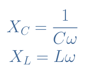
Specifically, when ωsource=ω0, the exchange of energy is maximum and all the current is flowing in between these two components and none in the mainline across a resistance (see Figure 4). Another way to understand that is through the concept of reactance. We remind that the reactances of a capacitor (XC) and an inductor (XL) are given by:
eq 2: Capacitor and inductor reactances
From the definition of ω0, it comes that XC(ω0)=XL(ω0). The currents across the components are therefore equaled but of opposite directions due to the phase-shifts of +90° in the inductor and –90° in the capacitor leading to a phase difference of 180°. This phenomenon can be seen in steps 2 and 4 or steps 6 and 8 in Figure 3.
When working around ω0, this configuration is commonly known as a rejector circuit. We detail this more in the following section where we show that an L//C circuit can be connected in series with a resistor to create a band-stop filter.
Alternative configurations
Band-stop filter
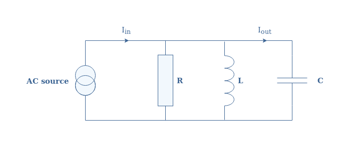
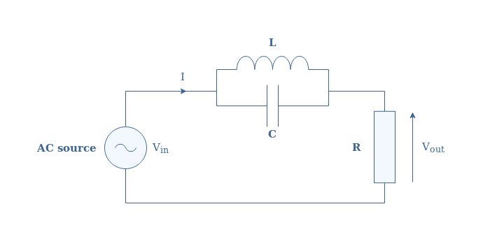
One possible interesting configuration that mixes both a parallel and series design is a parallel LC filter in series with an output load, we will call this circuit (L//C)-R in the following. A representation of this architecture is given in Figure 4 below:
fig 4: Illustration of the (L//C)-R circuit
If we call ZL//C the impedance of the parallel LC configuration, we can write that Vin=Vout+ZL//C×I. Knowing that I=Vout/R and by factorizing the expression by Vout, we can write after a few steps the transfer function of the (L//C)-R circuit:
eq 2: (L//C)-R transfer function
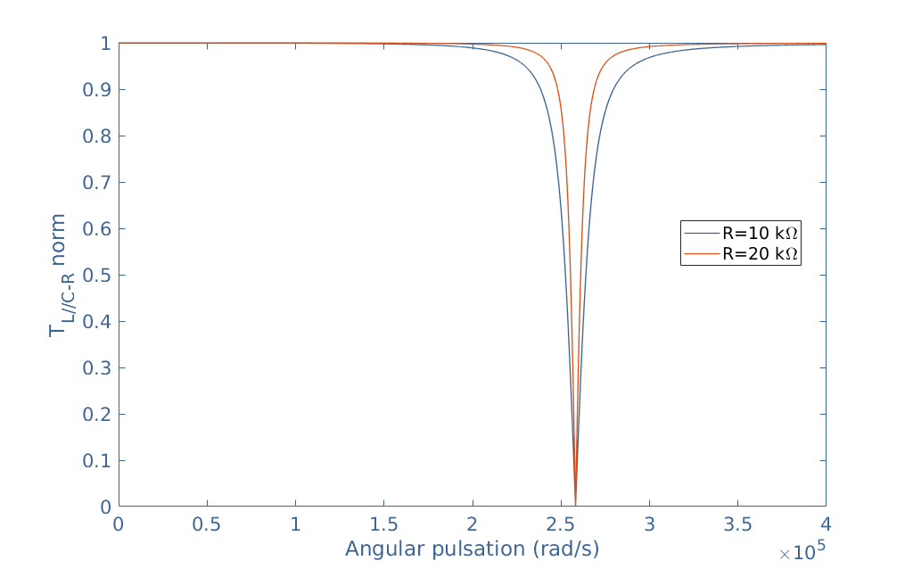
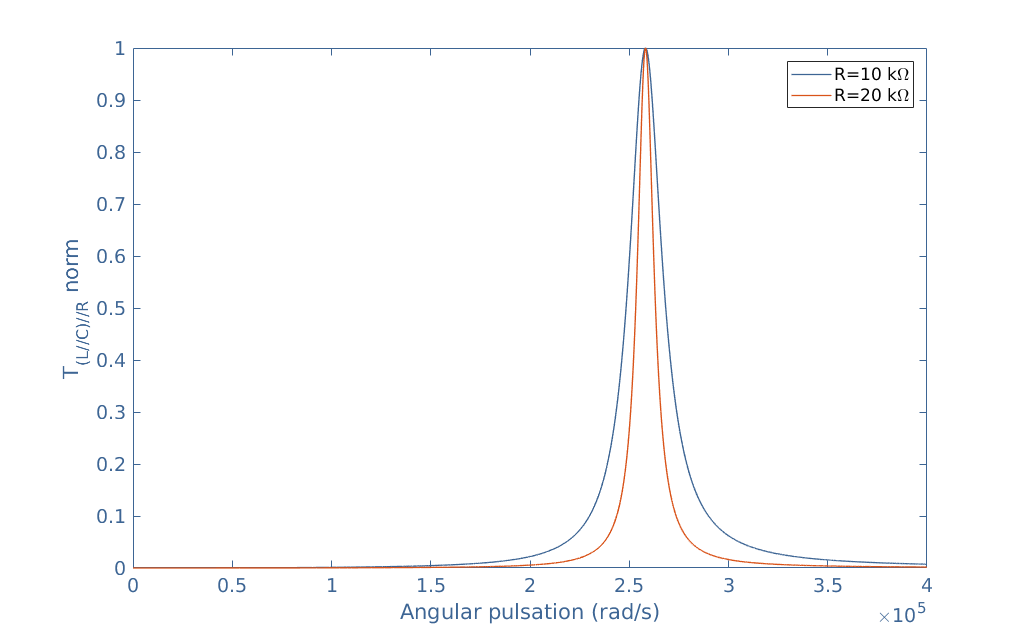
We consider L=3 mH, C=5 nF, and R=10 kΩ and 20 kΩ. It becomes clear after plotting this transfer function that the (L//C)-R circuit act as a band-stop filter around the same frequency ω0 as for the elementary parallel RLC circuit:
fig 5: Plot of the (L//C)-R transfer function
Figure 5 also highlights the fact that the bandwidth Δω of this band-stop filter becomes narrower when the resistance increases, which is in contradiction with the definition of the quality factor given in the series RLC article Qseries=(1/R)√(L/C)=ω0/Δω.
In fact, this definition is not valid for parallel circuits, the formula for a parallel configuration becomes Qparallel=1/Qseries=R√(C/L), which explains the behavior in Figure 4 previously pinpointed.
The characteristic parameters of the parallel RLC circuit are, as a matter of fact, the reciprocals to the series RLC circuit.
Band-pass filter
An interesting concept called duality enables us to directly find the behavior of a new circuit from the knowledge of another. It is deduced from the fact that the equations applying to the current or voltage to a certain configuration can be applied to the dual quantity of the dual configuration.
Let’s be a little clearer and consider again the band-stop filter example detailed above. We call this configuration (L//C)-R since a parallel (//) LC circuit is in series (-) with a resistance R. We have seen that this circuit act as a band-stop filter for the voltage.
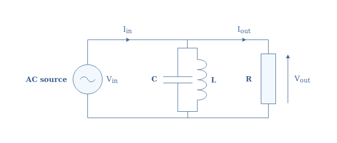
The dual of this circuit is a (L//R)//R circuit illustrated in Figure 6:
fig 6: Dual circuit of Figure 5
The duality concept tells us that this dual circuit acts as the dual of a band-stop filter, which is a band-pass filter. To verify this affirmation, we can start by writing that Iin=Iout+YL//C×Vout which is the same equation shown in the previous section but applied for the current, as stated by the duality concept. YL//C is the admittance of the configuration L//C and equals 1/ZL//C.
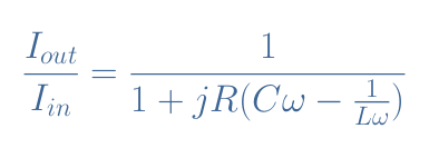
Knowing that Vout=R×Iout and by factorizing the expression with Iout, it comes:
eq 3: (L//C)//R transfer function
We can see that Equation 3 is very similar to Equation 2 but the imaginary term is inversed which leads to the band-pass filter behavior. We can consider again the same values L=3 mH, C=5 nF, and R=10 kΩ and 20 kΩ and plot this transfer function in order to conclude this section and confirm about the band-pass filter:
fig 7: Plot of the (L//C)//R transfer function
Conclusion
The behavior of a parallel RLC circuit is quite different than the series configuration. This is due to the phenomenon of reciprocal exchange of energy of the L//C circuit called resonance.
This phenomenon is due to the mutual discharges/charges occurring between an interconnected inductor and capacitor. The impedance of such a circuit theoretically tends to an infinite value at a particular pulsation ω0 called the resonance pulsation (or resonance frequency for f0). In real circuits, this impedance peaks due to internal resistive behaviors.
We have seen in the last section, that integrated in series with an output load, a band-stop filter can be made. Connected in parallel, however, leads to the opposite filter: a band-pass filter.
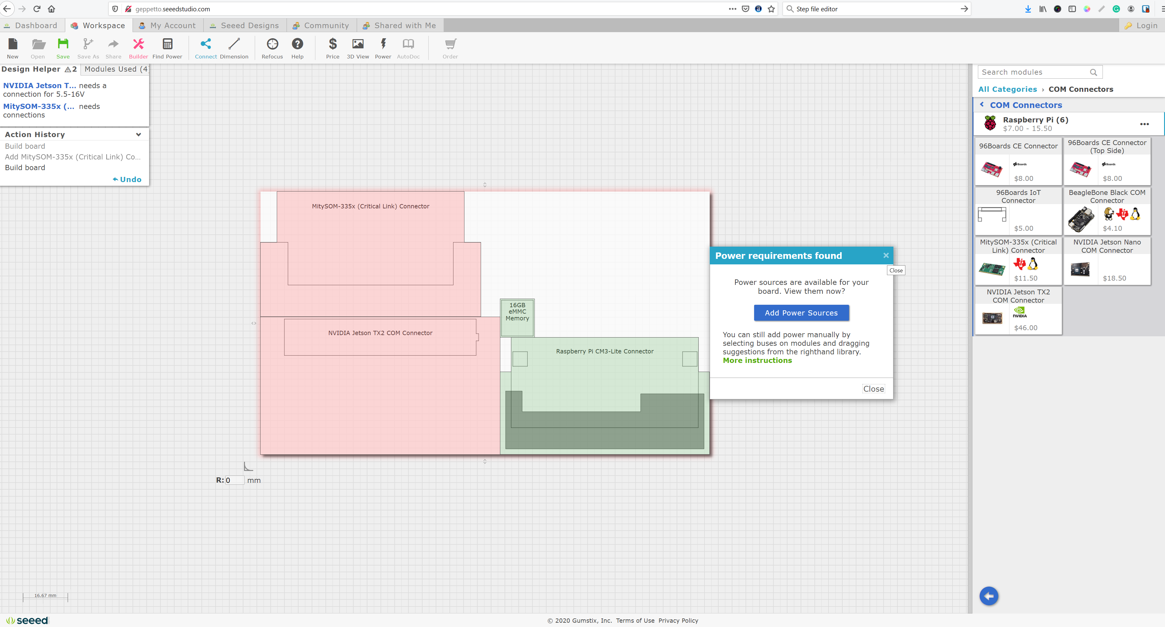
All the prototyping tools you need in Geppetto workspace on SEEED platform
Altium, announces that Seeed, the IoT hardware enabler, has embedded the Geppetto electronic design application into its Seeed platform. Seeed users can now go straight from creating a design, to manufacturing a working printed circuit board in just one session.
Geppetto is a ground-breaking cloud-based design tool that allows anyone to design electronics. Until now, Gumstix was the only company using Geppetto to create and manufacture custom electronics. Now users can create Geppetto-based designs and have them manufactured by Seeed. A hardware design can be completed in minutes, and ready to ship from 7 – 20 working days.
“Exciting new electronics are being conceived by programmers who are putting their innovative software in specialized devices,” said W. Gordon Kruberg, M.D., head of Modular Hardware, Altium, LLC.” We are thrilled to be working with Seeed to put Geppetto’s power of authorship and design in the hands and minds of this new generation of makers.”
Geppetto Key Capabilities:
Custom Web-design tool – embedded directly into the Seeed ecosystem, Geppetto provides a simple drag and drop design platform for all levels of designers enabling them to quickly build production-ready prototypes for IoT and AI applications.
Design to Build – Geppetto allows Seeed users, makers or professional engineers, to design custom hardware from the Seeed component library. The Board Builder is a menu driven application that allows users to rapidly populate a Geppetto board, making the design/prototype process trivially easy.
Rapid Manufacturing – Seeed can manufacture and deliver custom hardware directly, or with partners.
About Geppetto
Geppetto® is a free online design tool that lets almost anyone create electronic device designs. Hardware design can be created in minutes, complete with BOM documentation and pricing. Users can create multiple projects and go straight from a design to a production ready order in one session. To learn more about Geppetto’s web design tool integration into Seeed visit http://geppetto.seeedstudio.com/
About Altium
Altium LLC (ASX:ALU), a global software company headquartered in San Diego, Calif., is accelerating the pace of innovation through electronics. From individual inventors to multinational corporations, more PCB designers and engineers choose Altium software to design and realize electronics-based products. Products include Altium Designer®, Altium Concord Pro™, Altium 365®, Altium NEXUS®, CircuitMaker®, CircuitStudio®, Octopart®, and TASKING®. To learn more about Altium, visit www.altium.com.
About Seeed
Seeed provides the latest open hardware for IoT, AI and Robotic systems, and help developers scale new applications. Founded in 2008, Seeed is based in Shenzhen with branch offices in the EU, US and Japan. By partnering with top tech providers, we speed up the application of new technologies across industries. By enabling global developers to solve real-world problems, we encourage collaboration for a sustainable future. Visit www.seeed.cc for more information
Octavo Systems OSD32MP15x System In Package Releases into Production with Higher Performance and Two New Development Platforms
Octavo Systems, an ST Authorized Partner, has expanded its support of the OSD32MP15x System in Package, the smallest available STMicroelectronics STM32MP1 module, with a production release at speeds up to 800MHz, and two new development boards.
OSD32MP15x System in Package In Production at Speeds Up to 800MHz
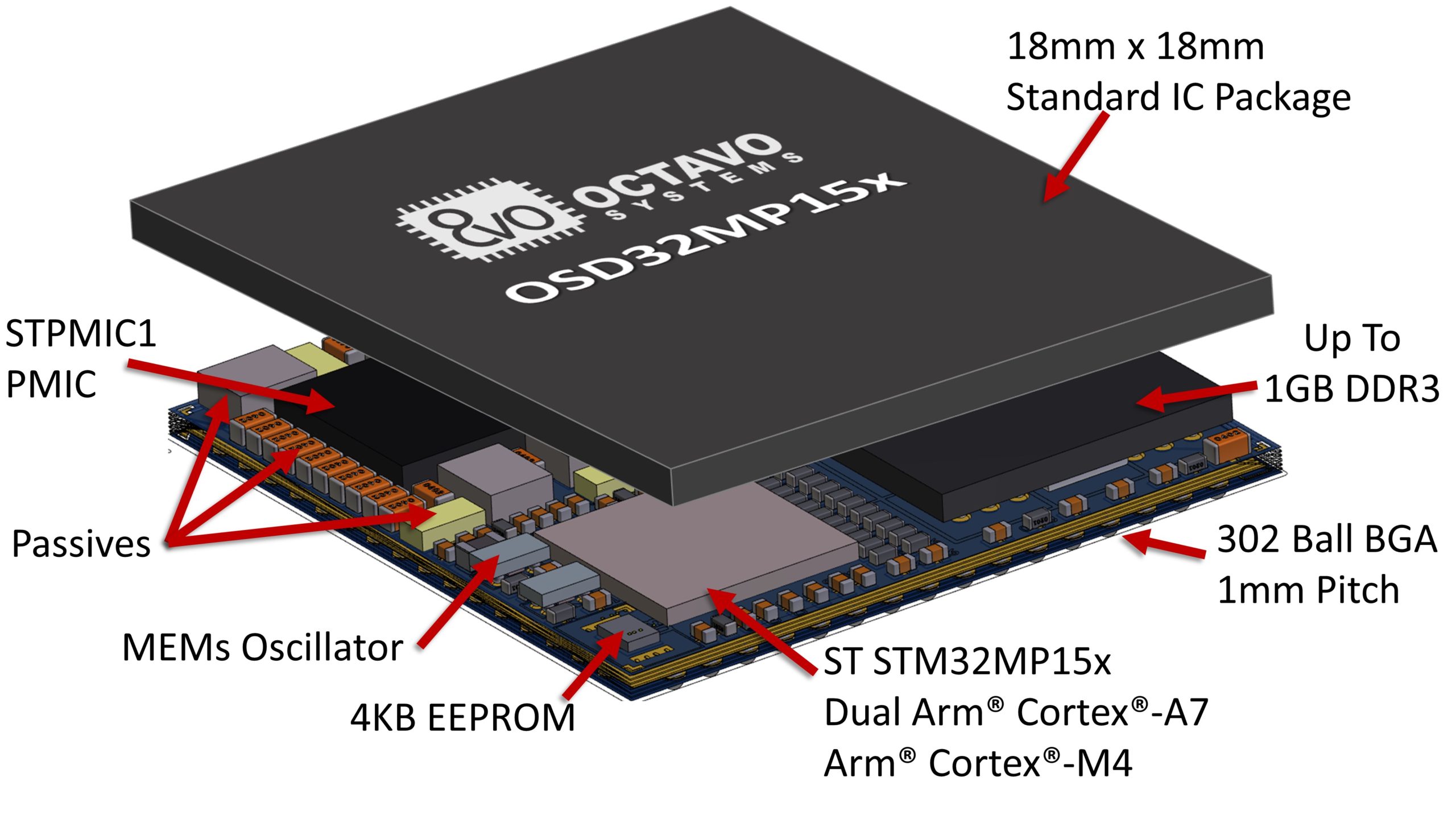
The OSD32MP15x System in Package has entered full production and can be ordered through Octavo Systems distribution partners now for delivery by the end of March. The OSD32MP15x, already shipping to customers for engineering development, integrates the STM32MP1 Dual Core Arm® Cortex® A7 + M4 microprocessor, up to 1GB of DDR3L RAM, STPMIC1A Power Management IC, EEPROM, MEMs Oscillator, and over 100 passives into a production cost saving, BGA Package. The OSD32MP15x provides complete access to all the features and performance of the STM32MP1, including the recently announced 800MHz clock speed, while removing tedious tasks like DDR routing and power sequencing. At 18mm x 18mm, the OSD32MP15x is up to 64% smaller than an equivalent system made from discrete components.
“The Octavo Systems OSD32MP15x SiP solution delivers MPU performance while allowing customers to remove complexity from their designs thanks to the MCU-like implementation, so they can focus on the value-added features of their applications,” said Ricardo De Sa Earp, General Manager of the Microcontroller Division, STMicroelectronics. “The OSD32MP15x SiP’s small size makes it ideal for space-constrained environments, while also optimizing system cost thanks to the ability to use 4 layer PCBs.”
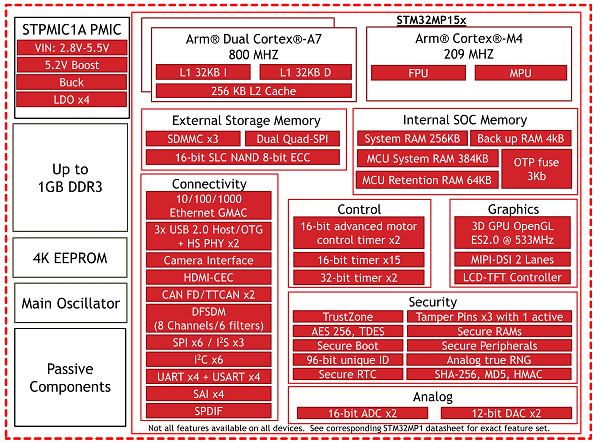
CAN FD/TTCAN x2, UART x4, USART x4,SPI x6, I2C x6, SAI x4, QSPI, SPDIF, I2S x3
eMMC/SD/SDIO Ports x3
GPIO x148
24-bit RGB Display, MIPI DSI
Camera Interface
22 Channel 16-bit ADC x2, 12-bit DAC x2
Access to all signals of the STM32MP1 TFBGA 361 package
STPMIC1 Power Management IC Features:
Single Voltage Input: 2.8V-5.5V
Integrated Boost: 5.2V
System Power: Buck LDOx4, Power Switch x2
302 Ball BGA (18mm x 18mm)
16 x 16 grid, 1mm Pitch
Case Temp Range: 0° to 85°C, -40° to 85°C
OSD32MP1-BRK Flexible Prototyping Platform
Octavo Systems also announced two hardware platforms to speed customers’ development with the OSD32MP15x. The OSD32MP1-BRK, a breakout platform, provides easy access to the I/O on the STM32MP1. The OSD32MP1-BRK features the OSD32MP157C-512M-BAA System in Package, a microSD card, 32KHz crystal, a USB port, and 2 2×30 100 mil (2.54mm) spaced headers. “The OSD32MP1-BRK provides designers a completely flexible prototyping platform. By maximizing the number of I/O that are brought out, designers can quickly build a proof of concept that more closely matches their actual system without creating their own board”, said Erik Welsh, CTO of Octavo Systems. “And since the board uses standard 100 mil headers, designers can prototype everything on a breadboard!” The OSD32MP1-BRK is designed and manufactured by Allied Component Works, LLC, a member of the Octavo Systems partner network. The product ships in April with all design files freely available on the Octavo Systems web site.
OSD32MP15x Detailed Block Diagram
OSD32MP1-RED Complete Development Platform
The second development platform is the OSD32MP1-RED Reference, Evaluation and Development board. Developed by Octavo Systems, and shipping in May, it features the OSD32MP157C-512M-BAA SiP, a WiFi and Bluetooth Module, 1GB Ethernet, 8GB eMMC, and HDMI. The OSD32MP1-RED expands easily by providing connectors that are compatible with Raspberry Pi, MikroElektronika mikroBUS™ Click, and STMicroelectronics Motor Control Header. The OSD32MP1-RED also provides connectors for a DSI display and a camera.
“The OSD32MP1-RED is a great platform for anyone developing IoT applications or applications needing a high-end HMI,” adds Greg Sheridan, VP of Strategy for Octavo Systems. “With the connectors and peripherals provided the OSD32MP1-RED makes it easy to quickly begin prototyping your system.”
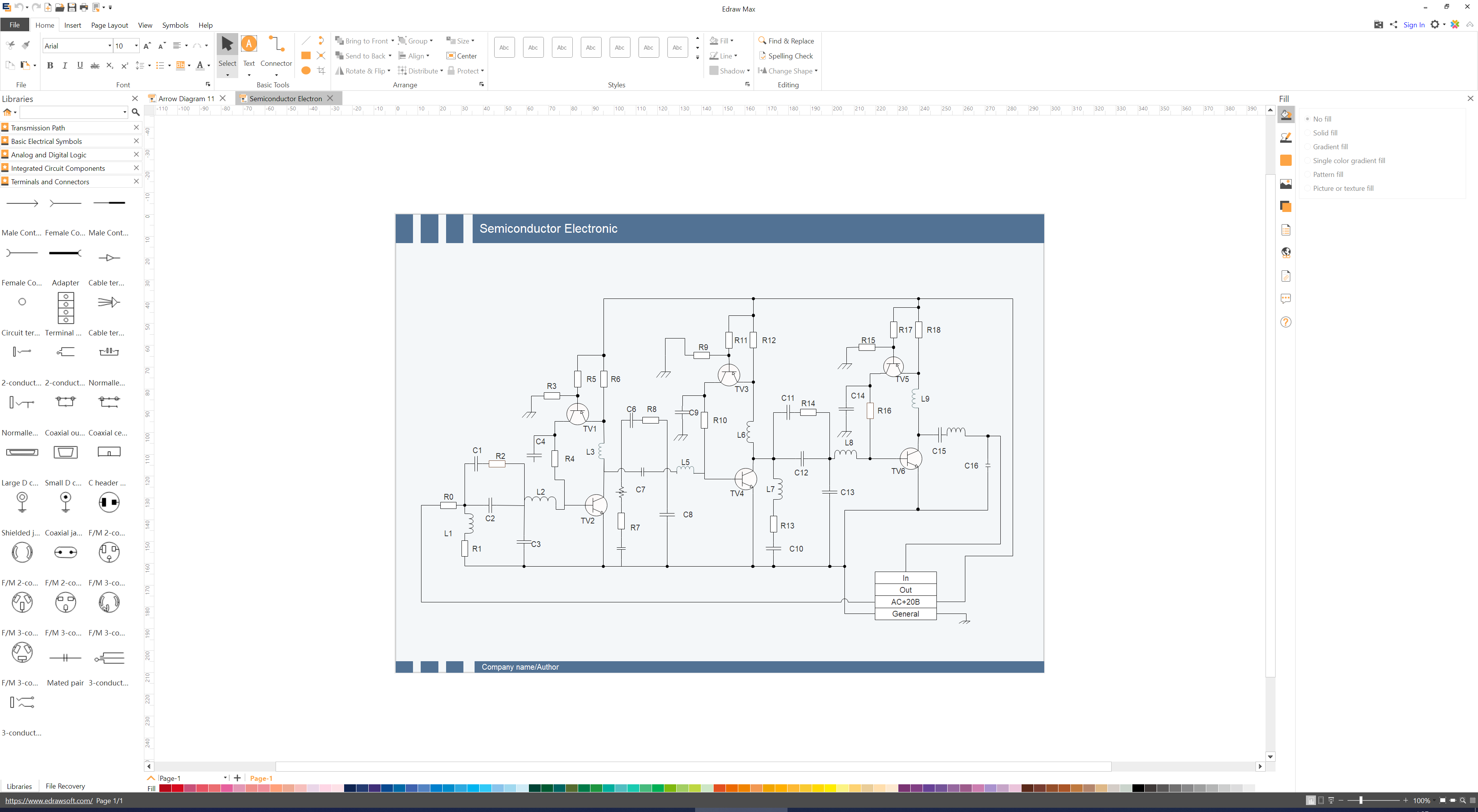
From Flowcharts to Mind Maps, diagramming is one of the easiest ways to map out thoughts, develop algorithms, and illustrate processes in a way that is easy for others to understand. For engineers and developers, diagramming provides an easy way of expressing, developing, exchanging, and documenting technical ideas, in a way that is easy for other engineers and non-technical third parties to follow. Several software tools exist for different kinds of diagrams, and with each one offering a “unique” advantage over the other, selecting the right one to use could be quite the challenge for non-populist users. This is why for today’s review, I will show two diagramming tools that I recently had the opportunity of using; the Edraw Max and Edraw MindMaster
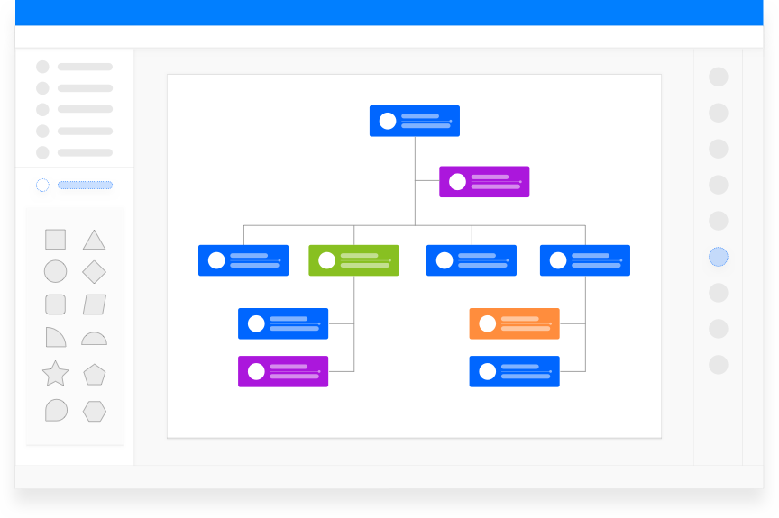
Edraw Max
Edraw Max
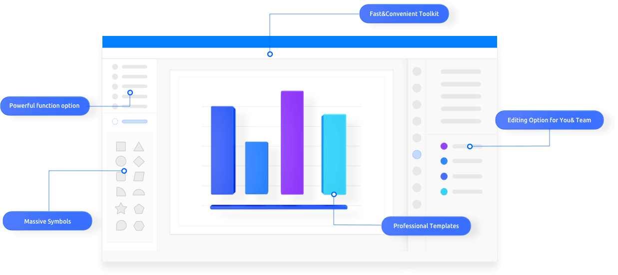
Developed by Edrawsoft, Edraw Max is an all-in-one diagramming tool with several features and massive amount of professionally designed templates and symbols that allow users create more than 280 different types of diagram and illustrations like; infographics, flowcharts, fishbone diagrams, UML diagrams, design floor plans, and office layouts to mention a few, in a fast, reliable, and easy-to-share manner.
Some of the diagrams and visualization types that can be created with Edraw Max are listed below.
Unlike most other diagramming software, Edraw Max has robust file compatibility features that allow users to import and export your drawings in a variety of familiar file formats like PDF, Word, Visio, PPT, JPEG, and HTML to mention a few, ensuring you can share your work in a manner that is easy for others to view, even if they don’t have the software.
As the nature of creative jobs becomes more remote in nature, Collaboration and OS-independence are some of the most important features of any software, and the guys at Edrawsoft understand this, as software comes with cloud storage which ensures you and your team members can work on the same project, remotely, without the need to share files around. Also, EdrawSoft recently released the Edraw Max online of the Edraw Max which possesses the same powerful features available to the software version, but with the ubiquity of the internet which allows it to be used anywhere, and on any device without OS restrictions, or the need to install the software. So you can start creating the project on your home computer, and finish it on your office computer without installing any additional software.
Edraw Max used to design a circuit schematic
The user reviews for Edraw Max are absolutely stunning as it has found its way into the hand’s different categories of professionals, from business analyst using flow diagrams for mapping out business processes to developers creating UML diagrams.
Edraw MindMaster
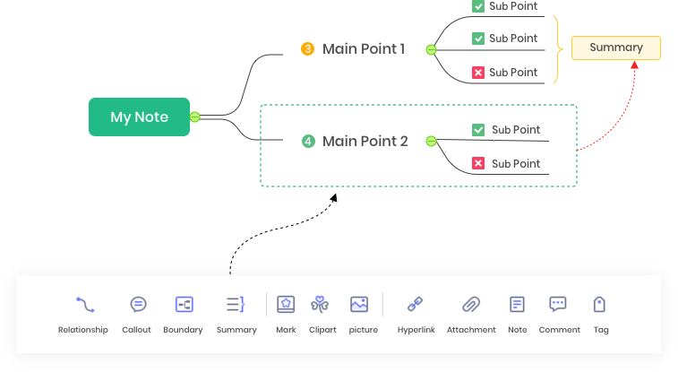
While a mind map is one of the drawing types that can be created using the EdrawMax, EdrawSoft has another software called; MindMaster, which was specifically developed for the creation of mind maps.
MindMaster is a versatile, user-friendly, collaborative, and professional mind mapping tool for Structuring Knowledge, Ideas, and plans.
To provide versatility and stimulate creativity, MindMaster comes with seemingly endless customization and personalization features that allow you to tailor your mind maps to your specific needs. For instance, In addition to a traditional radial map structure, MindMaster comes with 12 different additional structures including; bubble maps, timeline maps, and circle maps, to mention a few, all just to provide you with the right kind of structure you need to document your thoughts. Asides the structures, MindMaster also comes with as much as 33 themes, to make your maps unique, and 700+ readymade stylish clipart’s to decorate your maps and make your creative ideas easy to follow/visualize.
For each node on the mind map, MindMaster allows creators to add several descriptive information like callouts, relationships, summaries, marks, notes, hyperlinks and so on, to help you remember the role of that node and also help communicate with collaborators.
The collaborative and cloud storage features of MindMaster also enable an intriguing feature of the software called; the brainstorming mode. This mode allows you to conduct group brainstorming sessions effectively, recording ideas with different colors in one plane, and moving them to another plane after deliberation to create a mind map.
Showing an understanding of the fact that thoughts are only important if they turn into action, MindMaster allows users to, with one click, convert the mind maps into a Gantt Chart, via the Gantt Mode feature. The mode allows the creation and tracking of tasks from the mind map items and also allows editing of task information like start and end dates.
Like Edraw Max, MindMaster allows users to export their mind maps in a variety of file formats like Docx, PDF, Evernote and diverse Graphics format. It also allows direct export of the Mind Map as a PowerPoint presentation.
Keeping in tune with EdrawSoft understanding of the need for collaboration, MindMaster is available on multiple platforms, including PC, tablet, mobile, and web with features that facilitate collaborative/team-based mind map development across all of them.
More information on EdrawMax and MindMaster can be obtained from www.edrawsoft.com.
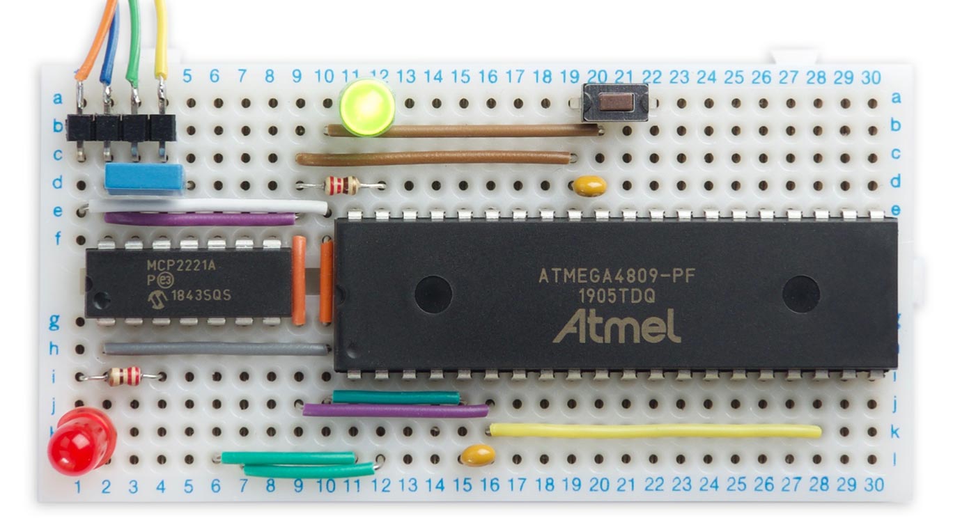
David Johnson-Davies published a new project on his personal blog. He shows us how to build a minimal microcontroller on a breadboard based on the ATmega4809, the microprocessor used in the latest AVR-based Arduino boards. It includes a USB-to-serial converter so you can connect it to your computer’s USB port and program it from the Arduino IDE. He writes:
Arduino’s successors to their classic Arduino Uno board are the Arduino Nano Every [1] and the Arduino Uno WiFi Rev2 [2]. These are based on the ATmega4809 [3], one of Microchip’s AVR processors from their new 0-series ATmega range. As well as having more program memory and RAM than the Arduino Uno’s ATmega328P, the ATmega4809 has some interesting new features, including a 20MHz clock, an event system, and configurable custom logic.
One of the attractions of the old ATmega328P was that it was available in a DIP package, making it ideal for prototyping. Microchip’s latest range of AVR processors aren’t available in DIP packages, with one exception: the ATmega4809 [4]. Coupled with their MCP2221 USB-to-serial chip, which is also available in a DIP package [5], you can make a complete microcontroller on a breadboard that connects straight to a USB port, and can be programmed from the Arduino IDE just like other Arduino boards.
Although you can program an ATmega4809 chip directly, via UPDI, for developing programs it’s much more convenient to install a bootloader, and then program via the serial interface. This has the added benefit that you can use the Arduino Serial Monitor for reading input and printing out values while debugging.
I describe two alternatives here; using an FTDI USB-to-serial converter board, and using an MCP2221A USB-to-serial chip.
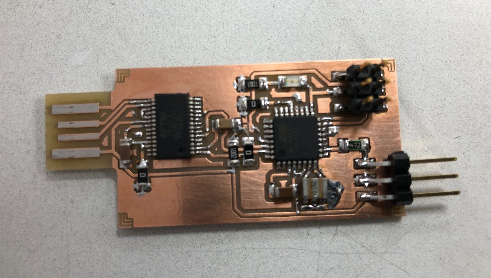
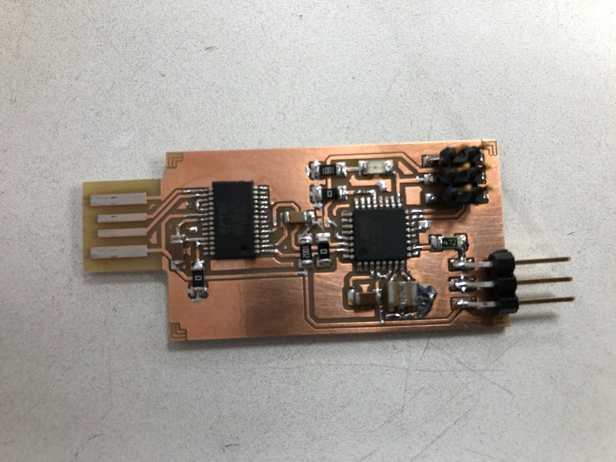
Antti Mäntyniemi designed this board, which is a UPDI programmer that utilizes Arduino IDE to program AVR microcontrollers. This kind of programmer is used to programm the new 0-series and 1-series ATtiny mcus using Arduino IDE.
The project files are available on github.com so you can build your own programmer.
Many of our clients face a common challenge when undertaking IoT projects. They are experts in their own fields, and most of of them have a great idea, a proof-of-concept (PoC), or a sophisticated algorithm that addresses some specific need. They have simulated their solution in Matlab or Python and are eager to build and test a minimum viable product (MVP).
Unfortunately, designing a physical IoT device – or even prototyping one – is no easy task. Our experience has demonstrated that designers have a genuine need for a common, extensible, user-friendly, open source IoT platform that facilitates seamless interaction between the physical and the digital. Which is where we come in.
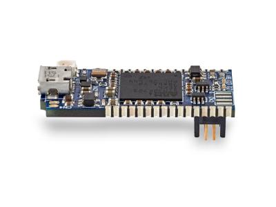
Our primary focus is on products and projects that sample motion, sense the physical world, and transmit the resulting data over Bluetooth Low-Energy (BLE) to smart devices running Android, iOS, Windows, and Linux. We created Bluetera I by stitching together key functionality, including communication hardware and basic motion sensing algorithms, as a way to provide the missing IoT platform our clients needed.
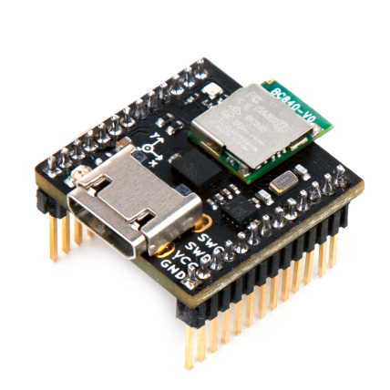
Bluetera II is the full realization of this same objective. It is open hardware running open firmware that includes motion sensors, power management, communication, and user-facing software – all woven together into a robust infrastructure for rapid IoT prototyping.
Bluetera II Demos
The demos in the video above were created primarily using the Windows-WPF application shown below. (You can find source code for this and other demos in our GitHub repository.)
Features
Hardware – A tiny (18 x 18 mm) device with 9-axis motion sensors, an ARM MCU with BLE, battery charging circuitry, and multi-purpose IOs for externals sensors and peripherals
Firmware – Open source infrastructure with embedded command and control, motion algorithms with built-in data exchange and IMU control, a BLE stack with an additional Protobuf abstraction layer, power management, and battery monitoring
Open Source – Everything, from hardware to firmware to the software running on your mobile device or PC is strictly open-source. No strings attached
Motion – 9-axis motion fusion based on the Madgwick Algorithm, which produces rotation data (quaternions) from the 6-axis InvenSense IMU and STM compass. The result is a stable, 1 kHz stream of rotation measurements and raw data.
Google Protobuf – A communication abstraction layer that provides a simple yet flexible serial pipe between the physical layer (e.g. sensors) and the digital layer (e.g. your mobile device). Protobuf makes adding new messages and functionality as easy as 1-2-3.
Power – A JST socket, a Micro USB connector, battery charging circuitry, and power management firmware allow you to power the device with any small, external Lithium-Ion battery.
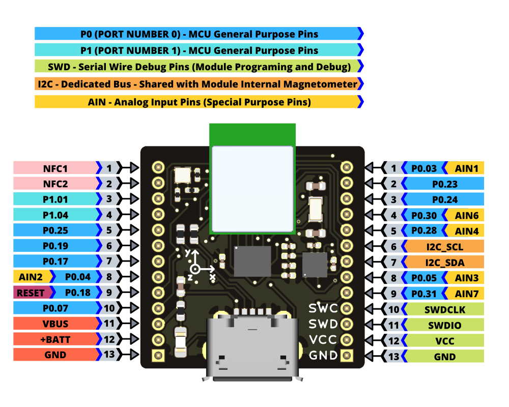
Extensions – 20 I/Os to support digital and analog peripherals and sensors, I²C, SPI, UART, PWM, and more.
USB Type 2 – A Micro USB connector and firmware support for the USB 2 protocol enable fast, wired communication with the host and allow Bluetera II to serve as a BLE dongle.
Rapid Development – A breadboard connected to the tiny Bluetera II provides a standard development matrix and facilitates quick and easy prototyping and debugging with external sensors and peripherals.
SDK – Simplifies software development, with support for multiple operating systems and platforms, includes APIs, algorithms, and demos. The Bluetera II SDK is compatible with Linux, Android, iOS, and Windows. It also includes a plugin for the Unity 3D development platform.
More information is available on the crowd supply and the product page. Further information about the module schematics, SDK, the firmware is available in their GitHub repository.
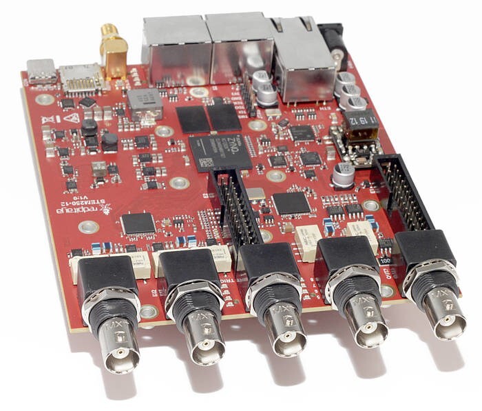
Red Pitaya has launched a high-end STEMlab platform – STEMlab is a test and measurement environment designed to provide a low-cost alternative to many expensive measurement and control instruments. STEMlab 250-12 offers enhanced hardware performance, complete software control and additional hardware features over STEMlab-125 products, and is designed to meet the needs of more demanding users for industrial, research, test & measurement and data acquisition applications. Its larger FPGA enables greater real-time processing capabilities, plus faster analogue front and back-end performance. Small and portable, it also offers the benefits of remote access, with a web app user interface accessible through Ethernet or WiFi.
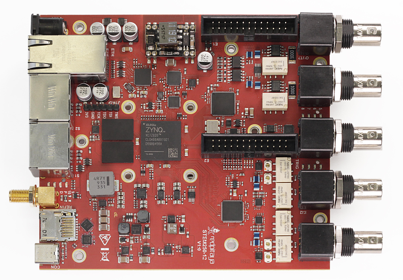
The new STEMlab 250-12 is a two-channel, 250 Msps 12-bit signal acquisition and two-channel 250 Msps 14-bit signal generator module with Zynq 7020 Dual-Core Arm Cortex-A9 CPU and FPGA, 1GB DDR memory and 1Gbit Ethernet connectivity. Accuracy and quality of signal is assured with 12-bit A/D converter resolution, frequency response of ±0.5 dB up to 45MHz and -3dB at 60MHz and channel isolation >60 dB (DC to 100MHz). There are two input ranges of ±1V and ±20V. Outputs can generate signals ranging from DC to 60MHz frequency, with output voltage ranging from ±5V for a 50O load to±10V for high impedance loads.
STEMlab 250-12
The device also features software control for attenuators, gain and trigger level. There is one trigger input via a BNC connector on the front panel and one reference clock input (10MHz) via an SMA connector on the back panel. Signal capture is fast, with rise/fall time of 13ns input 1/20 and 11ns input 1/1. A range of interfaces that are becoming established as standard interfaces across the STEMlab product range are included on STEMlab 250-12, including USB, SPI, I2C and 16 GPIOs. The device also boasts four additional slow analogue inputs and outputs. PoE is offered on request.
Leon Živec, CEO of Red Pitaya, had this to say:
“The addition of the STEMlab 250-12 builds on our successful, open-source STEMlab range by offering high performance signal capture and analysis, with remote access, at an affordable price point. It can be used as an oscilloscope, spectrum analyser and logic analyser with more applications to be released in future, and extends the Red Pitaya user community to include more demanding users, who can use it as an as an alternative to individual, expensive dedicated instruments.”
Piconomix, the South-Africa based Embedded systems development company, has launched a campaign on Crowdsupply for a new board called; PX-Hero.
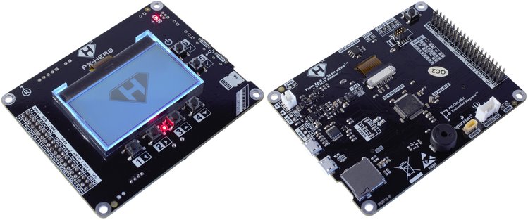
The PX-Her0 is a low-power ARM Cortex MO+ based development board that was developed for use in embedded education applications. The board comes with an ecosystem of tools including an open-source C library, and detailed documentation that is designed to serve as a hands-on guide to help users learn embedded system development at their own pace.
The board is based on the STM32L072RB ultra-low-power, ARM Cortex-M0+ microcontroller with 128kb of FLASH and 4Mbit of serial flash memory using the Adesto AT25SF041 chip, in addition to a spring-loaded microSD card slot which can be used for storage. Showing clear considerations of the need of most beginners, the board comes with a Low-power 128 x 64 monochrome graphic LCD which could be used in teaching how to display data on LCDs, and a LiPo battery charger which makes prototyping battery-based projects easy.
Some specifications and features of the board are provided below:
Microcontroller: STM32L072RB ultra-low-power ARM Cortex-M0+
Display active pixel area: 48.6 x 24.9 mm (1.91 x 0.98″) / 54.6 mm (2.15″) diagonal
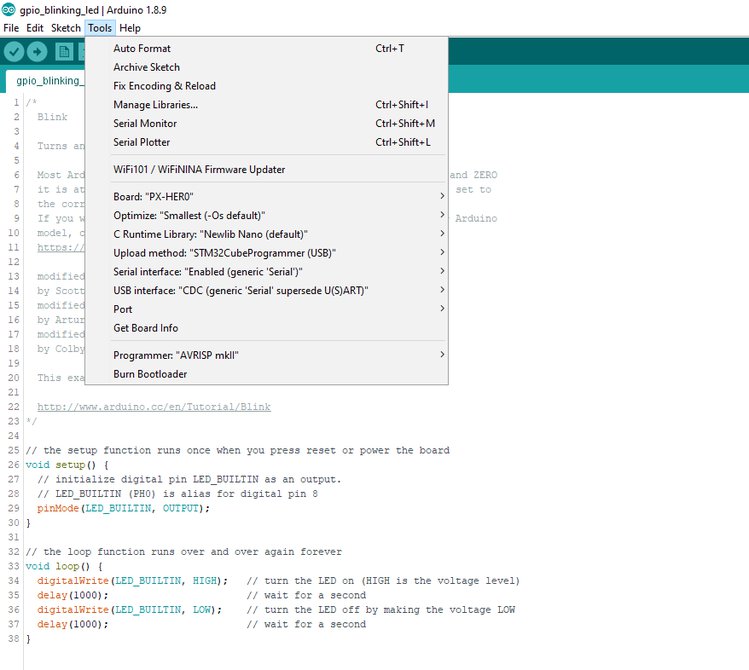
For easy programming, the PX-HERO ecosystem includes a CLI Explorer App (Command Line Interpreter) that creates a “Un*x Shell”-like environment running on the PX-HER0 board so that you can easily experiment with GPIO, PWM, ADC, DAC, I²C, SPI, and 1-Wire using only ANSI/VT100 terminal software. For a more familiar and friendly interface, the PX-HERO is also compatible with the Arduino IDE and native support for it has been added in ArduinoCoreSTM32 version 1.8.0. with the setup process fully documented.
The only downside to the PX-HERO, howbeit, understandable, is the lack of an onboard debugger which according to Piconomix, will increase the board’s power consumption. As such, to provide the fine resolution and insightful view into your firmware, you will need a good in-circuit debugger. To make acquiring the debugger easy and seamless, Piconomix, will be giving backers the opportunity to acquire the STLINK-V3MINI low cost, high-performance in-circuit debugger and programmer for STM32 along with the PX-HERO board.
STLINK-V3MINI Debugger and Programmer
The campaign has raised over $600 so far with close to 36 days to go. It might be a good time to explore it and decide if it’s a good project to back.
More information on the board along with the price and perks can be found on the project’s Crowdsupply page.