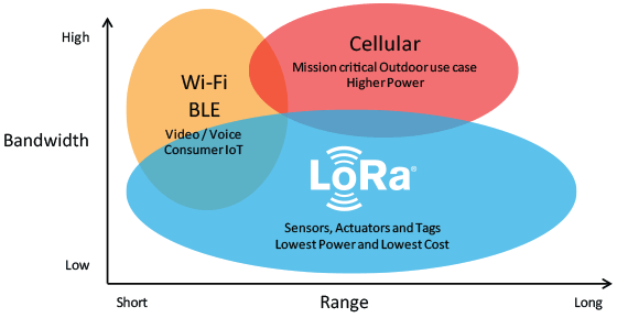
Selecting the right communication protocol is an important part of any IoT project as not being able to communicate with the server/device cloud quickly takes away the “I” in IoT and could lead to the ultimate failure of the project. Several communication protocols exist, from WiFi and Zigbee to 2G, LTE, and even satellite communications, but each of them is usually plagued by one limitation or the other which makes them unsuitable for certain IoT use cases, with the major culprits usually being a tradeoff between range, power, and bandwidth. Semtech, however, demonstrating an understanding the future of IoT, saw a potential game-changer when they acquired France based Cycleo in 2012. Cycleo had developed a patented wireless communication technology called LoRa, which combined ultra-low power consumption with an effective long-range. Semtech leveraged on the power of the community via a consortium and transformed the technology into one of the key drivers of the current wave of digital transformation being instituted by IoT.
Using LoRa technology, devices can typically communicate over a range of 13- 20Km with the ability to go as far as 80KM in certain Line-of-sight setups, and as far as several 100s of KM from outer space as demonstrated by FOSSAT and Lacuna. This range achieved at a very low power which makes LoRa more suitable than other communication protocols, for remote, battery-powered IoT devices that are expected to run for months (or years) on a single battery charge.
LoRa can be deployed in two major ways:
- As a Peer to Peer Communication protocol
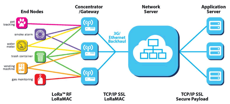
- As a Low Power Wide Area Network
Peer to Peer communication allows two devices with LoRa radios to talk to each other in a manner similar to how two Bluetooth devices communicate, with the major difference being the fact that the range increases massively and less power is consumed.
For deployment as a wide area network, LoRa works hand in hand with Protocols like LoRaWAN which its usually confused with. LoRaWAN is a high capacity, Long Range, open, Low Power Wide Area Network (LPWAN) standard, based on LoRa technology and designed for LoRa Powered IoT Solutions by the LoRa Alliance. The standard takes full advantage of all the features of the LoRa technology to deliver services including reliable message delivery, end to end security, location and multicast capabilities to users while ensuring the interoperability of the various LoRaWAN networks world-wide. This is the standard on which platforms like the things network are built.
While LoRa started with some level of uncertainty, it has grown into the communication means of choice for almost all types of IoT applications, even those who do not benefit from its low power consumption features due to their plugged-in nature. Several advancements like the outer-space based “Gateway” solution being deployed by FOSSAT and Lacuna is making it clear that it will have more impact on IoT than it currently does.
All of these features and advancements make LoRa an important topic for electronics enthusiasts and over the next two tutorials, we are going to build projects to demonstrate how LoRa can be used as the means of communication in your IoT projects. The first tutorial, which we will look today, will focus on using LoRa in a peer-to-peer communication mode, while the second tutorial will focus on LoRa as a Wide Area Network.
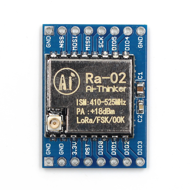
As a demonstration of LoRa being used for pair to pair communication, today’s project will feature two devices, one configured as a transmitter and the other, as a receiver. The transmitter will obtain temperature and humidity sensor from the environment using a DHT11 sensor connected to an Arduino Nano, and forward the data to the receiver via a Ra-02 LoRa module. For the receiver, we will use an ESP8266 Nodemcu development board with another Ra-02 LoRa Module. The temperature and humidity data sent by the transmitter will be received via the Ra-02 module and displayed on the Arduino IDE’s Serial Monitor.
At the end of the tutorial, you would know how to send data between two devices using L0Ra and also how to interface an Arduino and ESP8266 based boards with a LoRa module.
Ready? Let’s go.
Required Components
The following components are required to build this project:
- Arduino Nano
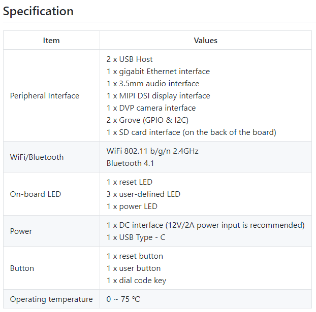
- Ra-02 868mHz LoRa Module x 2
- ESP8266 NodeMCU
- DHT11 Temperature and Humidity Sensor
- 3.7v Lipo/Li-ion battery(Optional)
- Breadboard
- Jumper Wires
All of these components can be bought from the links attached. In place of the Arduino Nano, you can choose to use any other Arduino compatible development board. Just take note on how the change in board type affects other parts of the tutorial. The ESP8266 NodeMCU is also being used because we have a lot of them in stock. Feel free to use any other board. For the Ra-02 LoRa module, take note of the specified frequency when purchasing it to ensure it is legal to use that frequency in your country.
Schematics
As mentioned earlier, there are two sides to today’s project; the transmitter and the receiver, this means we will also have two schematics.
Transmitter Schematics
The transmitter comprises of the DHT11 and the Ra-02 LoRa module connected to the Arduino Nano. The output pin of the DHT11 is connected to a digital pin on the Nano while the Ra-02 is connected to SPI pins of the Nano. Connect the components as shown in the schematics below;
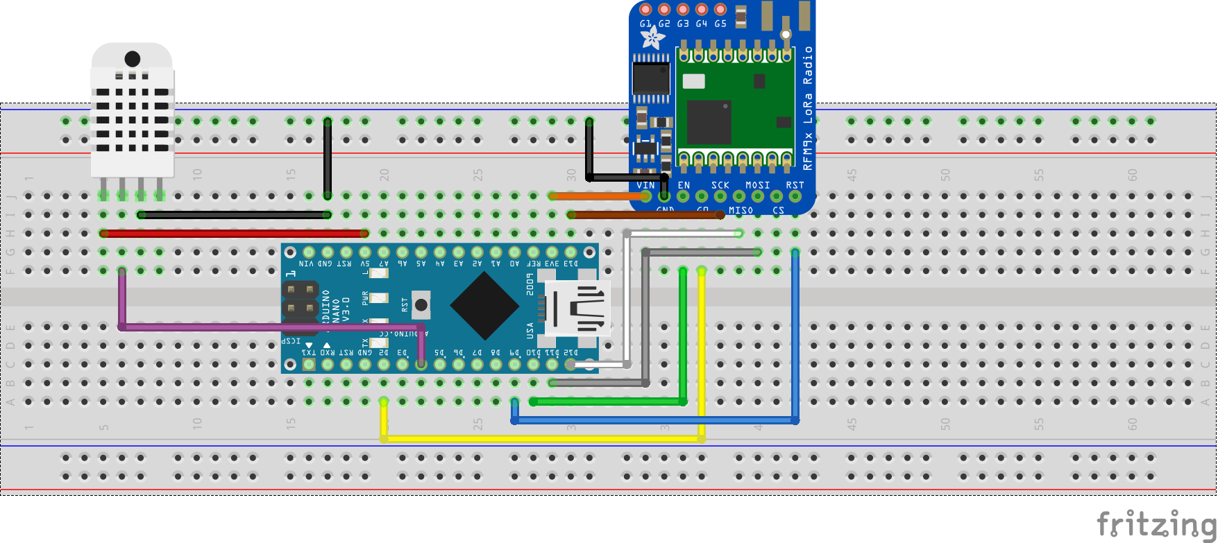
To make the connection easy to follow, a pin-pin description is provided below;
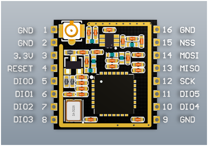
Ra-02 – Arduino Nano
DiO0 - D2
RST - D9
Nss - D10
MOSI - D11
MISO - D12
SCK - D13
GND - GND
3.3V - 3.3V
DHT11 – Arduino Nano
VCC - 5v
GND - GND
D0 - D3
Go over the connections to ensure everything is as it should be before moving to the next section.
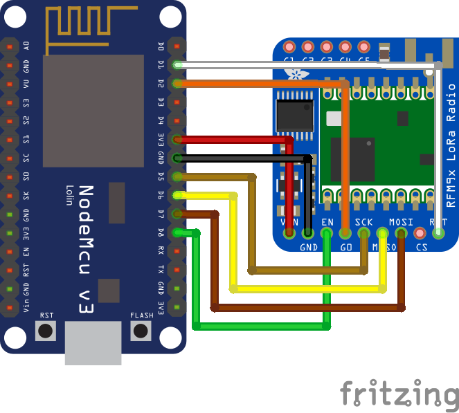
Receiver Schematics
The receiver comprises of the ESP8266 and the Ra-02 LoRa module. Connect them as shown in the schematics below:
To make the connection easy to follow, a pin-pin description is provided below;
Ra-02 – NodeMCU
DiO0 - D2
RST - D1
Nss - D8
MOSI - D7
MISO - D6
SCK - D5
GND - GND
3.3V - 3.3V
Go over the receiver connections also to be sure everything is as it should be.
With both schematics implemented either on a breadboard or on a protoboard, we are now ready to write the code for the project.
Code
As mentioned during the introduction, the goal for today’s project is to send data between two devices (One configured as a transmitter and the other as a receiver) using LoRa. Thus, just like we did with the schematics, we will also split the code into two: Transmitter Code and Receiver Code.
Transmitter Code
The idea behind the code for the transmitter is simple. We obtain the environment’s temperature and humidity data using the DHT11 temperature and humidity sensor and broadcast the data over LoRa to our receiver with an Identity key which ensures the data is only delivered to our receiver.
To reduce the amount of work required to develop the code for our transmitter, we will use a couple of libraries including; the well built LoRa library by Sandeep Mistry along with the DHT library from Adafruit. The LoRa Library comes with a number of functions that make it easy to send and receive data with the LoRa module, while the DHT library makes it easy to interact and extract readings from the DHT11 sensor. Both libraries can be installed via the Arduino Library Manager or downloaded and installed via the links attached to them.
The code for the transmitter is based on the LoRa Sender example located in the LoRa Library, with slight modifications like the addition of a sync word which ensures only the designated receiver with the key receives the message.
To do a quick breakdown of the code, we start by including the libraries that will be used.
#include <SPI.h>
#include <LoRa.h>
#include <DHT.h>
Next, we declare the pins of the Arduino to which the DHT is connected, specify the type of DHT we are using, and create an instance of the DHT library using both parameters.
#define DHTPIN D4                                                           // what digital pin we're connected to
#define DHTTYPE DHT11                                                       // select dht type as DHT 11 or DHT22
DHT dht(DHTPIN, DHTTYPE);
Next, we create a variable called “counter” which will be used to track the number of messages that have been sent to track if it was all delivered or some were lost.
int counter = 0;
With that done, we move to the void setup() function. We start the function by initializing serial communication, so we can use the Serial Monitor for debugging purposes.
void setup() {
  Serial.begin(9600);
  while (!Serial);

  Serial.println("LoRa Sender");
Next, we initialize the DHT as well as the LoRa module specifying the frequency as 868MHz since that is the ISM frequency band supported by my LoRa radio and allowed in my country. If the initialization of the LoRa module fails, the code is suspended in a perpetual while loop, but if successful, we wrap up the void setup() function by setting a unique communication key (Syncword) and also set the power of the Lora radio to the maximum.
  dht.begin();     //initialise DHT11

  if (!LoRa.begin(868E6)) {
    Serial.println("Starting LoRa failed!");
    while (1);
  }
  LoRa.setSyncWord(0xF3);
  LoRa.setTxPower(20);
}
Ensure the frequency you enter corresponds to that of your LoRa module and also be sure it is lawful to use that particular frequency for a project like this.
Up next, is the void loop() function. We start the function by obtaining temperature and humidity data from the environment using the DHT11 and storing them in variable T and H respectively. If the reading fails, we display a fail message and return.
void loop()
{
  float h = dht.readHumidity();
  float t = dht.readTemperature();
  if (isnan(h) || isnan(t)) {
    Serial.println(F("Failed to read from DHT sensor!"));
    return;
  }
Next, we use the LoRa.beginPacket() function to indicate the beginning of a packet, print the temperature and humidity data as part of the packet, along with the counter variable so we can keep track of the messages. then use the LoRa.endPacket() function to indicate the end of the packet and send broadcast it to the receiver.
LoRa.beginPacket();
LoRa.print("Data:");
LoRa.print(counter);
LoRa.print("> ");
LoRa.print("Temperature: ");
LoRa.print(t);
LoRa.print(" ");
LoRa.print("humidity");
LoRa.print(h);
LoRa.endPacket();
Increment the counter and delay for 5000ms to give the module some time before the next data is sent. This goes on and on in the loop() continuously streaming temperature and humidity data from the environment to the LoRa Receiver.
 counter++;

  delay(5000);
}
The complete code for the LoRa transmitter is provided below and also attached under the download section.
#include <SPI.h>
#include <LoRa.h>
#include <DHT.h>
#define DHTPIN D4                                                           // what digital pin we're connected to
#define DHTTYPE DHT11                                                       // select dht type as DHT 11 or DHT22
DHT dht(DHTPIN, DHTTYPE);

int counter = 0;

void setup() {
  Serial.begin(9600);
  while (!Serial);

  Serial.println("LoRa Sender");

  dht.begin();     //initialise DHT11

  if (!LoRa.begin(868E6)) {
    Serial.println("Starting LoRa failed!");
    while (1);
  }
  LoRa.setSyncWord(0xF3);
  LoRa.setTxPower(20);
}

void loop()
{
  float h = dht.readHumidity();
  float t = dht.readTemperature();
  if (isnan(h) || isnan(t)) {
    Serial.println(F("Failed to read from DHT sensor!"));
    return;
  }
  Serial.print("Sending packet: ");
  Serial.println(counter);
  // send packet
  LoRa.beginPacket();
  LoRa.print("Data:");
  LoRa.print(counter);
  LoRa.print("> ");
  LoRa.print("Temperature: ");
  LoRa.print(t);
  LoRa.print(" ");
  LoRa.print("humidity");
  LoRa.print(h);
  LoRa.endPacket();

  counter++;

  delay(5000);
}
Receiver Code
For the receiver, our goal is simply to capture the packet being sent by the transmitter and display it on the serial monitor. To reduce the code complexity, we will use the same LoRa library we used in the transmitter sketch. To do a quick run-through of the code, we start, as always, by including the libraries that will be used.
#include <SPI.h>
#include <LoRa.h>
Next, we define the pins of the Nodemcu to which the NSS, RST and DIO0 pins of the LoRa module are connected. You will notice we didn’t do this for the transmitter sketch? this is because we used the predefined Library’s predefined pins which are usable on the Arduino Nano but not so on the ESP.
//define the pins used by the transceiver module
#define ss D8
#define rst D1
#define dio0 D2
Next, we move to the void setup() function. We start by initializing the serial communication so we can use the Serial Monitor to view incoming data from the receiver.
void setup() {
  //initialize Serial Monitor
  Serial.begin(9600);
  while (!Serial);
  Serial.println("LoRa Receiver");
Next, setup the LoRa module by using the setPins() command to inform the library of the pin configuration to be used.
//setup LoRa transceiver module
LoRa.setPins(ss, rst, dio0);
Next, we initialize LoRa communication with the begin() command. just like we did for the transmitter, ensure that the frequency you use as the argument for the begin() function should be that of your radio and lawful to use it in your country.
//replace the LoRa.begin(---E-) argument with your location's frequency
  //433E6 for Asia
  //866E6 for Europe/Africa
  //915E6 for North America
  if(!LoRa.begin(868E6)) {
    Serial.println(".");
    while (1);
  }
To wrap up the void setup() function, we set the sync word to match that of the transmitter and we print a message on the serial monitor to indicate everything that setup is complete.
   // Change sync word (0xF3) to match the receiver
  // The sync word assures you don't get LoRa messages from other LoRa transceivers
  // ranges from 0-0xFF
  LoRa.setSyncWord(0xF3);
  Serial.println("LoRa Initializing Complete!");
}
Next, we write the loop() function. We start the function by creating a variable to hold the received data and the size of the packet received which will be zero/false if no packet is received.
void loop()
{

  String LoRaData;
  int packetSize = LoRa.parsePacket();
Next, we use an “if” statement to check if a packet has been received, if yes, the data is read using the LoRa.readString() function and stored in the variable we created earlier.
if (packetSize)
{
  // received a packet
  Serial.print("Received packet '");

  // read packet
  while (LoRa.available())
  {
    LoRaData = LoRa.readString();
The read data is then displayed on the serial monitor along with the RSSI which is an indication of the signal strength and may be useful for debugging your transmission power.
     Serial.print(LoRaData);
    }

    // print RSSI of packet
    Serial.print("' with RSSI ");
    Serial.println(LoRa.packetRssi());

   }
}
The complete code for the transmitter is provided below and also attached under the download section.
#include <SPI.h>
#include <LoRa.h>

//define the pins used by the transceiver module
#define ss D8
#define rst D1
#define dio0 D2

void setup() {
  //initialize Serial Monitor
  Serial.begin(9600);
  while (!Serial);
  Serial.println("LoRa Receiver");

  //setup LoRa transceiver module
  LoRa.setPins(ss, rst, dio0);

  //replace the LoRa.begin(---E-) argument with your location's frequency
  //433E6 for Asia
  //866E6 for Europe/Africa
  //915E6 for North America
  if(!LoRa.begin(868E6)) {
    Serial.println(".");
    while (1);
  }
   // Change sync word (0xF3) to match the receiver
  // The sync word assures you don't get LoRa messages from other LoRa transceivers
  // ranges from 0-0xFF
  LoRa.setSyncWord(0xF3);
  Serial.println("LoRa Initializing OK!");
}

void loop()
{

  String LoRaData;
  int packetSize = LoRa.parsePacket();
  if (packetSize)
  {
    // received a packet
    Serial.print("Received packet '");

    // read packet
    while (LoRa.available())
    {
      LoRaData = LoRa.readString();
      Serial.print(LoRaData);
    }

    // print RSSI of packet
    Serial.print("' with RSSI ");
    Serial.println(LoRa.packetRssi());

   }
}
Demo
Connect the Arduino Nano to your computer and upload the transmitter sketch to it. Ensure to select the right board type and comport before uploading. After that, connect the Nodemcu too and upload the receiver sketch to it. Ensure to also switch the board type and select the right com port.
After uploading the sketches, you can decide to leave both devices connected to your computer or disconnect the transmitter device and power it using a power bank or battery leaving just the receiver. With the receiver still connected to your computer, open the serial monitor. You should see the temperature and humidity data from the transmitter being displayed on the Serial Monitor.
That’s it!
While today’s tutorial was a demonstration of peer-peer LoRa communication, the main joy of IoT is when you can get the data to server/device cloud and perform analysis that could lead to the extraction of value-adding insights as such, we will create a second part to this tutorial which will show how to get the data being received to the cloud.