Network Clock using ESP8266 and OLED display

There are several situations where using an RTC could adversely affect your project by increasing cost, size, time accuracy or IO requirements. To prevent this, especially in ESP/WiFi-based or other clock-reliant projects, makers usually turn to obtain time information from NTP servers. I recently came across a project by BitsandBlobs which used standalone NTP Servers and I felt it might be one of the best ways to introduce to this concept. So for today’s tutorial, we will build an NTP Based Network Time Clock based on “BitsandBlobs” build.

NTP (Network Time Protocol) is an internet protocol used for synchronizing clocks on computer networks within a few milliseconds of universal coordinated time (UTC). Using this protocol, devices can request and receive UTC data from an NTP server which usually receives precise time from an atomic clock.

The WiFi capabilities of the ESP8266 based Wemos D1 mini will be used in obtaining time information from a public NTP server and it will be displayed in a user-friendly manner on an OLED display.

At the end of this project, you would know not only how to obtain time information from NTP servers, but also how to use the WemosD1 for your WiFi projects.

Required Components

The following components are required to build this project:

  1. Wemos D1 Mini
  2. 0.96″ I2C OLED Display
  3. Jumper Wires
  4. BreadBoard (Optional)

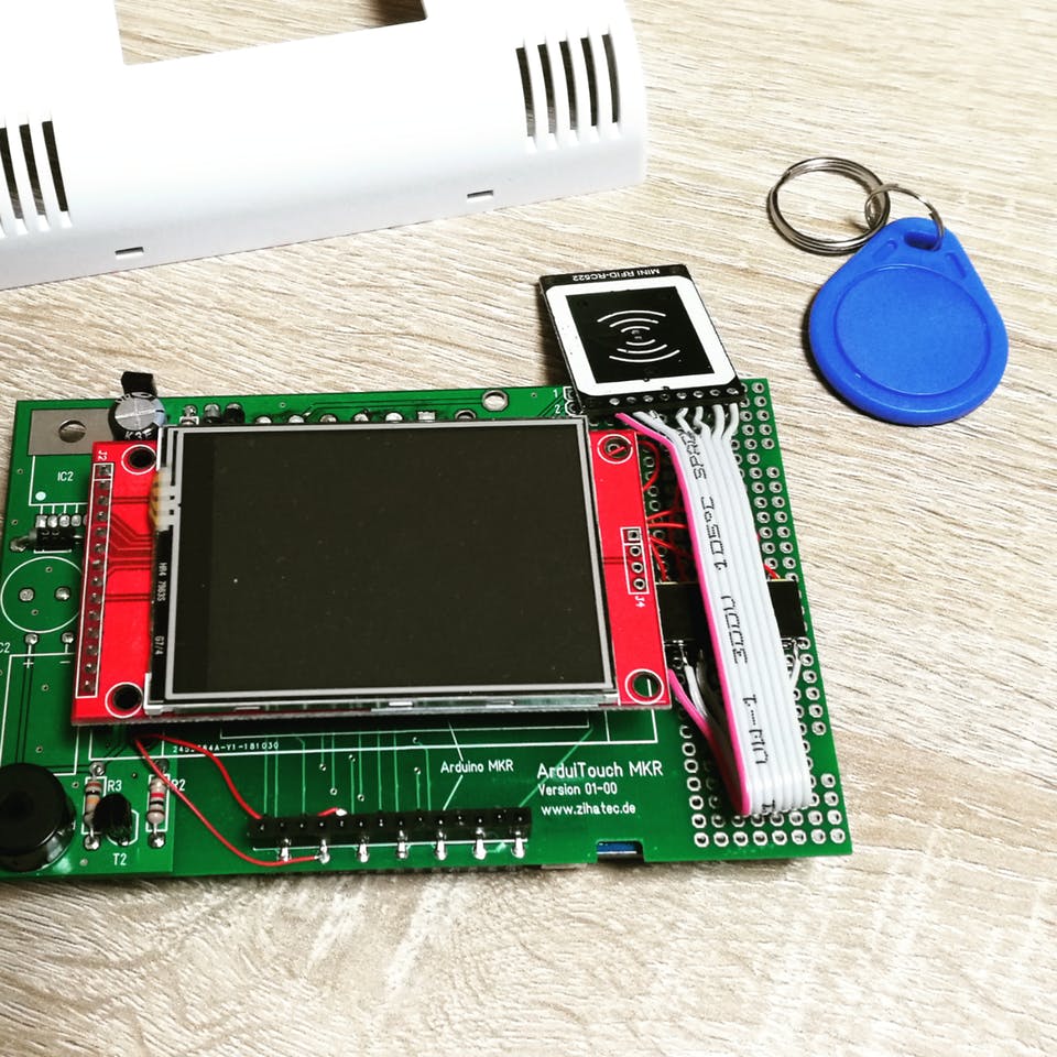
The components can be purchased from the attached links. While an interesting enclosure was built for this project, for those who don’t have access to a 3D printer and don’t want to solder the components, you can go for the option of implementing the project on a breadboard.
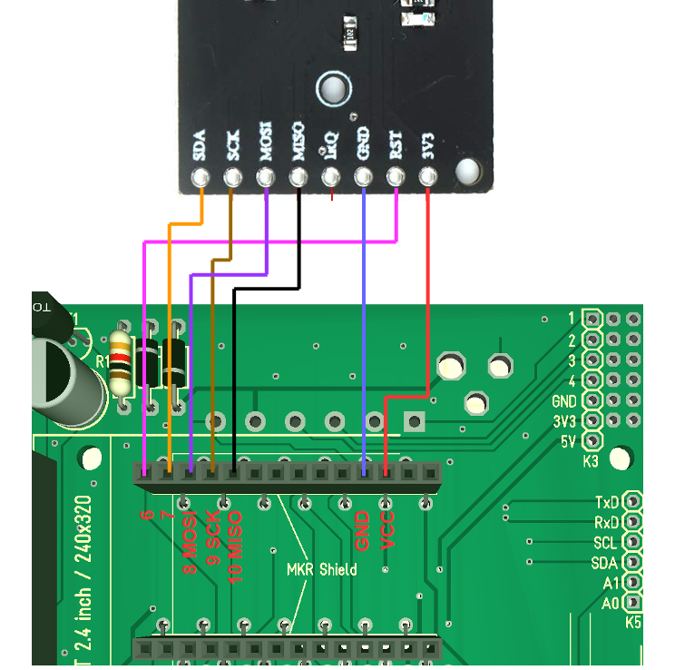
Schematics

Thanks to the use of just two components, the schematics for today’s project is super straightforward. The OLED display being used communicates with the host microcontroller via I2C as such all we need do is connect the display to the I2C pins of the Wemos D1 mini as shown in the schematics below:

Schematics (Credits: BitsandBlobs)

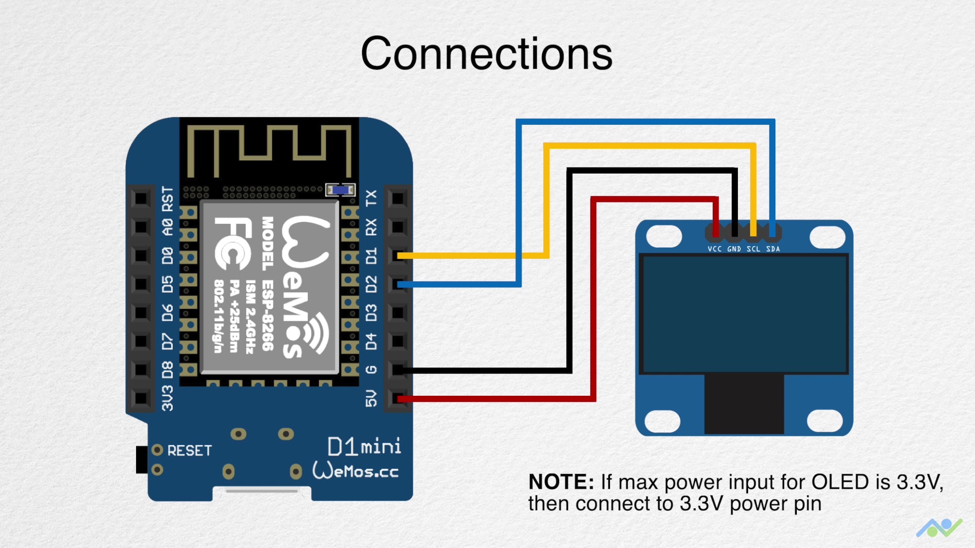
To make the connections easier to follow, a pin-pin map is provided below:

Wemos D1 – OLED

D1 - SCL
D2 - SDA
5v - VCC
GND - GND

It is important to note the maximum input voltage of your OLED display and be sure it is 5V tolerant. You should connect the VCC pin of the OLED to the Wemos D1’s 3.3v pin if 5V is too high for the display.

With the schematics complete, we can now proceed to the code for the project.

Code

The Arduino IDE is used for the code developing of this project, as such, if this is the first time are using an ESP8266 based board with the IDE, you will need to install the ESP8266 support for it. Follow this tutorial we wrote a while back on “Programming an ESP8266 Board with the Arduino IDE” to get it done.

The algorithm behind the code for today’s project is quite straightforward. We start by connecting the Wemos D1 to the internet via a WiFi Access point and access an NTP server to obtain the network time. We convert network time to our local time equivalent and display the local time on the OLED display.

To make writing the code easier, we will use some libraries including; the ESP8266WIFI library, the Time library, and the U8g2 library.  The ESP8266WIFI library is used for everything related to connecting the Wemos to the internet through a WiFi access point, while the Time Library has function implementations that enable us easily extract time from NTP servers, and the U8g2 library allows us to interact with the OLED and display text on it in fancy fonts. The ESP8266WiFi and Time library comes pre-installed with the ESP8266 Arduino IDE support while the U8g2 library will need to be installed via the Arduino Library Manager or by downloading from the link attached above.

With the libraries installed, we are now ready to go over the code. As usual, I will do a quick run through it and try to explain some of the concepts in it that might be difficult to follow.

We start as usual by including all the libraries that we will use.

#include <ESP8266WiFi.h>
#include <time.h>
#include <U8x8lib.h>

Next, we provide the credentials (SSID and Password) of the WiFi access point through which the Wemos will access the internet and also specify the address of the NTP server we will connect to along with the timezone string which is used to correct the clock from the NTP server and to match that of our timezone. Since time zones are different, and the clock will not be correct if you don’t augment it with the time zone string, you might need to visit Remote Monitoring System’s website to get the correct time zone string (TZ_INFO) for your particular location.

const char* ssid = "Access point's SSID";              
const char* password = "Access point's PASSWORD";      

const char* NTP_SERVER = "ch.pool.ntp.org";
const char* TZ_INFO    = "GMT+0BST-1,M3.5.0/01:00:00,M10.5.0/02:00:00";  // enter your time zone (https://remotemonitoringsystems.ca/time-zone-abbreviations.php)

Next, we declare a few important variables that will be used to store data during the program run and create an instance of the U8g2 library with the pins of the Wemos D1 to which the OLED is connected, as arguments.

tm timeinfo;
time_t now;
long unsigned lastNTPtime;
unsigned long lastEntryTime;

U8X8_SSD1306_128X64_NONAME_SW_I2C u8x8(/* clock=*/ SCL, /* data=*/ SDA, /* reset=*/ U8X8_PIN_NONE);   // OLEDs without Reset of the Display

Next is the void setup() function. We start the function by initializing the OLED display and Serial communication with a baud rate of 115200.

void setup() 
{
  u8x8.begin();
  
  Serial.begin(115200);
  Serial.println("\n\nNTP Time Test\n");

Next, we connect the Wemos to the WiFI access point using the WiFi.begin() function with the credentials of the access point as arguments. The program is stalled in a perpetual loop till the Wemos has connected successfully to the access point.

WiFi.begin(ssid, password);

  Serial.print("Connecting to network");
  int counter = 0;
  while (WiFi.status() != WL_CONNECTED) 
  {
    delay(200);    
    if (++counter > 100) 
      ESP.restart();
    Serial.print( "." );
  }
  Serial.println("\nWiFi connected\n\n");

Next, we use the configtime() function to initialize a connection with the NTP server and use the setenv() function to set the time zone. Timezone codes for different regions can be also be obtained from Nayarsystems github page.

configTime(0, 0, NTP_SERVER);
 // See https://github.com/nayarsystems/posix_tz_db/blob/master/zones.csv for Timezone codes for your region
 setenv("TZ", TZ_INFO, 1);

With that done, we then make attempts to sync the NodeMCU with the NTP server using the getNTPtime() function. If the sync is not successful, the ESP is restarted, but if successful, the current time from the NTP server is saved as the NTP time and millis() is kickstarted so the time can be tracked and updated locally.

if (getNTPtime(10)) 
  {  
    // wait up to 10sec to sync
  } 
  else 
  {
    Serial.println("Time not set");
    ESP.restart();
  }
  showTime(&timeinfo);
  lastNTPtime = time(&now);
  lastEntryTime = millis();
}

Next, we move to the void loop() function.

The loop() function is quite straight forward. We simply get the time from the time using the getNTPtime() function and display it on the OLED with the showTime(&timeinfo) function. A delay of 1000ms is added to the code to ensure the text is displayed smoothly.

void loop() 
{
  getNTPtime(10);
  showTime(&timeinfo);
  delay(1000);
}

The two key functions driving behind the code for the project are the getNTPtime() and the showTime() functions.

The getNTPtime uses the millis() function to keep track of the last time received from the NTP server and update the current time based on it. The time and date information are obtained from the data received from the NTP server and the “timeinfo” variable is updated with that data.

bool getNTPtime(int sec) 
{
  {
    uint32_t start = millis();
    do
    {
      time(&now);
      localtime_r(&now, &timeinfo);
      delay(10);
    } while (((millis() - start) <= (1000 * sec)) && (timeinfo.tm_year < (2016 - 1900)));
    
    if (timeinfo.tm_year <= (2016 - 1900)) 
        return false;  // the NTP call was not successful
    
    Serial.print("Time Now: ");  
    Serial.println(now); 
  }
  return true;
}

The showtime() function, on the other hand, splits up the timeinfo variable and displays the time information including the date, day of the week, and clock, on the OLED display, as well as the serial monitor.

void showTime(tm *localTime) 
{
  //print to serial terminal
  Serial.print(localTime->tm_mday);
  Serial.print('/');
  Serial.print(localTime->tm_mon + 1);
  Serial.print('/');
  Serial.print(localTime->tm_year - 100);
  Serial.print('-');
  Serial.print(localTime->tm_hour);
  Serial.print(':');
  Serial.print(localTime->tm_min);
  Serial.print(':');
  Serial.print(localTime->tm_sec);
  Serial.print(" Day of Week ");
  Serial.println(localTime->tm_wday);
  Serial.println();

  //display on OLED
  char time_output[30];
  
  u8x8.setFont(u8x8_font_courB18_2x3_f);
  u8x8.setCursor(0,0);
  sprintf(time_output, "%02d:%02d:%02d", localTime->tm_hour, localTime->tm_min, localTime->tm_sec);
  u8x8.print(time_output);
  
  u8x8.setFont(u8x8_font_8x13B_1x2_f);
  u8x8.setCursor(4,4);
  sprintf(time_output, "%02d/%02d/%02d", localTime->tm_mday, localTime->tm_mon + 1, localTime->tm_year - 100);
  u8x8.print(time_output);
  
  u8x8.setCursor(4,6);
  u8x8.print(getDOW(localTime->tm_wday));
}

The last function in the sketch is the getDOW() function which is used to convert the numeric day of the week value from the time struct, into a String(the name value).

char * getDOW(uint8_t tm_wday)
{
  switch(tm_wday)
  {
    case 1:
      return "Monday";
      break;

    case 2:
      return "Tuesday";
      break;

    case 3:
      return "Wednesday";
      break;

    case 4:
      return "Thursday";
      break;

    case 5:
      return "Friday";
      break;

    case 6:
      return "Saturday";
      break;

    case 7:
      return "Sunday";
      break;

    default:
      return "Error";
      break;
  }
}

The complete code for the project is provided below and also attached in the zip file under the download section.

#include <ESP8266WiFi.h>
#include <time.h>
#include <U8x8lib.h>

const char* ssid = "Access point's SSID";              
const char* password = "Access point's PASSWORD";      

const char* NTP_SERVER = "ch.pool.ntp.org";
const char* TZ_INFO    = "GMT+0BST-1,M3.5.0/01:00:00,M10.5.0/02:00:00";  // enter your time zone (https://remotemonitoringsystems.ca/time-zone-abbreviations.php)

tm timeinfo;
time_t now;
long unsigned lastNTPtime;
unsigned long lastEntryTime;

U8X8_SSD1306_128X64_NONAME_SW_I2C u8x8(/* clock=*/ SCL, /* data=*/ SDA, /* reset=*/ U8X8_PIN_NONE);   // OLEDs without Reset of the Display

void setup() 
{
  u8x8.begin();
  
  Serial.begin(115200);
  Serial.println("\n\nNTP Time Test\n");
  WiFi.begin(ssid, password);

  Serial.print("Connecting to network");
  int counter = 0;
  while (WiFi.status() != WL_CONNECTED) 
  {
    delay(200);    
    if (++counter > 100) 
      ESP.restart();
    Serial.print( "." );
  }
  Serial.println("\nWiFi connected\n\n");

  configTime(0, 0, NTP_SERVER);
  // See https://github.com/nayarsystems/posix_tz_db/blob/master/zones.csv for Timezone codes for your region
  setenv("TZ", TZ_INFO, 1);

  if (getNTPtime(10)) 
  {  
    // wait up to 10sec to sync
  } 
  else 
  {
    Serial.println("Time not set");
    ESP.restart();
  }
  showTime(&timeinfo);
  lastNTPtime = time(&now);
  lastEntryTime = millis();
}

void loop() 
{
  getNTPtime(10);
  showTime(&timeinfo);
  delay(1000);
}

bool getNTPtime(int sec) 
{
  {
    uint32_t start = millis();
    do
    {
      time(&now);
      localtime_r(&now, &timeinfo);
      delay(10);
    } while (((millis() - start) <= (1000 * sec)) && (timeinfo.tm_year < (2016 - 1900)));
    
    if (timeinfo.tm_year <= (2016 - 1900)) 
        return false;  // the NTP call was not successful
    
    Serial.print("Time Now: ");  
    Serial.println(now); 
  }
  return true;
}

void showTime(tm *localTime) 
{
  //print to serial terminal
  Serial.print(localTime->tm_mday);
  Serial.print('/');
  Serial.print(localTime->tm_mon + 1);
  Serial.print('/');
  Serial.print(localTime->tm_year - 100);
  Serial.print('-');
  Serial.print(localTime->tm_hour);
  Serial.print(':');
  Serial.print(localTime->tm_min);
  Serial.print(':');
  Serial.print(localTime->tm_sec);
  Serial.print(" Day of Week ");
  Serial.println(localTime->tm_wday);
  Serial.println();

  //display on OLED
  char time_output[30];
  
  u8x8.setFont(u8x8_font_courB18_2x3_f);
  u8x8.setCursor(0,0);
  sprintf(time_output, "%02d:%02d:%02d", localTime->tm_hour, localTime->tm_min, localTime->tm_sec);
  u8x8.print(time_output);
  
  u8x8.setFont(u8x8_font_8x13B_1x2_f);
  u8x8.setCursor(4,4);
  sprintf(time_output, "%02d/%02d/%02d", localTime->tm_mday, localTime->tm_mon + 1, localTime->tm_year - 100);
  u8x8.print(time_output);
  
  u8x8.setCursor(4,6);
  u8x8.print(getDOW(localTime->tm_wday));
}

char * getDOW(uint8_t tm_wday)
{
  switch(tm_wday)
  {
    case 1:
      return "Monday";
      break;

    case 2:
      return "Tuesday";
      break;

    case 3:
      return "Wednesday";
      break;

    case 4:
      return "Thursday";
      break;

    case 5:
      return "Friday";
      break;

    case 6:
      return "Saturday";
      break;

    case 7:
      return "Sunday";
      break;

    default:
      return "Error";
      break;
  }
}

Demo

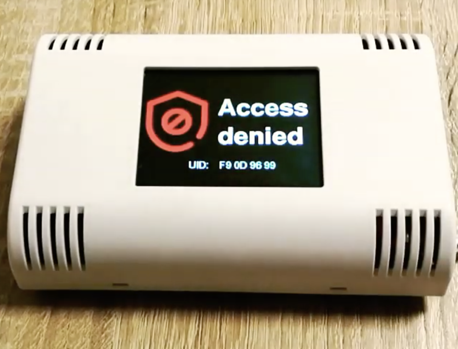
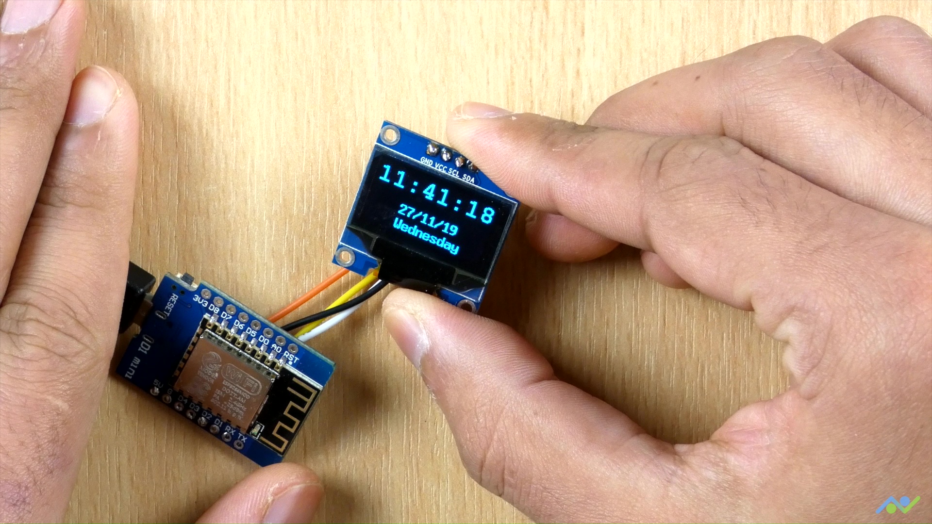
Go over the connections again and ensure you have the ESP8266’s Arduino IDE board support package installed along with the U8g2 library.  Once confirmed, connect the Wemos D1 to your computer and select it in the Arduino IDE along with the port to which it is connected. Hit the upload button and wait for the completion of the upload process. When Completed, you should see the time and date information is displayed on the OLED as shown in the image below.

The clock is working (Credits: BitsandBlobs)

Going Further

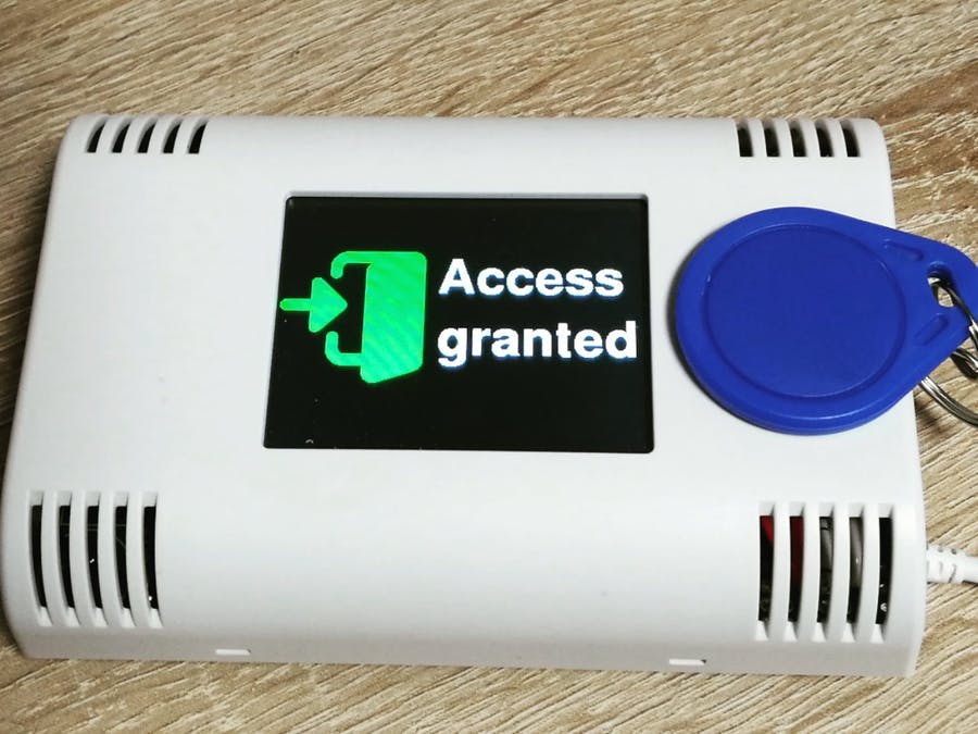
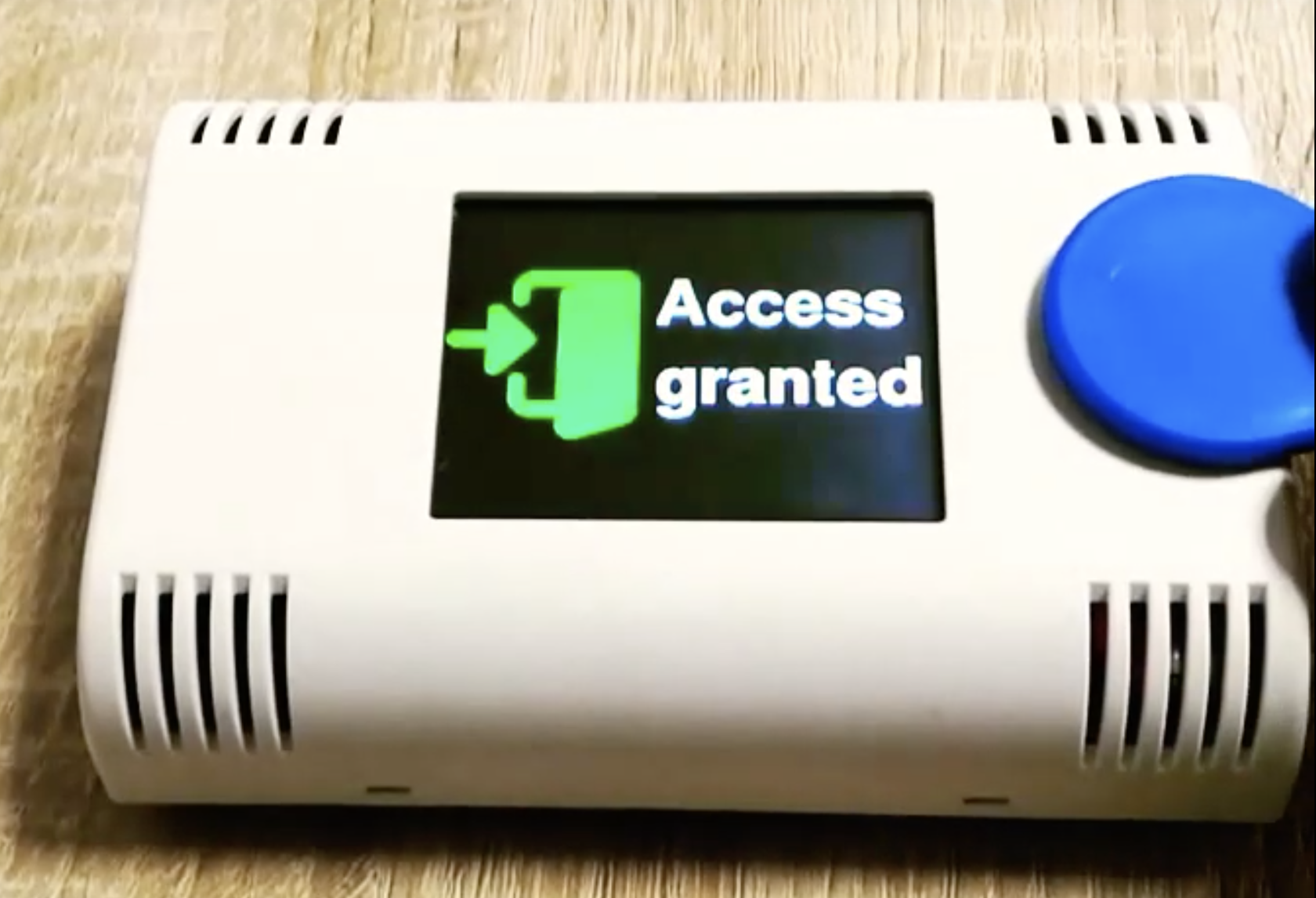
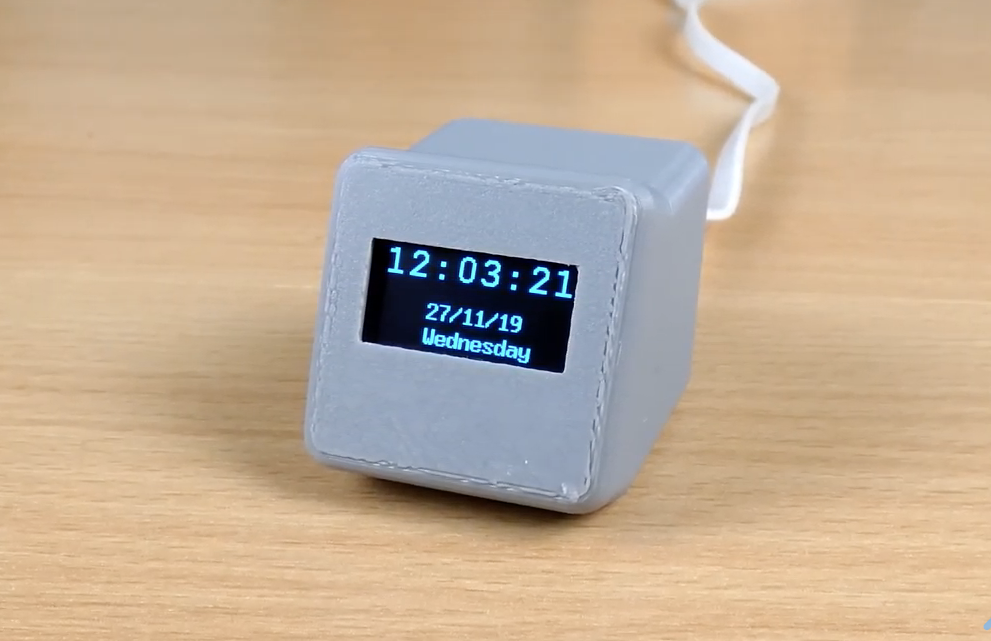
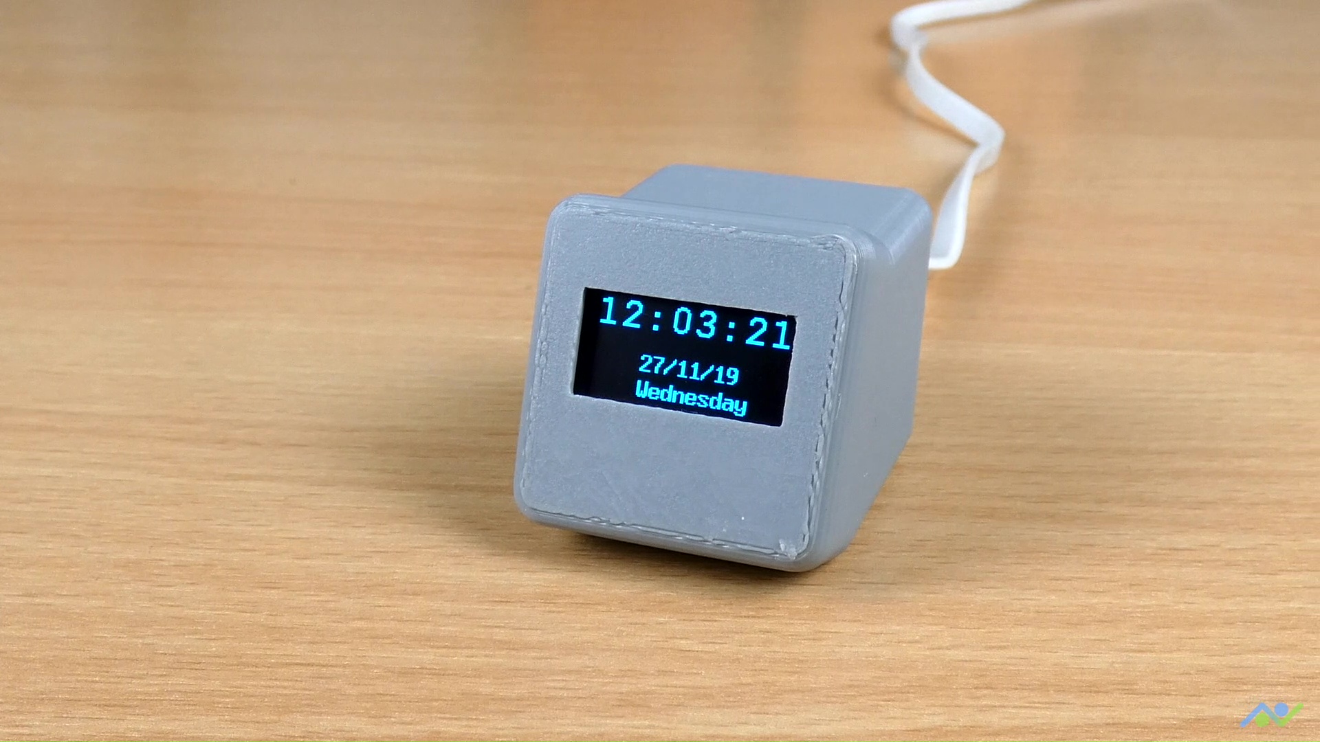
To take things further, one of the quick things you can do is hook up the device into the 3D printed enclosure designed by “BitsandBlobs”. The design and assembly instructions are available on Thingiverse, so all you need to do is to download and print it. After putting it in the 3D printed enclosure, the clock looks like the image below.

Demo with Enclosure (Credit: BitsandBlobs)

That’s it for this tutorial, thanks for reading. Do let me know via the comment section if you built one of these and also let me know if you have any challenges replicating them.

Arduino RFID Reader using the ArduiTouch MKR Enclosure

RFID Access Control System

RFID based projects are one of the most popular Arduino projects out there and we have also built a couple of them here too, but I recently came across an RFID access control project by hwhardsoft that was built using the ArduiTouch MKR enclosures. The ready-made nature of the enclosures and their existence for different kinds of boards caught my attention and I felt it might be of interest to most readers here too.  So for today’s project, we will build an RFID based Access Control system using the ArduiTouch MKR enclosure, an Arduino MKR WiFi 1010 and an InnovateKing-EU RFID reader.

The ArduiTouch series of enclosures come with a display already fitted on a PCB specifically designed for a specific family of maker board. The best way to describe them will be “evaluation boards with screens and enclosures for maker boards”. The ArduiTouch MKR enclosure to be used today, was designed for the Arduino MKR family of boards and it comes with; an 120 x 80 x 33 mm enclosure for top wall mounting, a 2.4-inch resistive touch TFT, an integrated voltage regulator, an integrated piezo beeper, breadboard area for easy mounting of components, and a slot for an MKR shield.

All of the above features make it easy to create a very nice looking RFID reader, with TFT output for wall/door mounting with an Arduino MKR of your choice. The Arduino MKR of choice selected for this tutorial is the Arduino MKR WiFi 1010, and the RFID module selected is the InnovateKing-EU RFID Reader.

At the end of today’s tutorial, you would know not only how to build a fancy RFID reader but also the intricacies of working with an ArduiTouch MKR Enclosure and using the InnovateKing-EU RFID Reader.

Arduino RFID Reader using the ArduiTouch MKR Enclosure – [Link]

Realtek8720DN 2.4G/5G Dual Bands Wireless and BLE5.0 Combo Module

Realtek8720DN is a WiFi and Bluetooth module that has dual bands for WiFi communication. It is worth saying that this little module can support WiFi 5G and Bluetooth Low Energy 5.0 as well. This WiFi and Bluetooth module is a highly integrated WiFi and Bluetooth module with the main chip RTL8720DM, it can be regarded as an SoC for the WiFi and Bluetooth application with typical SBCs.

Except for the main chip, the Realtek8720DN module consists of a high-performance MCU named KM4, a low power MCU named KM0, WLAN (802.11 a/b/g/n) MAC, a 1T1R capable WLAN baseband, RF, Bluetooth, and peripherals. An inner antenna and many interfaces are available in this little WiFi and Bluetooth module.

Key Features

  • WiFi and Bluetooth module.
  • Support both WiFi 2.4G and WiFi 5G with protocol 802.11 a/b/g/n 1×1 from 20/40 MHz up to MCS7.
  • Support WiFi low power mode.
  • Support Bluetooth (BLE) 5.0.

Peripheral Interfaces

  • 1 common ADC interface
  • 2 log UART with standard baud rate support
  • 1 I2C interfaces are shared with the PWM interfaces
  • 1 SPI interfaces are shared with the PWM interfaces
  • 4 PWM interfaces
  • All of the above interfaces can be used as GPIO

Compare with ESP series, this WiFi and Bluetooth module has more functions like 5G WiFi and Bluetooth 5.0. As a matter of fact, this little module can be widely used for more applications than the ESP series.

You can pre-order the module from seeedstudio.com for $3.90

Neousys Technology Launches the POC-551VTC – an AMD RYZEN PC for Transportation

Neousys Technology, the embedded computing platforms manufacturer, has announced plans to launch an ultra-compact, rugged fanless in-vehicle computer called the POC-551VTC. The new computer was designed as an upgrade to the POC-500 embedded computer which the company released a while back and it comes with several I/O ports to serve applications around wireless communication, mobile Surveillance, in-vehicle entertainment, and fleet management to mention a few.

Featuring the same AMD’s Ryzen Embedded V1000 family of x86-based SoC used in the POC-500 with the AMD Ryzen™ Embedded V1605B processor, the POC-551VTC combines two of AMD’s strongest chips, the Zen x86 core architecture with Vega GPU into a small BGA package. Leveraging on 4-cores and 8-threads, POC-551VTC delivers the equivalent processing power of an Intel 6th Gen. Core i7 U-series, coupled with the unprecedented 3.6 TFLOPS in FP16, delivered by the Radeon Vega GPU.

Designed with an understanding of the connected nature which cars are now attaining, the POC-551VTC comes with three full-size mini-PCIe sockets and one M.2 B key with an internal SIM socket for 3G/4G, GPS or WiFi module installation. To ensure seamless connections with little or no dead zones, the device also comes with expansion sockets that allow users to connect to multiple operators, and facilitate a seamless switch from one operator to another.

Four in-vehicle connections and usage, the POC-551VTC comes with; a CAN 2.0 port, four USB 3.1 Gen1 ports, four COM ports, and 4-CH isolated D I/O for data communication between different types of devices. It also comes with 4(four) 802.3at PoE+ ports which are capable of supplying up to 25W of power to connected devices like IP cameras. All ports on the POC-551VTC come with a screw-lock mechanism to ensure cable connections are secure.

All these features are packed into a, quite small 64 x 176 x 116 mm (2.5″ x 6.9″ x 4.6″) form factor, with an enclosure built with Neousys’ proven thermal design. The ruggedized nature of the POC-551VTC ensures its ability to operate at a temperature between -40℃ to 70℃,, and support a wide range input voltage (8~35V DC) with a built-in ignition control, which protects the system with gentle shutdowns.

The POC-551VTC comes with; the E-mark, which means it is certified for in-vehicle deployment, and the EN-50155 and EN-45545-2 certifications for railway fire and smoke safety.

All of these features including the certifications, extraordinary processor performance, numerous I/Os, communication ports, and compact form factors makes the POC-551VTC, deployment-ready for any transportation-related applications.

There is currently no information as regards the price and availability of this device as the product page only had the specs. We will, however, keep a close watch and update the article the moment this information is available.

More information on the Specifications and features of the POC-551VTC can be found on the Neosys’s Website.

Saelig Announces the 2/4-channel 100-350Hz Siglent SDS2000X Plus Series Oscilloscopes

New series builds on previous 2000X models to bring 200Mpt memory, 10” touch-screen, external mouse/keyboard control, built-in web server, and 50MHz waveform generator

Saelig Company, Inc. has introduced the new Siglent SDS2000X Plus Digital Oscilloscope Series consisting of four models: one 2-channel 100MHz bandwidth (software upgradeable to 350MHz) and three 4-channel models (100/200/350MHz.)  The 350MHz models can be upgraded to 500MHz on two independent channels.  A large 10.1” capacitive touch-screen supports multi-touch gestures.  The oscilloscope range also offers a 10-bit acquisition mode that uses oversampling to achieve higher resolution than most scopes. Combined with the lowest vertical setting of 500μV/div, the X Plus series can display extremely small signal details. The 4-channel models all feature dual 2GSa/s ADCs and also dual 200Mpt memory modules. This enhanced memory depth enables a high sample rate at larger time/div settings. This is valuable when analyzing high-frequency content on slowly changing signals by providing the detail needed, regardless of time-base settings.

Siglent SDS2000X Plus Digital Oscilloscope Series

The SDS2000X Plus uses the versatile user interface of the higher performance SDS5000X series. This includes the capabilities of a 10” touch-screen, and external mouse/keyboard control.

With waveform capture rates of up to 120,000 wfms/sec, the sequence mode boosts the capture rate to 500,000wfm/s to ensure the capture of critical events and rare signal anomalies.   A built-in 50MHz function generator is optionally available together with a free Bode plot function to deliver convenient and low cost frequency analysis.  The LAN port supports easy remote control via a built-in webserver using a web-browser or SCPI remote commands.

The X Plus series also features a Power Analysis option for automatic on-screen performance analysis of common power supply characteristics. Siglent’s optional probes for current and differential voltage measurements make a valuable addition for power design applications.  When developing switch-mode power supplies (SMPS), Bode plots are a convenient way to measure the phase and gain margin of feedback loop systems to determine the stability of the design.  This is now easily performed on the SDS2000X Plus series.

The SDS2000X Plus series of oscilloscopes is made by Siglent Technologies, a leading high quality test equipment manufacturer, with a growing worldwide reputation.  This series is available now from Saelig, their USA technical distributor.

Microchip’s Wi-Fi Smart Device Enablement Kit for SAML21MCU – AC164165

Microchip’s Wi-Fi® Smart Device Enablement Kit is designed to accelerate adding Alexa Voice Control to your existing application, enabling rapid prototyping.

The kit allows you to use an Alexa Smart Speaker or the Alexa App to control the board’s GPIO, interrogate its sensors, and change its LED colors. By following our Alexa skill examples, you can create custom Alexa skills to further enhance the operation for your application. For more information please visit the GitHub page HERE

To get started using the Wi-Fi Smart Device Enablement Board, please visit:  www.microchip.com

Arduino RFID Reader using the ArduiTouch MKR Enclosure

RFID based projects are one of the most popular Arduino projects out there and we have also built a couple of them here too, but I recently came across an RFID access control project by hwhardsoft that was built using the ArduiTouch MKR enclosures. The ready-made nature of the enclosures and their existence for different kinds of boards caught my attention and I felt it might be of interest to most readers here too.  So for today’s project, we will build an RFID based Access Control system using the ArduiTouch MKR enclosure, an Arduino MKR WiFi 1010 and an InnovateKing-EU RFID reader.

RFID Access Control System

The ArduiTouch series of enclosures come with a display already fitted on a PCB specifically designed for a specific family of maker board. The best way to describe them will be “evaluation boards with screens and enclosures for maker boards”. The ArduiTouch MKR enclosure to be used today, was designed for the Arduino MKR family of boards and it comes with; an 120 x 80 x 33 mm enclosure for top wall mounting, a 2.4-inch resistive touch TFT, an integrated voltage regulator, an integrated piezo beeper, breadboard area for easy mounting of components, and a slot for an MKR shield.

All of the above features make it easy to create a very nice looking RFID reader, with TFT output for wall/door mounting with an Arduino MKR of your choice. The Arduino MKR of choice selected for this tutorial is the Arduino MKR WiFi 1010, and the RFID module selected is the InnovateKing-EU RFID Reader.

At the end of today’s tutorial, you would know not only how to build a fancy RFID reader but also the intricacies of working with an ArduiTouch MKR Enclosure and using the InnovateKing-EU RFID Reader.

Required Components

The following components are required to build this project:

  1. Arduino MKR WiFi 1010
  2. ArduiTouch MKR
  3. InnovateKing- EU RFID Reader with tags
  4. Jumper Wires

All of these components can be bought via the attached links, and you could choose to go with other versions/types of components like a different Arduino MKR board or a different RFID Reader. Just ensure you take note of the changes that might be introduced into other parts of the project (like schematics and code) as a result of that.

Schematics

As mentioned earlier, today’s project is centered around the ArduiTouch MKR evaluation board. What this means is that we do not need to worry about arranging the components on a breadboard or designing a PCB to make things compact. All we need to do is to connect the components to the right pins on the ArduiTouch MKR PCB and off we go. The display and Arduino MKR WiFi 1010 already have their pins mapped out on the board as such we only need to plug them in, but the InnovateKing-EU RFID Reader needs to be connected to specific pins on the board. The schematics showing how it is connected is provided in the image below;

Schematics

The InnovateKing-EU RFID reader is connected to the SPI pins of the MKR. A pin to pin map describing the connection is provided below:

MKR – InnovateKing-EU Rfid Reader

GND - GND
VCC - 3.3V
D6 - RST
D7(CS) - SDA
D9(SCK) - SCK
D8(MOSI) - MOSI
D10(MISO) - MISO

You can connect the RFID Reader using jumper cables such that, the complete setup with all the components plugged in, looks like the image below.

With this done, we can proceed to write the code for the project.

Code

The code for this project is quite straightforward. We will read the UID of the RFID tags and if they match pre-stored UID values, we will take certain actions like triggering a relay and displaying Access granted or Denied along with the UID of the tag. The relay triggering action could be matched to so many things like a door lock being opened among other things.

To reduce the amount of work we have to do with writing the code, we will be using three major libraries including; the Adafruit GFX Library, the Adafruit ILI9341 Library, and the MFRC522 Library.  The MFRC522 library facilitates interaction with the RFID reader while the ILI9341 and GFX libraries facilitate the display of text and graphics on the TFT.  All three libraries can be downloaded from the links attached to each of them or installed via the Arduino Library Manager.

With the libraries installed, we can then proceed to write the code for the project. As usual, I will do a quick breakdown of the code, explaining key concepts.

We start the code as usual by including the libraries and header files we will be working with. Asides the libraries already mentioned above, we will be using some fonts and usergraphics. .h header file which contains the char representation of the custom images that will be displayed on the TFT. You can check out this tutorial on displaying custom graphics on LCD display to learn how the .h file was created.

Next, we declare the pins of the Arduino MKR to which the pins of the TFT LCD, along with other components like the relay and RFID readers, are connected.

/*__Pin definitions for the Arduino MKR__*/
#define TFT_CS   A3
#define TFT_DC   0
#define TFT_MOSI 8
#define TFT_CLK  9
#define TFT_MISO 10
#define TFT_LED  A2  


#define HAVE_TOUCHPAD
#define TOUCH_CS A4
#define TOUCH_IRQ 1

#define BEEPER 2
#define RELAY A0   // optional relay output 

// RFID
#define RST_PIN   6     // SPI Reset Pin
#define SS_PIN    7    // SPI Slave Select Pin

/*_______End of definitions______*/

Next, the calibration value for the screen is entered, this can be obtained by running the calibration sketch in the Adafruit ILI9341 library.

/*____Calibrate Touchscreen_____*/
#define MINPRESSURE 10      // minimum required force for touch event
#define TS_MINX 370
#define TS_MINY 470
#define TS_MAXX 3700
#define TS_MAXY 3600
/*______End of Calibration______*/

Next, we need to specify the UID’s to be allowed access. Normally this should have been done using an “enroll” process but to save time, you can get the UID of each card by uploading the code to the board and trying out each of the tags. Their UID will be displayed at the bottom of the result and you can then enter that UID into the sketch and re-upload the code. This is definitely not elegant and should be an improvement to the project.

/*___Keylock spezific definitions___*/
byte blue_uid[] = {0x09, 0x8D, 0x9D, 0xA3};
#define relay_on_time 30 // will set the relay on for 3s 
/*___End of Keylock spezific definitions___*/

Next,  we create an instance of the libraries and create a few more variables to hold different parameters during the code execution.

Adafruit_ILI9341 tft = Adafruit_ILI9341(TFT_CS, TFT_DC);
XPT2046_Touchscreen touch(TOUCH_CS);
MFRC522 mfrc522(SS_PIN, RST_PIN);


int X,Y;
long Num1,Num2,Number;
char action;
boolean result = false;
bool Touch_pressed = false;
TS_Point p;
int RELAYTMR = 0; // Timer for relay control
int blue_check = false;
int red_check = false;
String s1;

With this done, we move to the void setup() function. We start the function by initializing the serial monitor and setting the pin mode of the Relay pin.

void setup() {
  Serial.begin(115200); //Use serial monitor for debugging

  pinMode(TFT_LED, OUTPUT); // define as output for backlight control
  pinMode(RELAY, OUTPUT);   // define as output for optional relay
  digitalWrite(RELAY, LOW); // LOW to turn relay off   

Next, we initialize the TFT, setting it to a preferred orientation using the tft.setRotation function.

Serial.println("Init TFT and Touch...");
  tft.begin();
  touch.begin();
  tft.setRotation(3);
  Serial.print("tftx ="); Serial.print(tft.width()); Serial.print(" tfty ="); Serial.println(tft.height());

Next, we set the background of the display to black and turn of the display’s backlight.

tft.fillScreen(ILI9341_BLACK);
digitalWrite(TFT_LED, HIGH);    // HIGH to turn backlight off - will hide the display during drawing

The function ends with the initialization of the RFID reader.

 Serial.println("Init RFC522 module....");
  mfrc522.PCD_Init();  // Init MFRC522 module
}

Next is the void loop function.

The void loop function is quite straight forward. We start by checking if the reader detects a tag. if this is so, the UID of the tag is read and it is checked with the pre-stored UID (blue_UID).

void loop() {
  // only after successful transponder detection the reader will read the UID
  // PICC = proximity integrated circuit card = wireless chip card
  if (mfrc522.PICC_IsNewCardPresent() && mfrc522.PICC_ReadCardSerial() ) {
    Serial.print("Gelesene UID:");
    s1 = "";
    for (byte i = 0; i < mfrc522uid.size; i++) {
      // Abstand zwischen HEX-Zahlen und fhrende Null bei Byte < 16
      s1 = s1 + (mfrc522.uid.uidByte[i] < 0x10 ? " 0" : " ");
      s1 = s1 + String(mfrc522.uid.uidByte[i], HEX);            
    } 
    s1.toUpperCase();
    Serial.println(s1);
    
    
    // check current UID with blue_uid
    blue_check = true;
    for (int j=0; j<4; j++) {
      if (mfrc522.uid.uidByte[j] != blue_uid[j]) {
        blue_check = false;
      }
    }

If the check returns a true value (indicating a match), the granted screen (or any other action you desire for a positive match) is displayed via the function call, but if a false value is returned, the denied screen is displayed along with the tags UID. The loop is repeated and the process goes on and on.

if (blue_check) 
  {
    Granted_Screen();
  } else {
     Denied_Screen(s1);
  }

The Granted_Screen()  function fetches a matching icon from the usergraphics.h file and displays it using the drawBitmap() function, while also displaying matching text and triggering the relay.

void Granted_Screen(){
      
  // show symbol
  tft.drawBitmap(0,50, access_granted,128,128,ILI9341_GREEN);
  tft.setTextSize(0);
  tft.setTextColor(ILI9341_WHITE); 
  tft.setFont(&FreeSansBold24pt7b); 
  tft.setCursor(140, 90 );
  tft.println("Access");
  tft.setCursor(140, 150);
  tft.println("granted"); 
  digitalWrite(TFT_LED, LOW);    // LOW to turn backlight on
  digitalWrite(RELAY, HIGH);     // HIGH to turn relay on
  tone(BEEPER,1000,800);
  delay(1200);
  digitalWrite(TFT_LED, HIGH);   // HIGH to turn backlight off 
  tft.fillRect(0, 0, 320, 240, ILI9341_BLACK); // clear screen
  digitalWrite(RELAY, LOW); // LOW to turn relay off
}

The same holds for the Denied_Screen() function. A matching icon is fetched and displayed along with text and that illustrates the Icon.

void Denied_Screen(String sUID) {

  // show symbol
  tft.drawBitmap(0,40, access_denied,128,128,ILI9341_RED);
  // show result text
  tft.setTextSize(0);
  tft.setTextColor(ILI9341_WHITE); 
  tft.setFont(&FreeSansBold24pt7b); 
  tft.setCursor(140, 90 );
  tft.println("Access");
  tft.setCursor(140, 150);
  tft.println("denied"); 
  tft.setFont(&FreeSans9pt7b);
  // show UID
  tft.setCursor(90, 200);
  tft.println("UID:");
  tft.setCursor(140, 200);
  tft.println(sUID); 
  digitalWrite(TFT_LED, LOW); // LOW to turn backlight on
  for (int i=0;i< 3;i++) {
          tone(BEEPER,4000);
          delay(100);
          noTone(BEEPER);
          delay(50);      
  }   
  delay(1500);
  digitalWrite(TFT_LED, HIGH);   // HIGH to turn backlight off 
  tft.fillRect(0, 0, 320, 240, ILI9341_BLACK);  // clear screen
}

The complete code for the project is provided below and also attached under the download section.

 
/*______Import Libraries_______*/
#include <Arduino.h>
#include <SPI.h>
#include <MFRC522.h>
#include "Adafruit_GFX.h"
#include "Adafruit_ILI9341.h"
#include <XPT2046_Touchscreen.h>
#include <Fonts/FreeSans9pt7b.h>
#include <Fonts/FreeSansBold9pt7b.h>
#include <Fonts/FreeSansBold24pt7b.h>
#include "usergraphics.h"
/*______End of Libraries_______*/


/*__Pin definitions for the Arduino MKR__*/
#define TFT_CS   A3
#define TFT_DC   0
#define TFT_MOSI 8
#define TFT_CLK  9
#define TFT_MISO 10
#define TFT_LED  A2  


#define HAVE_TOUCHPAD
#define TOUCH_CS A4
#define TOUCH_IRQ 1

#define BEEPER 2
#define RELAY A0   // optional relay output 

// RFID
#define RST_PIN   6     // SPI Reset Pin
#define SS_PIN    7    // SPI Slave Select Pin

/*_______End of definitions______*/


/*____Calibrate Touchscreen_____*/
#define MINPRESSURE 10      // minimum required force for touch event
#define TS_MINX 370
#define TS_MINY 470
#define TS_MAXX 3700
#define TS_MAXY 3600
/*______End of Calibration______*/


/*___Keylock spezific definitions___*/
byte blue_uid[] = {0x09, 0x8D, 0x9D, 0xA3};
#define relay_on_time 30 // will set the relay on for 3s 
/*___End of Keylock spezific definitions___*/


Adafruit_ILI9341 tft = Adafruit_ILI9341(TFT_CS, TFT_DC);
XPT2046_Touchscreen touch(TOUCH_CS);
MFRC522 mfrc522(SS_PIN, RST_PIN);


int X,Y;
long Num1,Num2,Number;
char action;
boolean result = false;
bool Touch_pressed = false;
TS_Point p;
int RELAYTMR = 0; // Timer for relay control
int blue_check = false;
int red_check = false;
String s1;


void setup() {
  Serial.begin(115200); //Use serial monitor for debugging

  pinMode(TFT_LED, OUTPUT); // define as output for backlight control
  pinMode(RELAY, OUTPUT);   // define as output for optional relay
  digitalWrite(RELAY, LOW); // LOW to turn relay off   

  Serial.println("Init TFT and Touch...");
  tft.begin();
  touch.begin();
  tft.setRotation(3);
  Serial.print("tftx ="); Serial.print(tft.width()); Serial.print(" tfty ="); Serial.println(tft.height());
  
  tft.fillScreen(ILI9341_BLACK);
  digitalWrite(TFT_LED, HIGH);    // HIGH to turn backlight off - will hide the display during drawing
  Serial.println("Init RFC522 module....");
  mfrc522.PCD_Init();  // Init MFRC522 module
}


void loop() {
  // only after successful transponder detection the reader will read the UID
  // PICC = proximity integrated circuit card = wireless chip card
  if (mfrc522.PICC_IsNewCardPresent() && mfrc522.PICC_ReadCardSerial() ) {
    Serial.print("Gelesene UID:");
    s1 = "";
    for (byte i = 0; i < mfrc522.uid.size; i++) {
      // Abstand zwischen HEX-Zahlen und fhrende Null bei Byte < 16
      s1 = s1 + (mfrc522.uid.uidByte[i] < 0x10 ? " 0" : " ");
      s1 = s1 + String(mfrc522.uid.uidByte[i], HEX);            
    } 
    s1.toUpperCase();
    Serial.println(s1);
    
    
    // check current UID with blue_uid
    blue_check = true;
    for (int j=0; j<4; j++) {
      if (mfrc522.uid.uidByte[j] != blue_uid[j]) {
        blue_check = false;
      }
    }
 
    if (blue_check) 
    {
      Granted_Screen();
    } else {
       Denied_Screen(s1);
    }
  }
}  

/********************************************************************//**
 * @brief     detects a touch event and converts touch data 
 * @param[in] None
 * @return    boolean (true = touch pressed, false = touch unpressed) 
 *********************************************************************/
bool Touch_Event() {
  p = touch.getPoint(); 
  delay(1);
  #ifdef touch_yellow_header
    p.x = map(p.x, TS_MINX, TS_MAXX, 320, 0); // yellow header
  #else
    p.x = map(p.x, TS_MINX, TS_MAXX, 0, 320); // black header
  #endif
  p.y = map(p.y, TS_MINY, TS_MAXY, 0, 240);
  if (p.z > MINPRESSURE) return true;  
  return false;  
}


/********************************************************************//**
 * @brief     shows the intro screen in setup procedure
 * @param[in] None
 * @return    None
 *********************************************************************/
void IntroScreen()
{
  //Draw the Result Box
  tft.fillRect(0, 0, 240, 320, ILI9341_WHITE);
  tft.drawRGBBitmap(20,80, Zihatec_Logo,200,60);
  tft.setTextSize(0);
  tft.setTextColor(ILI9341_BLACK);
  tft.setFont(&FreeSansBold9pt7b);  

  tft.setCursor(42, 190);
  tft.println("ArduiTouch MKR");
  
  tft.setCursor(55, 215);
  tft.println("RFID example");
}


/********************************************************************//**
 * @brief     shows the granted screen on tft & switch optional relay
 * @param[in] None
 * @return    None
 *********************************************************************/
void Granted_Screen(){
      
  // show symbol
  tft.drawBitmap(0,50, access_granted,128,128,ILI9341_GREEN);
  tft.setTextSize(0);
  tft.setTextColor(ILI9341_WHITE); 
  tft.setFont(&FreeSansBold24pt7b); 
  tft.setCursor(140, 90 );
  tft.println("Access");
  tft.setCursor(140, 150);
  tft.println("granted"); 
  digitalWrite(TFT_LED, LOW);    // LOW to turn backlight on
  digitalWrite(RELAY, HIGH);     // HIGH to turn relay on
  tone(BEEPER,1000,800);
  delay(1200);
  digitalWrite(TFT_LED, HIGH);   // HIGH to turn backlight off 
  tft.fillRect(0, 0, 320, 240, ILI9341_BLACK); // clear screen
  digitalWrite(RELAY, LOW); // LOW to turn relay off
}


/********************************************************************//**
 * @brief     shows the access denied screen on tft
 * @param[in] None
 * @return    None
 *********************************************************************/
void Denied_Screen(String sUID) {

  // show symbol
  tft.drawBitmap(0,40, access_denied,128,128,ILI9341_RED);
  // show result text
  tft.setTextSize(0);
  tft.setTextColor(ILI9341_WHITE); 
  tft.setFont(&FreeSansBold24pt7b); 
  tft.setCursor(140, 90 );
  tft.println("Access");
  tft.setCursor(140, 150);
  tft.println("denied"); 
  tft.setFont(&FreeSans9pt7b);
  // show UID
  tft.setCursor(90, 200);
  tft.println("UID:");
  tft.setCursor(140, 200);
  tft.println(sUID); 
  digitalWrite(TFT_LED, LOW); // LOW to turn backlight on
  for (int i=0;i< 3;i++) {
          tone(BEEPER,4000);
          delay(100);
          noTone(BEEPER);
          delay(50);      
  }   
  delay(1500);
  digitalWrite(TFT_LED, HIGH);   // HIGH to turn backlight off 
  tft.fillRect(0, 0, 320, 240, ILI9341_BLACK);  // clear screen
}


/********************************************************************//**
 * @brief     plays ack tone (beep) after button pressing
 * @param[in] None
 * @return    None
 *********************************************************************/
void Button_ACK_Tone(){
  tone(BEEPER,4000,100);
}

Demo

With the code complete, connect the MKR board to your computer and upload the code. To pre-store a UID, place it on the reader and write down the displayed ID on the Access Denied page as shown below.

Demo – Access Denied

Assign this value to the blue_uid variable at the top of the code and re-upload the code to the MKR. The card with the Blue UID should now get an “Access Granted” response while others will get an “Access denied“response.

Demo – Access Granted

That’s it for this project, thanks for reading. Yes definitely, the first thing you should do as an upgrade to the project is to create an enroll sketch to allow you add multiple “blue_uids” and then maybe connect the project to the internet to get live updates on who just accessed the door. The project is quite fun and it demonstrates the ease with which you can build really cool looking projects using the ArduiTouch Enclosures.

Feel free to reach me via the comment section if you have any questions as regards replicating the project.

Resources

Photonic chip steers light without any moving parts

In search for a compact and reliable LiDAR solution, researchers from Yokohama National University in Japan have developed a waveguide-based photonic chip that takes a laser beam as an input and steers light beams over a wide range of selectable angles, without involving any moving parts, not even MEMS. by Julien Happich @ eenewseurope.com

Their results published in the Optica journal under the title “Wide beam steering by slow-light waveguide gratings and a prism lens” describe the use of so-called slow light modes achieved in a specially designed array of silicon-based lattice-shifted photonic crystal waveguides (LSPCW). Thanks to the integration of a six-stage TO Mach–Zehnder Si wire optical switch connected to each of the LSPCWs, the researchers demonstrated the selective light emission at discrete points of the lattice, which they could collimate thanks to a specially designed prism lens.

2D beam steering using the LSPCW array in
combination with a purposely designed prism lens that
maintains the output beam collimated regardless of
the selected angle of incidence.

Measuring only a few millimeters square, the silicon photonic chip was fabricated in a CMOS process. In combination with the fixed prism, it was able to perform continuous beam steering over a 40×4.4º field of view. In their discussion, the authors anticipate that their device could be further miniaturized, increasing the number of resolution points from 4256 for the prototype they tested in the lab to 345,600 while also increasing the field of view of their LiDAR with the same device footprint.

The lattice-shifted photonic crystal waveguide (LSPCW) with shallow grating which improves the upper emission intensity.

Such a device would be smaller and cheaper and more rugged than any LiDAR alternative using mechanical beam steering. It would also be more energy efficient than other solid-state LiDAR approaches proposed so far, relying on optical phased arrays (OPAs) which require complex optical phase control and a trade-off between the steering range, resolution, and efficiency.

The researchers have applied for patents, not only in Japan but in other countries with the aim to commercialize the technology for its integration into LiDARs.

Yokohama National University – www.ynu.ac.jp

e-con Systems Launches Low Light, 5 MP Camera Support for NVIDIA® Jetson Nano

As a preferred camera partner of NVIDIA®, e-con Systems is introducing yet another camera support for NVIDIA® platforms. e-con Systems have launched the support for one of our popular low-light, 5 MP camera based on OnSemi’s AR0521 – e-CAM50_CUNANO, with NVIDIA® Jetson Nano developer kit.

e-con Systems Inc., NVIDIA®’s preferred camera partner and a leading embedded camera solution company, today announced the launch of e-CAM50_CUNANO for NVIDIA® Jetson Nano developer kit. e-CAM50_CUNANO is based on OnSemi’s 1/2.5″ AR0521, a 2.2 µm pixel CMOS image sensor with integrated Image Signal Processor (ISP).

e-CAM50_CUNANO is capable of streaming HD (1280 x 720) at 100 fps, FHD (1920 x 1080) at 65 fps and 5 MP (2592 x 1944) at 25 fps in uncompressed (UYVY). The higher Signal to Noise Ratio (SNR) supported by this camera helps to produce clear images without noise and a better dynamic range helps in retaining more details in shadows and highlights. Along with these features, the powerful in-built ISP helps to bring out the best-in-class video in uncompressed UYVY format. The camera is also provided with the S-mount (M12) lens holder that enables customers to choose the lens from a wide range of options as per their requirements.

e-CAM50_CUNANO
e-CAM50_CUNANO

Jetson Nano is a small, powerful and cost-effective platform for applications such as image classification, object detection, segmentation, and speech processing. It offers a framework for real-time computer vision and robotics applications. These applications require a camera with uncompromising image quality and performance, which is why e-con Systems came up with e-CAM50_CUNANO.

Video

Availability

e-CAM50_CUNANO is currently available for evaluation. Customers interested in evaluating e-CAM50_CUNANO can order samples from e-con Systems’ online store.

For more information, please visit 5 MP NVIDIA® Jetson Nano camera – https://www.e-consystems.com/nvidia-cameras/jetson-nano-cameras/5mp-mipi-nano-camera.asp.

Customization

Customers can contact sales@e-consystems.com for customization and additional features.

iW-Rainbow-G27S – i.MX8 Quad MAX/Quad Plus Pico ITX SBC

iWave’s “iW-Rainbow-G27S” Pico-ITX SBC runs Linux or Android on an i.MX8 QuadPlus or QuadMax with up to 8GB LPDDR4, 2x GbE, 2x USB 3.0, 802.11ac/BT, M.2, HDMI in and out, and -40 to 85°C support. [via]

The i.MX8 Quad MAX/Quad Plus Pico ITX SBC integrates Dual Cortex A72 + Quad Cortex A53 Cores, Dual GPU systems, 4K H.265 capable VPU dual failover-ready display controller based i.MX8 QuadMax SoC with on SOM Dual 10/100/1000 Mbps Ethernet PHY,USB 3.0 hub and IEEE 802.11a/b/g/n/ac Wi-Fi & Bluetooth 5.0 module.

This board offers maximum performance with higher efficiency for complex consumer, medical and industrial embedded computing applications. With the 100mm x 72mm Pico-ITX form factor, the SBC is highly packed with all the necessary onboard connectors.

iW-Rainbow-G27S SBC

Highlights:

  • Dual Complex Core System:
    •  Complex 1:  4 x Cortex-A53 @ 1.2 GHz
    • Complex 2:  2 x Cortex-A72 @ 1.8 GHz
  • 2 x Cortex-M4F @ 266 MHz for advanced system control
  • 4K H.265 decode & 1080p h.264 enc/deccapable VPU
  • Enhanced Vision Capabilities (via GPU)
  • IEEE 802.11a/b/g/n/ac Wi-Fi & Bluetooth 5.0
  • Dual 1000/100/10 Mbps Ethernet
  • Up to 8GB LPDDR4 memory
  • Ultra-compact form size 100mm x 72mm
  • -40 to +85°C Operation

Specifications

  • Processor — NXP i.MX8 with VPU and HiFi4 DSP:
    • i.MX8 QuadMax — 2x Cortex-A72, 4x Cortex-A53, 2x Cortex-M4F, 2x Vivante GC7000 / XVSX GPU/VPU
    • i.MX8 QuadPlus — 1x Cortex-A72, 4x Cortex-A53, 2x Cortex-M4F, 2x GC7000Lite / XVSX GPU/VPU
  • Memory/storage:
    • 4GB or 8GB LPDDR4
    • 8GB eMMC (expandable)
    • MicroSD slot
    • SATA via M.2 B-key (see expansion below)
  • Networking:
    • 2x GbE ports
    • 802.11 a/b/g/n/ac + Bluetooth 5.0
    • M.2 with nano-SIM (see expansion below)
  • Media I/O:
    • HDMI 2.0a output port up to 4K
    • Micro-HDMI 2.0a input port
    • 40-pin eDP connector up to 4K
    • MIPI-DSI/CSI, LVDS, SAI via expansion connectors (see farther below)
    • Quadruple display support
    • Audio I/O jack with I2S audio codec
  • Other I/O:
    • 2x USB 3.0 host ports
    • Micro-USB 2.0 OTG port
    • RS-232 interface
    • CAN interface
    • Serial debug with optional JTAG and anti-tamper headers
  • Expansion:
    • M.2 B-key slot — 2x PCIe, USB 3.0 and 2.0, SATA, I2S, I2C, and HSIC with nano-SIM slot
    • Expansion Connector 1 — 4 lane MIPI-DSI and -CSI/I2C, SAI, CAN, QSPI, DMA/I2C, UART, M40
    • Expansion Connector 2 — 4 lane MIPI-DSI, 4-lane LVDS, CAN/SPDIF, DMA/I2C, SPI
    • Expansion Connector 3 — 4 lane MIPI-CSI, MIPI-CSI/I2C, 2x 4-lane LVDS, PWM, SPI, M41
  • Other features — RTC with battery connector
  • Power – 12/2A DC input via external adapter
  • Operating temperature — -40 to 85°C
  • Dimensions — 100 x 72mm (Pico-ITX)
  • Operating system — Linux 4.14.98; Android Pie 9.0.0; QNX 7.0.0; Xen

No pricing or availability information was provided for the iW-Rainbow-G27S. More information may be found in iWave’s announcement and the iW-Rainbow-G27S product page.

TOP PCB Companies