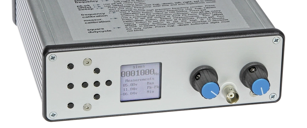
DDS chips are readily available, greatly simplifying the design of the analog part of a wide-range function- or signal generator. All you need to do (they say!) is choose one, add some suitable output circuitry, pick a microcontroller, provide a user interface and start programming. To which we reply: sweet dreams, here is the real story: power to the AD9834!
Original publication: Elektor magazine 5/2015, page 68.
Author: Theodorou Gerasimos (Greece) Post engineering: Ton Giesberts (Elektor Labs)
Free download expires: Friday 17 January 2020.
Specifications
• Direct Digital Synthesis (DDS) with analogue front-end
• Frequency range: 1 – 10 MHz
• Frequency resolution: 0.28 Hz
• Output: 0 – 15 Vpp
• THD+N (100 kΩ load, B > 500 kHz):
— 1 V, 1 kHz: 0.12% (0.09% for B = 22 kHz)
— 5 V, 1 kHz: 0.1% (0.09% for B = 22 kHz)
— 1 V, 10 kHz: 0.1% (0.09% for B = 80 kHz)
— 5 V, 10 kHz: 0.09% (0.08% for B = 80 kHz)
— 1 V, 100 kHz: 0.1%
— 5 V, 100 kHz: 0.08%
• S/N (referred to 1 V): 72 dB
• Maximum output (10 MΩ load):
— Sine: 16 Vpp
— Triangle: 16 Vpp
— Square: 18 Vpp
• DC offset voltage range: –10 to +10 V
• Output impedance: 50 Ω
• Duty cycle (square wave): 1 – 99%
• Rise and fall time (80%, square wave): 100 ns
• Sweep mode
• Power consumption: 3 VA
Like what you’re seeing? Then go to the article page and download a pdf copy of the full, original article. Downloading is free from Friday 10 January to Friday 17 January, 2020.
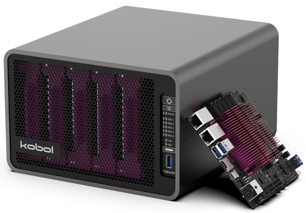
Kobol, the Singapore based manufacturer of Helios4 is set to launch pre-orders for its latest open HW/SW NAS system called the Helios64. The system which was created as an upgrade to the Helios4 NAS system will be available as a Nano-ITX SBC and a complete enclosed system, running the more powerful 64-bit Rockchip RK3399 compared to the Cortex-A9 based Marvell Armada 388 on the Helios4.
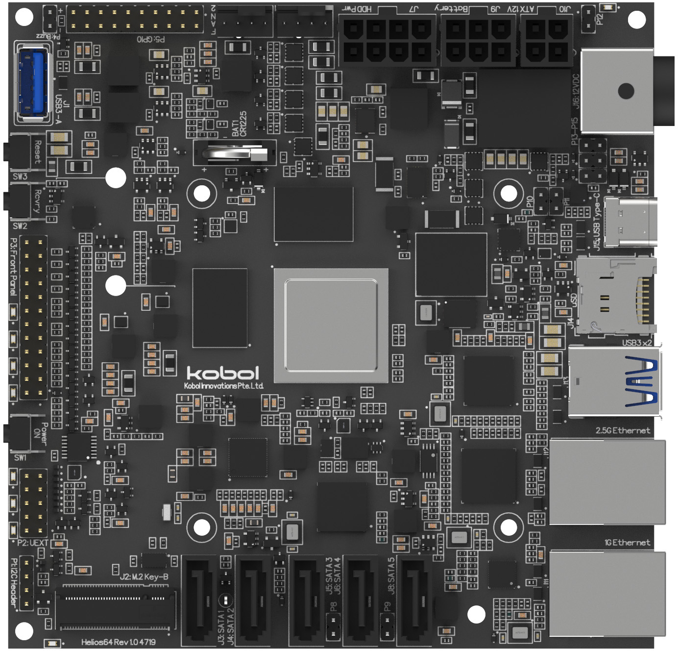
One of the major upgrades to the Helios4 is the use of the RK3399 SOC which comes with 2 x 1.8GHz Cortex-A72 cores, 4 x 1.4GHz Cortex-A53 cores, and a Mali-T860 GPU. To rain in utmost performance levels, the board ships with 4GB LPDDR4 RAM along with a 16GB eMMC 5.1, and a MicroSD slot which could be used to further increase the storage.
Asides the upgrade in the SOC used, the new Helios64 comes with a 2.5Gbs LAN port(1 Ethernet port more than Helios4), a UPS, and an additional SATA interface to bring the total number of SATA III interfaces on it to five(5) (compared to the 4 on Helios4), with the possibility of configuring one of them for use with an SSD via an M.2 slot. In addition to the upgraded interfaces, the board also ships with:
3x USB 3.0 host ports
USB Type-C that supports DP for displays or DAS (Direct Attached Storage) modes.
GPIO and special-purpose I/Os that support I2C, SPI, UART, and 2x PWM fan
Dual DC inputs Power Supply
Built-in UPS with optional battery.
The Nano-ITX SBC comes in a 120×120 size that is slightly larger than the Helios4, while the full five drive systems with enclosure comes in a 250 x 222 x 134mm size with an exposed USB 3.0 port, a control panel and an internal space for dual 80mm PWM fans, and five 3.5-inch HDDs via a hot-plug tray system.
Kobol board
The new Helios64 will go on pre-order next week (Second week in January) with shipping and fulfillment due by March. During the Pre-order stage, the Nano-ITX SBC version will be available for $189 while the enclosure kit versions will go for $285. After the pre-order stage by March 1, the full kit will sell for $295.
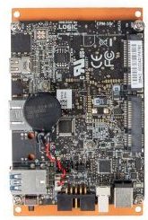
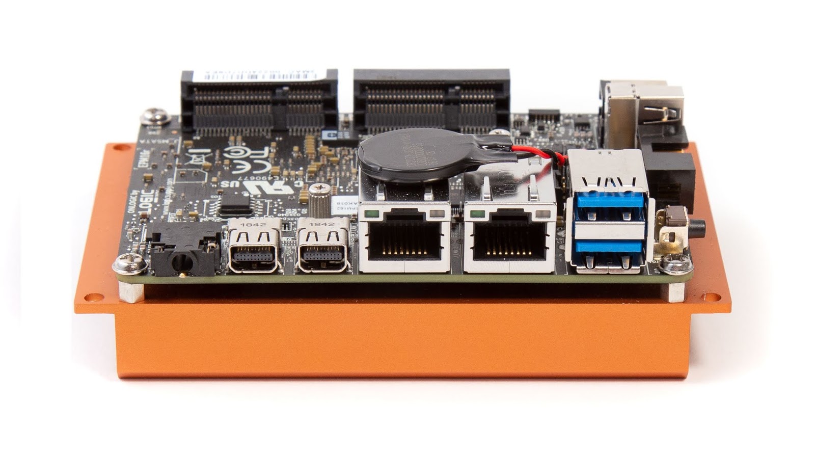
OnLogic (Formerly Logic supply) recently announced the launch of 4 new industrial SBCs based on Intel’s Apollo Lake Pico-ITX processors. The four boards; EPM163, EPM162, EPM161, and EPM160, combine small size (the Pico-ITX 3.9 x 2.8in form factor) with solid performance, with target use cases being diverse industrial applications.
The first board, EPM163, hosts the Quad-Core Intel Apollo Lake N4200 Pentium processor with 4GB of RAM, Intel HD 500 Graphics, and 64 GB onboard storage with support for two mini-PCIe slots (one shared with mSATA). Like all Apollo Lake generation processors, it offers up to a 30% performance boost over systems running on previous architectures and operates with low power consumption and reduced heat production.
For connectivity, the EPM163 features; a 9 pin RS232 box connector COM Port, a USB 2.0 port, two USB 3.0 ports, a MicroSD card slot, two Gb LAN ports, as well as two mini-DisplayPorts capable of 1080p or 4k resolution, with processor support for up to three separate displays at once. The board also features both full-height and half-height mPCIe slots which ensure it can support wifi and 4G connectivity with ease. The board comes with 64 GB of eMMC storage, and up to 1 TB of onboard storage may be added through an mSATA slot (shared with the full-height mPCIe) or using the MicroSD Card slot.
The second board, the EPM162, features the Intel Apollo Lake Celeron N3350 Dual-Core processor with 4GB of RAM, Intel HD 500 graphics, and 32 GB onboard storage for compact and efficient computing with support for two mini-PCIe slots (one shared with mSATA). It features the same type of connectivity/communication ports configuration as the EPM163 and also consumes low power since its processor is also based on the Apollo Lake generation.
The third board, the EPM161, is based on the same Intel Apollo Lake Celeron N3350 processor used in the EPM162, but it features a 2GB RAM(4GB on EPM162) with an 8 GB(32GB on EPM162) onboard eMMC storage. It however also supports up to 1TB of additional storage via the MicroSD Card slot or through an mSATA slot (shared with the full-height mPCIe).
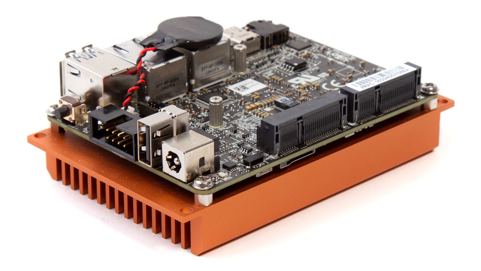
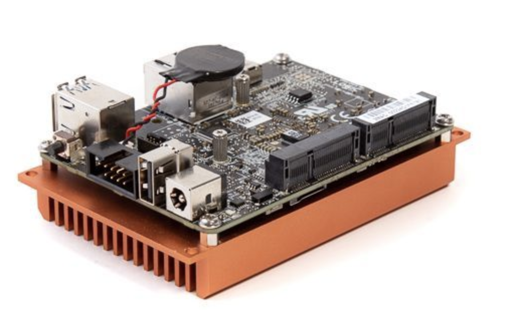
EPM160
The fourth board, the EPM160, features the same dual-core Intel Celeron N335o processor and similar connectivity and performance specs as the EPM161 above with the major difference being a lesser RAM value of just 1 GB.
All four boards can be fully customized by the user to via the Onlogic product page which allows the user to select different options on configurations like Primary Storage size, Warranty years, and preloaded operating system options which include, the Windows 10 IoT Enterprise, and several Ubuntu Desktop and Server OS options.
The boards are already available for sale with the EPM163 starting from $382, the EPM162 starting at $289, the EPM161 starting at $252, and the EPM160 starting at $220.
The increased interest in IoT and electric automobiles around the world is driving an increase in the use of Lithium-Ion/Lithium-Polymer/NiCd/NiMH batteries as more devices and applications are using them, due to their high energy storage capacity to size ratio. This increased interest is, however, causing an increase in the number of batteries with “fake” ampere-hours ratings in the market. These fake ratings could lead to the failure of several projects, especially IoT projects in which developers factor in the Battery ratings in their On-time calculations. As such, to find a way of mitigating the failure-risks this problem poses, for today’s tutorial, we are going to build a battery capacity tester which can be used to get the correct energy storage capacity of any Lithium-Ion/Lithium-Polymer/NiCd/NiMH batteries (with voltage below <5v).
Battery (Lithium, NiMH, NiCd) Capacity Tester Using Arduino – [Link]
The increased interest in IoT and electric automobiles around the world is driving an increase in the use of Lithium-Ion/Lithium-Polymer/NiCd/NiMH batteries as more devices and applications are using them, due to their high energy storage capacity to size ratio. This increased interest is, however, causing an increase in the number of batteries with “fake” ampere-hours ratings in the market. These fake ratings could lead to the failure of several projects, especially IoT projects in which developers factor in the Battery ratings in their On-time calculations. As such, to find a way of mitigating the failure-risks this problem poses, for today’s tutorial, we are going to build a battery capacity tester which can be used to get the correct energy storage capacity of any Lithium-Ion/Lithium-Polymer/NiCd/NiMH batteries (with voltage below <5v).
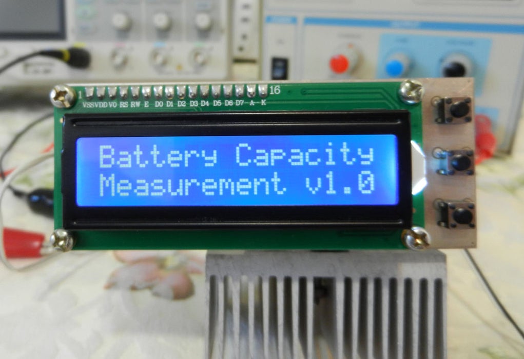
Demo SPlash Screen
There are quite a number of battery testing projects on the internet, each with a different approach, but for today’s tutorial we will be chronicling the efforts of Instructables user: Sam Moshiri, due to the quality of his build and its standalone and compact nature. The goal of the project according to him was to build a compact, easy-to-build device, capable of measuring the capacity of almost any kind of battery (< 5V) using an adjustable constant load setup with an LCD on which the capacity of the battery is displayed.
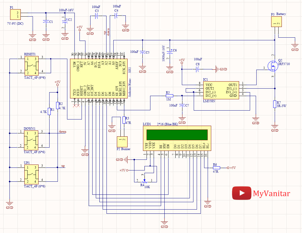
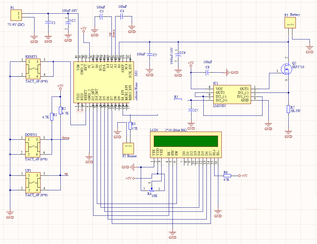
The idea behind the constant load current setup is simple. If you draw a constant current from a battery over a particular period of time, you will be able to calculate the true ampere-hour capacity of the battery based on the amount of voltage that was dropped during that time. To achieve the constant load current, a resistor network with an LM358 operation amplifier and a MOSFET was used. The setup has two push buttons (+ and -) that allow users to set the load current before the process starts, and a third push-button to reset the board when it’s time to test another battery. The Battery’s voltage is fed into one of the analog pins on an Arduino Nano which monitors the voltage drop based on the preset current draw, calculates the battery capacity, and displays it on a 16×2 LCD Display.
At the end of this tutorial, you would know not only how to determine the battery capacity, but also how to design for constant load / constant current draw and use a 16×2 LCD display with the Arduino.
Ready? Let’s dive in!
Required Components
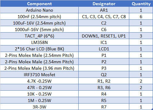
The components required for this project are provided below:
Arduino Nano
16 x 2 LCD Display
LM358N
Resistors – 4.7k(2), 47R(2), 1M, 10k, 3R
Capacitors 100nF(6), 100uf-16V, 1000uF-16V
Tact Switch (3)
IRF3710
Jumper Wires
Battery Holder
Variable Power Supply
Although the project was implemented on a PCB to make it compact, all of the components used are of DIP type to make it easy to solder for everyone, irrespective of the level of their soldering skills. The Arduino Nano was used because it can be easily soldered on a PCB, asides this reason, any other board could have been used.
Schematics
As earlier mentioned, the project was implemented using a PCB to make it portable. The PCB was designed using Altium and all the files are attached under the download section of the tutorial. The components are connected as shown in the schematics below;
A comprehensive BOM showing how each component fits into the schematics above is shown in the table below:
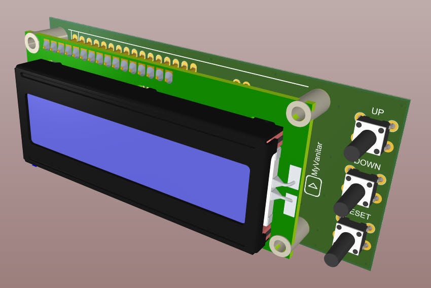
To create the PCB, Sam used the SamacSys component libraries, because of features like the industrial IPC standards which they follow and the fact that they are free. The Libraries were installed using the Altium Library plugin. The PCB after development is shown in the image below along with the assembled version of the board.
assembled PCB
Code
The code for this project is quite straightforward. We will basically monitor the time it takes for a battery to get to a predefined “low” value, and calculate the battery’s capacity using the depletion rate and the preset constant load current that was drawn from it. The whole process is displayed on an LCD in an interactive manner.
To reduce the amount of code to be written, we will use the Arduino Liquid Crystal library along with the JCbutton library. The liquid crystal library which comes preinstalled on the Arduino will be used to interact with the 16×2 LCD, while the JCbutton library, which can be downloaded from the attached link, is used in processing the state of the tact buttons, determining when it has been pressed, long pressed, etc., while also handling things like debounce.
As usual, I will do a quick explanation of how the code works with a focus on sections that I feel might be difficult to follow.
The code starts by importing the two libraries that will be used.
#include <LiquidCrystal.h>
#include <JC_Button.h>
Next, we create a variable to hold the minimum level to which the battery is allowed to drop, and several other variables to store different values. The Current array is a series of value which is matched to the rotation of the R7 potentiometer which determines the load current.
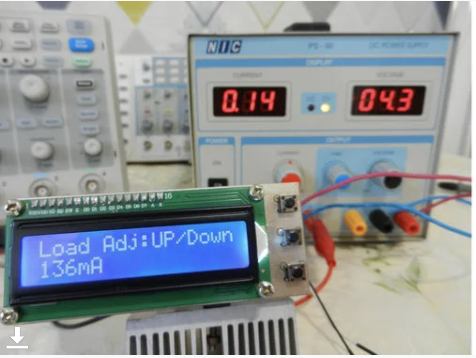
After initializing the LCD, display a splash screen of some sort with the name of the project and the version. After 3s, the display is cleared and it displays the Load Adj: up/Down button showing it is waiting for the user to set a load current.
Each time the Up button is pressed, it adds 5 to the Pwm_Value variable which is used as the load current indicator. The inverse is true for the Down button. For each of the button pressed, the user is provided with visual feedback of the increase or decrease in the PWM_value, on the Display.
If the Up button is long pressed (indicated by 1000ms), the system switches mode as it assumes the user has selected a load current that satisfies them. The mode switch involves invoking the timer interrupt() function which handles all the calculations involved with determining the capacity of the battery. This cycle is repeated as the loop continues.
The timerInterrupt() function handles most of the project’s heavy lifting. It continuously monitors the battery voltage and as long as it’s not yet at the preset Low_BAT_Level, it increments the time. As soon as the measured battery voltage becomes less than the Low_BAT_Level, it stops the time increment and uses it to estimate the capacity of the battery. At this point, the buzzer is turned on and off in a pattern to indicate the completion of the process.
With the code completed and your PCB ready, connect the Arduino Nano to your computer and upload the code to it. After the code upload, you should see the LCD come up with the splash screen as shown in the image below.
Demo Splash Screen
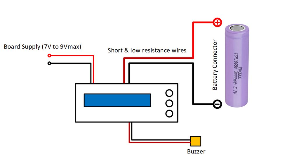
With the code uploaded, we then need to power the board via an external power supply and connect a battery to it as shown in the image below. Based on this current design, you should only power the board with a maximum of 9V.
With the power supply and battery connected, set your desired load Current using the up and down buttons then press and hold the up button till you hear the buzzer beeps, to kick start the process.
Set the desired Load Current
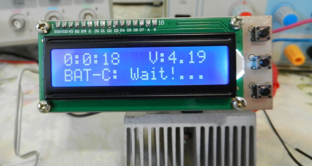
As the process proceeds, an update will be provided on the screen, showing the time that has elapsed and the voltage of the battery.
Capacity Determination in Progress
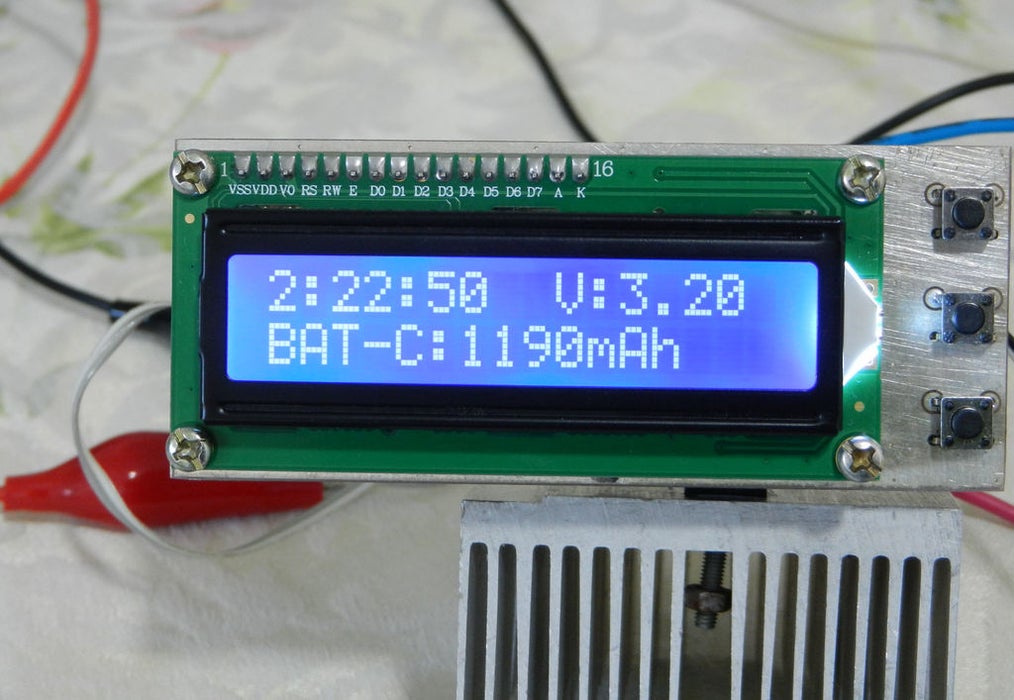
At the end of the process, the battery’s true capacity is displayed as shown in the image below.
Battery Capacity.
That’s it. For the demo, a battery rated 8800mAh was used but at the end of the test, the battery was discovered to only have an energy capacity of 1190mAh.
That’s it for this tutorial guy’s thanks for reading. As usual, you can reach out to me via the comment section if you have any questions or difficulties replicating the project.
Within a period of 10 years at the end of the 19th century, many technological achievements allowed to extend the use of alternating current and overcome the limitations of direct current for the distribution of electricity to the public.
In 1882, the transformer is invented in France which eases the distribution of the alternating current as we will mention in the first section. Only six years later, Tesla created the first prototype of the synchronous machine which as we detail in the main core of this tutorial, generates a particular form of alternating current from a primary form of energy.
This particular alternating current can be described by a mathematical function and is commonly known as a sine or sinusoidal waveform. In this tutorial, we will refer to several previous articles to regroup information and give more details about the sinusoidal waveform.
First of all, a short presentation will define the important parameters of a sine function and why it is so important in electronics.
In a second section, we investigate their generation process with alternators which includes an understanding of electromagnetic phenomena. We focus on the architecture of the rotor and stator which are the two most important parts involved in electricity generation.
Presentation
Sine waveforms are found in many domains of maths and physics and they can be mechanical or electrical for example. They describe a periodic and smooth oscillation of a certain parameter (current, voltage, movement …etc).
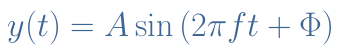
The electrical sine waveform is described mathematically by the sine function y(t) and the general formula is given below :
eq 1 : Sine function expression
The parameter A is the amplitude which unit is in Amps (A) or Volts (V), f is the frequency of oscillation in Hertz (Hz) or the angular velocity ω in radians/second (rad/s) and Φ is the instant phase of the signal in degrees (°) or radians (rad). The oscillation speed can also be given by the period T=1/f which represents the time duration of a cycle.
We also remind the reader that Equation 1 can be transformed into its complex equivalent for simplification and compaction purposes, such as detailed in the tutorial about Complex Numbers.
The conversion between radians to degrees can easily be done knowing that 2π rad=360°. Moreover, the frequency and angular velocity are linked by the identity ω=2πf.
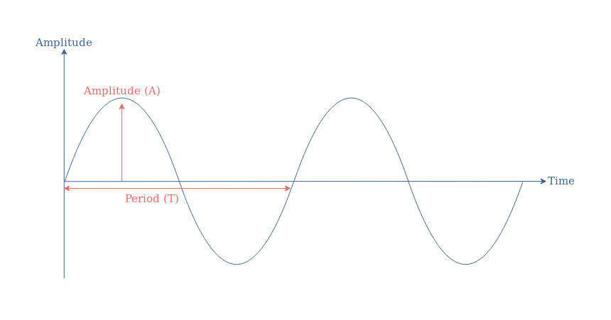
An illustration of these parameters is given in Figure1 that compares two different sine functions.
fig 1 : Illustration of sine functions
In order to know if the phase is different from zero, we can look at the variation of the sine around the origin of time. A sine wave with no instant phase should have an amplitude of 0 at t=0 and increase right after, which is the case of the blue sine function y2(t).
Before talking about the production of such signals, it is worth mentioning why they are so interesting and why they are used in so many applications.
First of all, as we will see in the next section, sine signals can be naturally produced with generators in power plants. Moreover, as already detailed in the AC Waveform tutorial, they are the building blocks of any other period signals such as squares, ramps … Finally, the entire distribution network is based on the use of sine power waveform because their current and voltage amplitudes can easily be adjusted to specific needs with the help of transformers, the transmission power losses are as well decreased.
Generation
The reader is encouraged to refer to our previous articles about AC Waveform and AC Inductance in order to get a preview of what this section will detail in the following.
The generation of an electrical sine signal is done by a synchronous electric motor also known as alternator. The goal of such a device is to transform mechanical energy (rotation) into electricity.
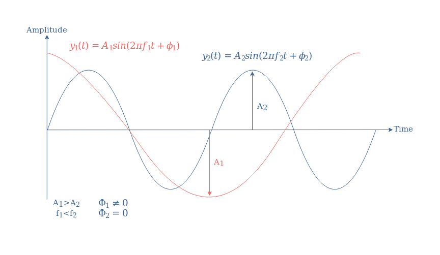
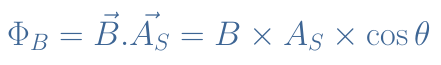
The following Figure 2 presents the schematic architecture and the functioning of a single pole-pair alternator :
fig 2 : Illustration of the functioning of an alternator
The alternator consists of two parts : a stator and a rotor. As the name refers to, the stator is a stationary coil in which the AC electricity is induced and harvested. The rotor is a rotational magnet that generates a magnetic field inside the stator.
The rotation of the rotor is maintained by a primary form of energy : combustion of coal or nuclear material, wind, movement of water in a dam etc … It can be a permanent magnet in which the magnetic field is constant or an electromagnet in which the magnetic field can be tuned depending on the electricity supplied to it. Often, the second option is chosen because a variable amplitude of the magnetic field allow to change the amplitude of the output electrical signal.
The stator is where the induced electric signal is generated thanks to the induction phenomenon. The electric signal produced is naturally a sine waveform because of the circular symmetry of the configuration.
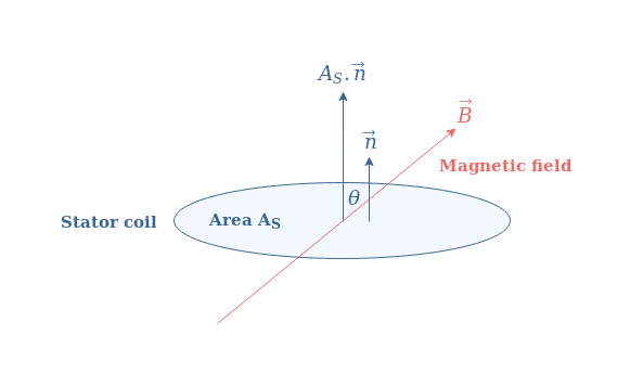
Indeed, according to the induction law, the electric signal e (either the current or voltage) is proportional to the variation of the magnetic flux ΦB within the stator: e=-dΦB /dt. If AS states for the area of the stator coil, we can define a surface vector given by AS=AS.n with n being the unit normal vector to the same surface as shown in Figure 3 :
fig 3 : Illustration of the surface vector of the stator coil and magnetic field
The magnetic flux is simply given by a vectorial product of the field B and the area vector of the stator coil AS :
eq 2 : Expression of the magnetic flux
If we set the angle θ to be at 0° when the axis of the rotor and stator are aligned, we can understand that ΦB=Φmax×cosθ with Φmax=B×AS, the variations of the flux is, therefore, also a sine waveform since the derivative of a cosine is a sine and the angle θ is a function of time. Finally, we can say that the electric output will be as well a sine waveform.
Rotor pole-pairs
An important relation between the frequency of the electric sine output (f) can be given and the rotation speed of the rotor (in RPM) : RPM=60×f. In order to obtain a 50 Hz signal, which is the distribution norm in Europe, the rotor must rotate at 3000 RPM. This high speed can be achieved in a nuclear power plant but in dams, for example, the rotation is much slower.
To maintain a frequency of 50 Hz, a solution consists of increasing the number of pairs of poles of the rotor such as illustrated in Figure 4. With this configuration, a faster variation of the magnetic flux is achieved for the same rotation speed.
fig 4 : Illustration of a double pole-pair alternator
For this example, a 50 Hz output can be observed with a rotation speed of 1500 RPM instead of 3000 RPM. In the general case, if P states the number of pole-pairs, the relation between the rotation speed and output frequency is given by the Equation 3 :
eq 3 : Expression of the rotation speed as a function of frequency and rotor pole-pairs
Stator pole-pairs
In the previous illustrations, the stator consists of only 1 pair of the pole which gives a single-phase current. For high-power applications, however, such as high-voltage distribution, a 3-phase current is more suited since it presents fewer power losses and a more constant average power.
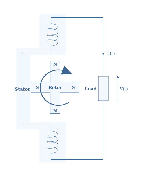
The architecture of such a stator is presented in the Figure 5 below :
fig 5 : Illustration of a 3 pair-pole stator with a single pair-pole rotor
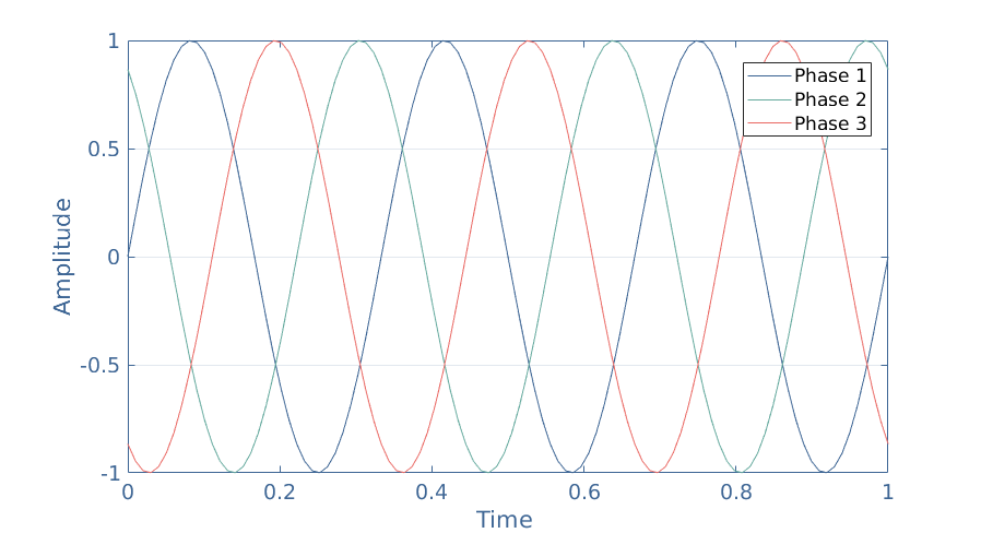
Each phase is separated 120° from the rotation center of the rotor and one pole of each phase in grounded. The total output is, therefore, a combination of 3 sine waves phase-shifted 120° such as presented in the Figure 6 :
fig 6 : Total output of a 3-phase alternator
Most of the modern alternators consist of a 3 pole-pair stator which allows the production of 3-phase sine waves and provides better efficiency. Moreover, a multi pair-pole rotor can be combined in this configuration in order to obtain the required frequency even if the mechanical rotation is slower than 3000 RPM.
Conclusion
Sine waveform plays a major role in many physics domains and especially in electronics since they are present in our daily life, supplying households for more than a century, worldwide.
In the first section of this tutorial, we mathematically described what a sine wave consists thanks to the sine function and explained the amplitude, frequency and phase parameters. We also briefly explain the importance of such signals.
The main core of this article refers to the production of sine signals through the use of alternators. They consist of a rotational part (the rotor) that creates a variable magnetic field in a static coil (the stator) surrounding it. According to the electromagnetic law of induction, an electric sine wave is produced in the stator.
We have pinpointed that the number of pole-pairs of both the stator and rotor can be modified in order to maintain a 50 Hz output with a slower rotation of the rotor or to achieve a 3-phase signal for high-power applications.
Strange Parts visiting a giant factory in China that makes lipo iPhone batteries, aka lithium polymer batteries, and seeing how they are made from start to finish. This is by FAR the coolest and biggest factory I’ve been to date.
Inside an iPhone Battery Factory – in China – [Link]
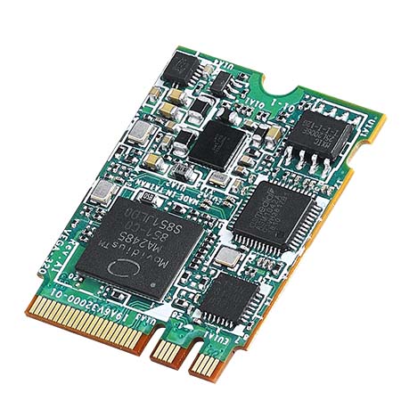
Advantech VEGA-320 m.2 Edge AI Module is an ultra-compact and low power consumption module with one onboard Intel® Movidius™ Myriad™ X VPU. This module is scalable for multiple video streams edge inference. The VEGA-320 module includes a built-in Edge AI suite. This Edge AI suite features OpenVINO™ toolkit, pre-trained modules, deployment wizard, and third party AI SDK. The VEGA-320 module supports Windows 10 Enterprise, Ubuntu 16.04.3 LTS, and CentOS 7.4. This module operates at 0°C to 45°C temperature range. The VEGA-320 also features passive cooling and hardware acceleration for common deep neural networks. This module is ideal for use in facial detection, pedestrian tracking, human pose estimation, vehicle detection, and optical inspection.
Features
Built-in Edge AI Suite:
OpenVINO™ toolkit
Pre-trained models
Deployment wizard
3rd party AI SDK
TensorFlow and Caffe framework support
Intel® Movidius™ Myriad™ X VPU onboard
Ultra-compact and low power consumption
Hardware acceleration for common deep neural networks
Scalable for multiple video streams edge inference
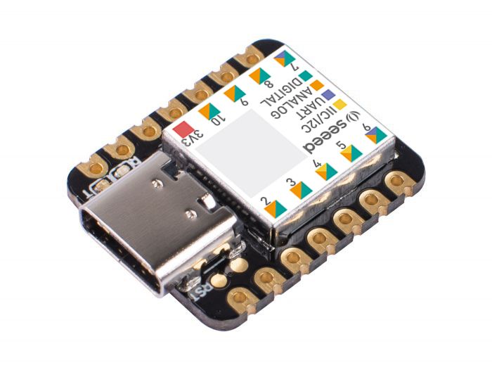
Take a look at Seeeduino XIAO. What a small size and cute looking! It is the smallest member of the Seeeduino family. Seeeduino XIAO still carries the powerful CPU-ARM® Cortex®-M0+(SAMD21G18) which is a low-power Arduino microcontroller. On the other hand, this little board has good performance in processing but needs less power. As a matter of fact, it is designed in a tiny size and can be used for Arduino wearable devices and small projects.
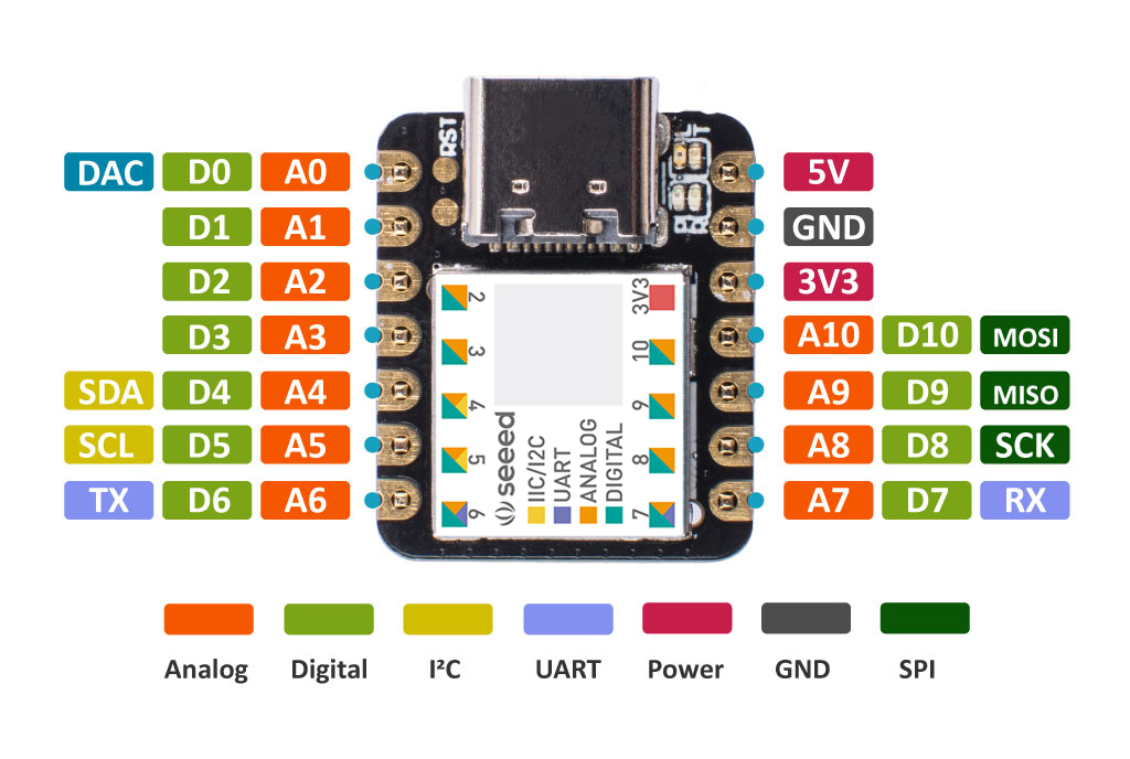
Apart from the strong CPU, Seeeduino XIAO is excellent in many other functions. It has 14 GPIO PINs, which can be used for 11 analog PINs, 11 digital PINs, 1 I2C interface, 1 UART interface, and 1 SPI interface. Some PINs have various functions, A1/D1 to A10/D10 Pins have PWM functions and Pin A0/D0 has a function of DAC which means you can get true analog signals not PWM signals when you define it as an analog pin, that’s why 14 GPIO PINs can realize more I/O PINs and interfaces. Moreover, Seeeduino XIAO supports the USB Type-C interface which can supply power and download code. There are power pads at the back of the XIAO which support battery and make it designed for wearable devices to become realistic. Except for the power LED, we add a user LED on board for your better coding experience. Usually a Dev. Board as small as this size will use the chip’s inner crystal oscillator for time fixing, in order to make the clock more accurate, Seeeduino XIAO layouts an extra 32.768KHz to make the clock more stable.
Seeeduino XIAO is perfectly compatible with Arduino IDE, you can easily develop some small projects with the help of the large and comprehensive Arduino library. So get one and you will soon love it!