STMicroelectronics TCPP01-M12 USB Type-C Port Protection

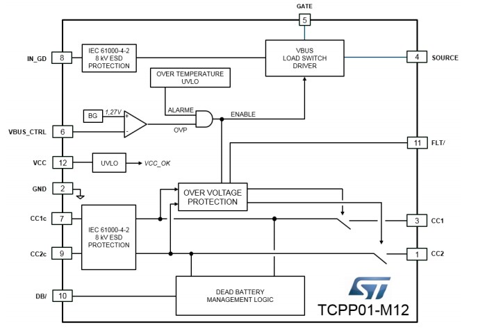
STMicroelectronics TCPP01-M12 USB Type-C Port Protection is a single-chip solution that facilitates the migration from USB legacy connectors type-A or type-B to USB Type-C connectors. This Type-C port protection features overvoltage protection on VBUS, adjustable up to 22 V, with external N-channel MOSFET. The TCPP01-M12 USB port protection includes an integrated charge pump to control the gate of an external N-channel MOSFET. This Type-C port protection offers Over Temperature Protection (OTP), open-drain fault reporting, and integrated dead battery.

The TCPP01-M12 USB port protection operates at -40°C to 85°C junction temperature range. This Type-C port protection function with 6V overvoltage protection, 150°C junction-to-ambient thermal resistance, and 122μA supply current. The TCPP01-M12 USB Type-C port protection is ideal for use in sink configuration, source configuration, UFP or DFP configuratioN, power delivery, and PPS compliant.

Features

  • Overvoltage protection on VBUS with external N-channel MOSFET
  • System-level ESD protection for USB type-C connector pins
  • Compliant with IEC 61000-4-2 level 4
  • Integrated charge pump to control the gate of an external N-channel MOSFET
  • Null quiescent current when no USB charging cable is attached for battery operated “consumer/sink” applications
  • Integrated “dead battery” (RD resistors)
  • Over-temperature protection
  • Complies with the latest USB Type-C and USB power delivery standards
  • Compliant with Programmable Power Supply (PPS) as defined in the latest USB PD specification
  • Open-drain fault reporting
  • ECOPACK2 compliant

Specifications

  • 6V overvoltage protection
  • At Absolute maximum ratings (Tamb = 25°C):
    • -40°C to 85°C operating junction temperature range
    • -55°C to 150°C storage temperature range
    • 150°C/W junction-to-ambient thermal resistance
  • At Power supply and leakage current, Tamb = -40 °C to 85 °C:
    • 3V to 3.6V input voltage range
    • 120μA supply current

Applications

  • USB Type-C for UFP (upstream facing port) or DFP (downstream facing port) configuration
  • USB Type-C power delivery, PPS compliant
  • USB Type-C used in sink configuration (consumer)
  • USB Type-C used in source configuration (provider)
TCPP01-M12 USB Type-C Block Diagram
more information: www.st.com

iWave Systems Introduces a SOM based on ZU19EG / ZU17EG / ZU11EG Xilinx ZynQ UltraScale+ MPSOC

iWave Systems introduces a powerful SOM (System on Module) with six heterogeneous ARM processor cores (four 64-bit ARM Cortex-A53 and two 32-bit ARM Cortex-R5 Cores), an ARM Mali-400 MP2 GPU, and a big chunk of the latest-generation UltraScale+ programmable logic cells scaling all the way to 1 million. Designed a ZU19EG / ZU17EG / ZU11EG Zynq UltraScale+ MPSoC System on Module in the package C1760 and a 10+ Years Longevity support.

The CPU module has a compact-size measuring 110mm by 75mm, equipped with ZU19/17/11 EG MPSoC, 64-Bit 4GB DDR4 for PS, dual 4GB DDR4 64-Bit for PL, 8GB eMMC (expandable up to 128GB) as well as integrated with Ethernet PHY, USB PHY, and power circuitry to provide control and processing capabilities as an embedded system. Besides these, all the FPGA IOs, 16 x PL-GTY @32.75Gbps, 32 x PL-GTH @16.3Gbps, 4 x PS-GTR @6Gbps Transceivers & FPGA IOs up to 48LVDS/96SE + 46SE IOs are terminated at high-speed Board-to-Board (B2B) connector.

Product Highlights:

It is ready to run Linux OS and targets a wide variety of applications like the High-Speed Networking using 25G, 40G & 100G Optical, Cloud Computing, 4K Video Surveillance System, Deep Neural AI/ML Networks, Automotive Imaging Radar, Intelligent Data Center, etc.,

Targeted Applications

iWave Systems has the stock of various ZU19EG / ZU17EG / ZU11EG MPSoC based SOMs which is ready for immediate dispatch

iWave Systems also offers a versatile iW-RainboW-G35D Development Board for evaluating the SOM Module. It takes full features of the Zynq UltraScale+ MPSoC device to have explored a robust set of peripherals such as Dual FMC for doing initial POC with the available off-the-shelf FMC boards, 12G SDI IN & OUT, SFP+, USB 3.0 Type C, Gigabit Ethernet, Dual PMOD, DisplayPort (DP), PCIe x4 interface, M.2 SATA interface, JTAG, CAN and so on. The iW-RainboW-G35D is a solid reference design for development based on Xilinx Zynq UltraScale+ MPSoC solutions.

More information about the new products can be found at:

For further information or enquiries please write to mktg@iwavesystems.com or contact our Regional Partners.

SEGGER’s SystemView adds data acquisition via UART and TCP/IP

SEGGER announces the release of SystemView V3.10, a major update to its system verification tool for embedded systems. The most significant enhancement is the addition of real-time data acquisition via UART or TCP/IP. Any system with UART or TCP/IP connection, typically Ethernet, can now be monitored and verified.

The new version comes with the target code required for integration as well as example projects.

The software also adds a variety of new features. New performance markers are useful for performance verification and optimization. A new Runtime window provides information on the runtime distribution of tasks, interrupts and software timers. All windows are updated in real-time, with no limit on the sampling time due to streaming data acquisition. The entire data set can be stored for later or remote analysis as well as archival and documentation purposes. SystemView also comes with the files required for many popular RTOS such as embOS, FreeRTOS, uC/OS-II and uC/OS-III, and more. Any system, with or without RTOS, can be monitored.

SystemView V3.10 can be easily downloaded and installed without any registration process. It is available under SEGGER’s friendly licensing policy, and –like SEGGER’s Ozone debugger and SEGGER’s Embedded Studio IDE – is free for non-commercial purposes as well as unlimited evaluation, even for the commercial user. Previous releases of the software continue to be available on segger.com.

SystemView, like Ozone and Embedded Studio, works cross-platform for Windows, macOS, and Linux.

For more info on SystemView see https://www.segger.com/products/development-tools/systemview/

High speed switching N-channel MOSFET for general purpose

Torex Semiconductor has launched its new XP231N0201TR (30V withstand voltage) for MOSFETs. The product is a general-purpose N-channel MOSFET with low on resistance and high speed switching. It can be used for various applications such as relay circuits and switching circuits. The gate protection diode is built-in as a static protection.

Furthermore, the XP231N0201TR is in a compact SOT-23(TO-236) (2.9×2.4×1.15mm height) package with contributing space saving.

Features

These environmentally-friendly products comply with the EU RoHS Directive and are lead-free.

more information: www.torexsemi.com

Pod Bay 3’s PiRyte Brings ATX Power and Active Cooling to the Raspberry Pi Family

Overheating and the resulting drop in performance and throughput has been one of the major drawbacks associated with using the Raspberry Pi. Several solutions have been developed to provide active or passive cooling solutions for it. One of the most recent solutions is the third generation of the PiRyte developed by Pod Bay 3.

The PiRyte is a Raspberry Pi add-on that provides ATX-style desktop PC power supply to be used as a power source for the Pi and a mounting space for a 40mm fan (to be provided by the user) which can be used for active cooling of the Pi. Describing the product on its Tindie page, Tom Tibbetts of Pod Bay 3 said,

“This third-generation Desktop/Server ATX Power Supply Expansion Module and Soft Switch allows you to power your Raspberry Pi and add-on project boards using inexpensive desktop power supplies while keeping your Raspberry Pi cool with an off the shelf fan that you provide”.

Some of the features of the HAT as listed on the Project’s Tindie page include;

  • Uses inexpensive off the shelf ATX desktop supply. Works with 24 pin ATX connectors.
  • Enables the operating system to perform a controlled shutdown and reboots to minimize disk file corruption.
  • You can program the Mini ATX PSU-Cool so that it will automatically reboot after a power failure if it was previously turned on.
  • Back powers the Raspberry Pi with a dedicated 5 VDC line.
  • Compatible with common 40mm X 40mm fans with 4.2mm diameter mounting holes on 32mm centers.
  • PCB is 1oz copper with ENIG finish.
  • Uses high-quality Samtec and Molex connectors.
  • Conforms to the Raspberry Pi Foundation’s HAT footprint.
  • 40 Pin GPIO stacking header allows the use of other HAT conforming boards.
  • I2C signals brought out so you can plug in external modules such as a real-time clock
  • It comes as a DIY kit to keep costs low. Assembly required
The HAT Comes as a Kit

The new PiRyte which could be connected directly to the RPI GPIO or used in a stacking system to enable the use of other HATs runs a firmware, similar to that of the previous generations, that helps prevent the corruption of valuable files which could occur as a result of indiscriminate power cut to the Pi, by enabling a controlled shutdown of the Pi’s Operating System. This is however done in a coordinated version such that, the controller is able to recognize and act appropriately when the Pi is deliberately turned off by the user(command line) or by an application. A summary of some of the operating modes of the HAT, as listed on the tindie’s page include;

  • Program Mode: By default, the Mini ATX PSU-Cool is programmed to not auto-reboot after a power failure if it was already turned on. This is to maintain backward compatibility with older model units. If you wish to have the Mini ATX PSU-Cool automatically reboot after power is restored, then please refer to the programming instructions in the manual.
  • Power Off: On-board microcontroller, powered by the desktop 5Vsb line, waits for momentary power on button to be pressed.
  • Power Up: LED pulsates slowly. Power is supplied to the Raspberry Pi and it boots up.
  • Reboot: LED pulsates slowly. Raspberry Pi shuts down then reboots.
  • Shutdown: LED pulsates slowly until bootup script has ended then pulsates quickly for 10 seconds before shutting off power to the Pi
  • Hard Shutdown: LED dims the entire time push button is depressed. Turns off the power after 10 seconds.
Allows a 40mmx40mm fan for cooling

To enable the use of the device for cooling, it comes with a circular 40mmx40mm cut-out on top of which users can install a fan for active cooling which will definitely be required if you are running the Raspberry Pi in an overclocked mode or performing sustained, heavy CPU intensive tasks.

The ATX power supply used showcases an immense amount of thoughtfulness from Pod Bay as it makes it immensely useful for projects in which users need more than the popular 3.3v/5v voltage supply.

The PiRyte has a lot of competition in the Raspberry Pi HAT market for both power and heat management, but not as much competition for both features combined. This will definitely give the product an edge with users.

The product is currently available as a kit and it goes for $32.95 (excluding shipping) on Tindie. More information on the project and accompanying discounts can be found on its Tindie Project Page.

Keithley SMUs emulate classic curve tracers with new software

Tektronix brings many of the key features loved in classic curve tracers to Keithley SourceMeter source measure units (SMUs) with the release of its Keithley I-V Tracer software. Tektronix introduced the industry’s first curve tracer in 1955 to display characteristic curves for vacuum tubes. This was followed by models for testing transistors, diodes, and other solid-state devices. Production of the curve tracers stopped in the mid-1980s.

Approximating a power supply and an oscilloscope packaged in the same box, curve tracers source voltage while plotting voltage versus current, said Joseph Gorley, product manager at Keithley. Because an SMU can source voltage or current while measuring voltage and current, it has similar hardware qualities to a curve tracer, he added.

The new software leverages the touchscreen interface of 2400 Series graphical SMUs to recreate the familiar user experience of a curve tracer for low-power two-terminal devices. The Keithley I-V Tracer uses the full capabilities of supported SMUs, including the dual high-speed digitizers of the Keithley 2461, to perform tracing with AC polarity and pulsed DC, in addition to standard DC polarity.

Fig. 1: Keithley I-V Tracer software leverages the touchscreen interface of 2400 Series graphical SMUs to recreate the familiar user experience of a curve tracer for low-power two-terminal devices.

The Keithly I-V Tracer is priced at $1,499 plus the cost of the SMU. See the software in action here.

read more

Running Cryptography on a Raspberry Pi Zero on the Space Station

The Raspberry Pi over time has wowed us with its versatility showcased in diverse intriguing applications in which it is used. It is served as the onboard computer powering diverse industrial equipment while also providing the edge needed in some medical experiments. However, it recently (literally) raised the bar for its possible use cases, when the Pi Zero variant was deployed to serve as the brain for a Cryptographic Experiment currently running on the International Space Station (ISS).

Apparently, security is a threat, not just to devices on the earth’s surface, but also to devices outside of the earth’s surface, in Space. Until recently, a large percentage of satellite signals and data communications have been without encryption, but as CyberSecurity threats increase, and the services delivered by satellites of all types, becomes an integral part of our everyday life, it is becoming very important to ensure Security on all levels, to reduce the vulnerability of the satellites to hacking. This had been the focus for several Space stakeholders meetings, and in April 2019, at an attempt solving some of the issues associated with encrypting satellite signals were launched.

The experiment called the Cryptographic Ice Cube Experiment or CrypticIC for short was developed to solve the problems of radiation when sending encrypted communications in space. It was designed to examine how encryption keys can be scrambled when radiation hits the memory and processors doing the encryption in orbit. According to EAS software product assurance engineer Emmanuel Lesser,

“Our CryptIC experiment is testing technological solutions to make encryption-based secure communication feasible for even the smallest of space missions. This is commonplace on Earth, using, for example, symmetric encryption where both sides of the communication link share the same encryption key, however, In orbit the problem has been that space radiation effects can compromise the key within computer memory causing ‘bit-flips’. This disrupts the communication, as the key on the ground and the one in space no longer match. Up to now, this had been a problem that requires dedicated – and expensive – rad-hardened devices to overcome.”

According to Emmanuel, the solution was based on a regular, off-the-shelf, Raspberry pi Zero which was covered with a plastic “Conformal” coating to fulfill fire standard requirements by the International Space Station. The choice of the Raspberry Pi Zero according to him was based on the desire to have a small footprint, relatively modest energy consumption, and secure communication using the cheapest components available.

CrypticIC installed on the International Space Station

The Pi Zero runs the Space-hardened version of Raspbian which had been previously commissioned by ESA. With the success of the project, and the desire of Emmanuel and the team to stick to the Raspberry Pi Zero in the future (although a version with no WiFi and more RAM), it is safe to say we should expect to see more Raspberry Pi based Space applications.

More information on the Cryptographic ICE Cube experiment can be found on the project page on ESA’s Website. 

EconoDUAL™ 3 with TRENCHSTOP™ IGBT7 for an unmatched 900 A power rating

Infineon Technologies AG introduced the new IGBT7 chip for its well-known Easy housing platform in March. Now it is taking the state-of-the-art TRENCHSTOP™ IGBT7 to the arena of medium power: in the standard industry package EconoDUAL™ 3. In this chip technology, the 1200 V module provides a leading nominal current of 900 A enabling a 30 percent higher inverter output current for the same frame size compared with the former technology. While specific improvements of the module’s chip and housing directly aim at industrial drive applications, it can also be very well implemented in designs for commercial, construction and agricultural vehicles (CAV), servo drives, as well as solar and UPS inverters.

Based on the new micro-pattern trench technology, the TRENCHSTOP IGBT7 chip performs with much lower static losses compared to the IGBT4. Its on-state voltage is reduced by up to 30 percent for the same chip area. This brings significant loss reduction in the application, especially for industrial drives, which usually operate at moderate switching frequencies. Additionally, the oscillation behavior and the controllability of the IGBT have been improved. The power modules feature a maximum allowed overload junction temperature of 175°C.

Another improvement concerns the freewheeling diode (FWD) which has also been optimized for drive applications. The forward voltage drop of the emitter-controlled 7 th generation diode (EC7) is now 100 mV lower than the forward voltage drop of the EC4 diode, with reduced oscillation tendency during diode turn-off.

The higher power density of the EconoDUAL 3 helps to avoid paralleling of modules, which leads to a simplification of the inverter design and lower costs. Moreover, the new technology can be implemented in the same footprint facilitating the upgrade of existing inverter system designs. The EconoDUAL 3 module comes with improved housing for handling higher currents and temperatures. It is available with pre-applied thermal interface material (TIM) for the lowest thermal resistance and longest lifetime. The PressFIT housing enables a fast and cost-efficient assembly.

more information: www.infineon.com

Three-channel power supplies deliver up to 375W

Programmable, low-noise, three-channel power supplies that deliver up to 375W in a compact 2U high, half-rack-wide enclosure have been introduced by Tektronix. The Keithley Series 2230G is designed for maximum flexibility, accuracy, and low noise when testing high power, multi-voltage circuits such as LED drivers, automotive, and power-IC circuits.

The power supplies’ three channels are isolated, independent and individually programmable with remote sensing for each channel.

“Designers and test engineers are being challenged to test high-power circuits with a wide range of voltage levels and current draws in compact test environments, while also ensuring minimum noise and maximum accuracy,” said Lori Kieklak, vice president and general manager, Keithley Product Line at Tektronix. “This is particularly the case in R&D and in stacked, tightly spaced automated setups with high production throughput. Keithley’s new series of multichannel power supplies provide the best performance and flexibility needed for testing a wide range of product configurations.”

To provide this flexibility, the 2230G-30-3 provides 195W with two 30V, 3A channels and a 5V, 3A channel, while the 2230G-30-6 and 2230G-60-3 provide up to 375W, with two 30V, 6A channels and two 60V, 3A channels, respectively.

Both 375W versions also have a 5V, 3A third channel. For higher voltages or currents, 30V channels can be combined in series to get up to 60V, and two or three channels can be connected in parallel to deliver up to 15A from the 2230G-30-6. All channels are simultaneously displayed on the front-panel display.

To minimize the effects of noise on the device under test (DUT), the triple output power supplies use a linear design with <1mV RMS ripple and noise.

Features:

  • 195 W model has two 30 V, 3 A channels and one 5 V, 3 A channel
  • All channels are independently controlled and are isolated to power a wide range of test setups
  • All channels have remote sensing so the programmed voltage is accurately applied to the load
  • Set and monitor output voltages with 0.03% basic accuracy and 1 mV resolution
  • Monitor load current with 0.1% basic accuracy and 1 mA resolution
  • Low noise, linear regulation with <1 mV rms ripple and noise
  • Voltage and current outputs of three channels are displayed simultaneously for immediate observation of each output state
  • USB, GPIB, and RS-232 interfaces and rear panel connections for automated test convenience

The linear design also ensures the supplies don’t add to ambient noise and affect other sensitive instrumentation being used for the test.

Using the supplies’ remote sensing capability, the user can set and monitor output voltages with a 0.03% basic accuracy and a resolution of 1mV. Load current can be monitored to 0.1% basic accuracy, and 1mA resolution.

The programmable multiple output power supplies include both front and rear access to the power outputs for orientation flexibility in test setups while minimizing required lead lengths to reduce noise pickup, minimize losses, and keep the test setup neat.

The 2230G Series comes with three standard interface options for PC-based control:  USB, GPIB, and RS-232.

The 2230G Series are available for purchase for €1,230 – €1,500. More information: www.tek.com

MAX20075 Mini Buck Converter

Maxim’s MAX20075 mini buck converter helping improve automotive ECU design with a low-Iq buck converter.

The MAX20075/MAX20076/MAX25276 are small, synchronous buck converters with integrated high-side and low-side switches. The MAX20076/MAX25276 are designed to deliver up to 1.2A and the MAX20075 up to 0.6A, with 3.5V to 36V input voltages. The devices provide an accurate output voltage of ±2% within the normal operation input range of 6V to 18V. With 20ns minimum on-time capability, the converter is capable of large input-to-output conversion ratios. Voltage quality can be monitored by observing the PGOOD signal. The devices can operate in dropout by running at 99% duty cycle, making them ideal for automotive and industrial applications. The devices offer two fixed output voltages of 5V and 3.3V. In addition, the devices can be configured for 1V to 10V output voltages using an external resistor-divider. Frequency is internally fixed at 2.1MHz, which allows for small external components and reduced output ripple, and guarantees no AM interference. The devices offer pin-enabled spread-spectrum-frequency modulation designed to minimize EMI-radiated emissions due to the modulation frequency.

The MAX20075/MAX20076 /MAX25276 are available in small (3mm × 3mm) 12-pin TDFN and side-wettable TDFN packages with an exposed pad, and use very few external components.

Key Features

  • Synchronous DC-DC Converter with Integrated FETs
    • MAX20075 = 0.6A IOUT
    • MAX20076/MAX25276 = 1.2A IOUT
    • For applications requiring low quiescent current/ skip mode operation, please refer to MAX20075D/ MAX20076D/MAX25276D. This device is only recommended for FPWM operation
  • 20ns Minimum On-Time Small Solution Size Saves Space
    • 2.1MHz Frequency
    • Programmable 1V to 10V Output for the Buck, or Fixed 5V/3.3V Options Available
    • Fixed 2.5ms Internal Soft-Start
    • Fixed Output Voltage with ±2% Output Accuracy (5V/3.3V), or Externally Resistor Adjustable (1V to 10V) with ±1.5% FB Accuracy
    • Innovative Current-Mode-Control Architecture Minimizes Total Board Space and BOM Count
  • PGOOD Output and High-Voltage EN Input Simplify Power Sequencing
  • Protection Features and Operating Range Ideal for Automotive Applications
    • 3.5V to 36V Operating VIN Range
    • 40V Load-Dump Protection
    • 99% Duty-Cycle Operation with Low Dropout
    • -40°C to +125°C Automotive Temperature Range
    • AEC-Q100 Qualified

more information: www.maximintegrated.com

TOP PCB Companies