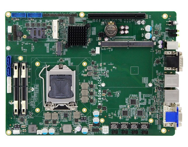
IBASE Technology Inc., a world leader in the manufacture of embedded boards and industrial computing systems, announces a new NVIDIA MXM compatible motherboard designed for AIoT applications. The MT800M-P supports the latest 8th Generation Intel® Core™ processor family, enabling customers to benefit from optimized processing and graphics performance and enhance I/O capability.
With the increasing demand of AI-enabled inference platforms, IBASE has developed the MT800M-P with an MXM socket for NVIDIA’s graphics cards (up to 190w) with GPU acceleration to harness its cutting-edge performance and responsiveness to power currently prevalent AI services such as speech recognition, image analysis, visual search and media processing.
“Combined with the latest MXM 3.0/3.1 GPU modules, the MT800M-P leverages the advantages of the NVIDIA’s GPU technology to deliver parallel processing performance with unmatched power efficiency,” said Archer Chien, Director of IBASE Solution Product Planning Department. “The MT800M-P is suitable for artificial intelligence applications in the retail, banking and transportation industries.”
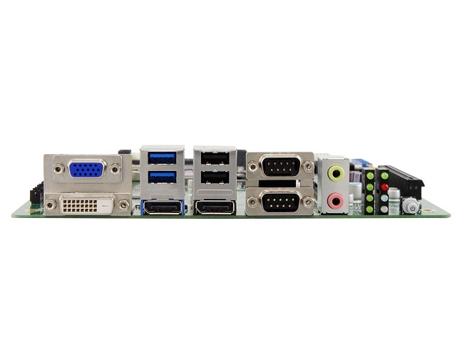
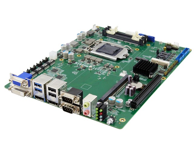
In addition to four display interfaces and 32GB system memory support, MT800M-P offers rich network connectivity with four Gigabit Ethernet and high speed I/O peripheral expandability through its six USB 3.1, two USB 2.0, two SATA III, and six serial ports. Expansion is provided by a fast PCIe x16, a Mini PCIe and an M.2 (M-key) slot. The board measures 270mm by 220mm and has 24V power input. It runs on both Windows 10 and Linux Ubuntu operating systems.
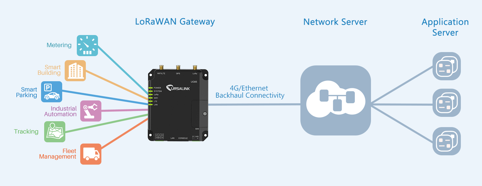
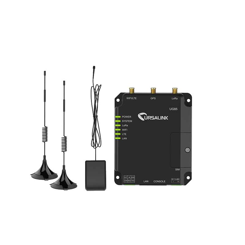
With the UG85, ICP Germany launches an intelligent and compact indoor LoRaWAN gateway that can be expanded in many ways.
The UG85 is offered with a 64-bit ARM Cortex A-53 with 800 MHz, 512MB DDR3 RAM and 8Gb eMMC flash memory. Eight LoRa channels based on the Semtech SX1301 chipset are available, which can be delivered in the frequency band for the respective target country. The UG85 supports version V1.0 Class A and C as well as V1.0.2 Class A and C and has a maximum range of 10km. A 10/100/1000 Base-T network connector, a serial RS-232 connector, a digital input and an output are available as standard.
The gateway functionality can optionally be extended by 3G/4G mobile radio with dual SIM slot and IEEE802.11 b/g/n/ac WiFi. GPS with an accuracy of less than 2.5 meters is also available as an optional extension. The UG85 supports a variety of network protocols, VPN tunnels, access authentication, firewall functionalities and management options. The serial port can be operated in transparent mode (TCP Client/Server, UDP), as Modbus Gateway (Modbus TCP on Modbus RTU) and as Modbus Master. The voltage input range of the UG85 is designed for the range from 9 to 48 volts DC. The typical consumption is 2.3 watts and under full load max. 6.5 watts.
Optionally, the PoE 802.3 af/at functionality can be added to the Ethernet connection and the UG85 can thus be expanded to a Powered Device. The housing is IP30 protected and particularly compact with 108x90x26 mm (L/W/H). Wall mounting or DIN rail mounting is easily possible. The UG85 is designed for operation in a temperature range from -40 °C to +70 °C. The UG85 can be operated in a temperature range from -40 °C to +70 °C.
From the sensor to the cloud, the UG85 offers system integrators a wide range of options for transferring their data to the cloud.
Specifications
Indoor LoRaWAN Gateway
Up to 8 simultaneous channels
Up to 10km range
Interfaces: Ethernet, WiFi, 3G/4G mobile communications
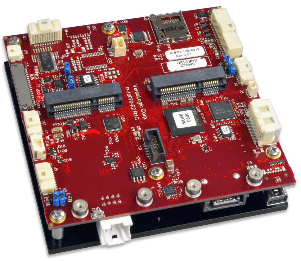
VersaLogic Corp., the embedded industry’s most trusted computer company, has announced a new compact and rugged embedded computing system with ECC memory. This is VersaLogic’s eighth product family released in the Embedded Processing Unit (EPU) format.
Named “Owl”, this new computer features error correcting memory combined with Intel®’s latest 5th generation Apollo Lake processors (dual or quad core). The Owl also includes TPM 2.0 security, on-board power conditioning, Mini PCIe expansion sockets, and analog input ports, along with standard USB and Ethernet I/O ports.
Resilient and on-guard
The Owl features soldered down ECC (error correcting) memory to enhance resilience to shock and vibration, and guard against single bit errors such as those that are likely to occur at higher altitudes. It also features on-board power conditioning which accepts 8 to 30 VDC input. This accommodates fixed and mobile 12 and 24 volt systems. Additional protection is provided against damaging transient voltages, over voltage, reverse voltage, and RF intrusion.
Small and tough
Within its 95 x 95 x 27 mm package, the Owl is an ideal balance of functionality and size for space-limited applications such as in unmanned vehicles on land, underwater, or in the air. The Owl is designed and tested for full industrial temperature (-40º to +85ºC) operation and meets MIL-STD-202H specifications for shock and vibration.
Secure
The built-in TPM 2.0 security chip provides hardware-level security for applications that require secure log-ins, encrypted data storage, protected files, etc.
Connectivity
On-board I/O includes dual Gigabit Ethernet, one USB 3.0 and four USB 2.0 ports, eight analog inputs, eight digital I/O ports, and four serial ports. A SATA interface, eMMC Flash, mSATA slot, and a microSD socket provide a range of data storage options. Dual Mini PCIe sockets accommodate plug-in A/D, Wi-Fi modems, GPS receivers, MIL-STD-1553, Ethernet, FireWire, and other mini cards.
Long-term availability
Like other VersaLogic products, the Owl is designed from the ground up for long-term availability (10+ year typical production lifecycle).
Modifications
Modifications to the off-the-shelf product are available for the Owl, even in low OEM quantities. Modifications include conformal coating, revision locks, custom labeling, customized testing and screening, etc.
Availability
Owl will be available in production volumes Q1 of 2020. Contact Sales@VersaLogic.com for pre-production opportunities.
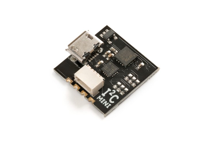
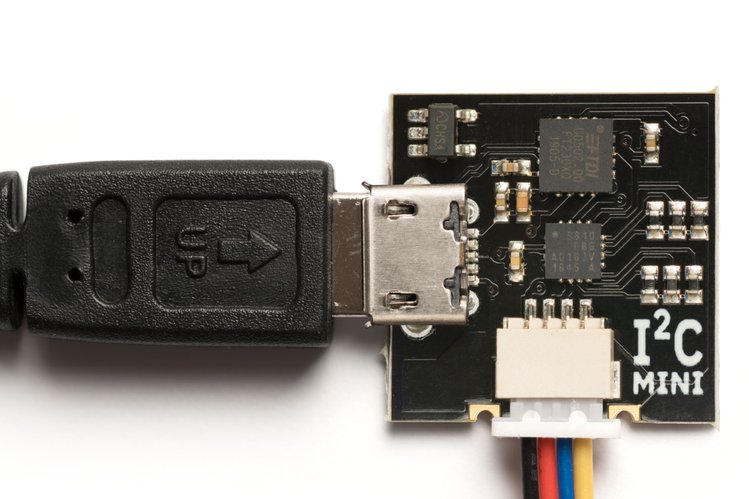
I²CMini is a USB to I²C bridge. It can drive and monitor I²C traffic and measures just 18 mm square. It has a micro USB connector, a Qwiic connector on the I²C side, and .1″ pins for a breadboard or pin header. I²CMini is 100% compatible with I²CDriver, and like I²CDriver (i2cdriver.com) it’s an easy-to-use, open source tool for controlling I²C devices. It has a GUI that works with Windows, Mac, and Linux, and it has first-class Python2/3, C/C++, and command-line tools.
I²CMini is particularly well-suited for applications like IoT and drones, cleanly separating your SBC from the I²C bus. Because it is totally compatible with I²CDriver, you can develop on the I²CDriver and deploy on the I²CMini.
Like I²CDriver, it works equally well with Windows, Mac, and Linux. It uses a standard FTDI USB serial chip to talk to the PC, so no special drivers need to be installed. The board includes a separate 3.3 V supply for your I²C sensors and peripherals.
Features
Open hardware: the design, firmware and all tools are under BSD license
Fast transfer: sustained I²C transfers at 400 and 100 kHz
I²C pullups: programmable I²C pullup resistors, with automatic tuning
Dual I²C ports: a castellated .1″ header, plus a Qwiic standard connector
Jumpers: color coded Qwiic jumper included, for instant connection
3.3 V output: output levels are 3.3 V, all are 5 V tolerant
Supports all I²C features: 7- and 10-bit I²C addressing, clock stretching, bus arbitration
Sturdy componentry: uses an FTDI USB serial adapter, and Silicon Labs automotive-grade EFM8 controller
Usage reporting: reports uptime, temperature, and running CRC of all traffic
Flexible control: GUI, command-line, C/C++, and Python 2/3 host software provided for Windows, Mac, and Linux
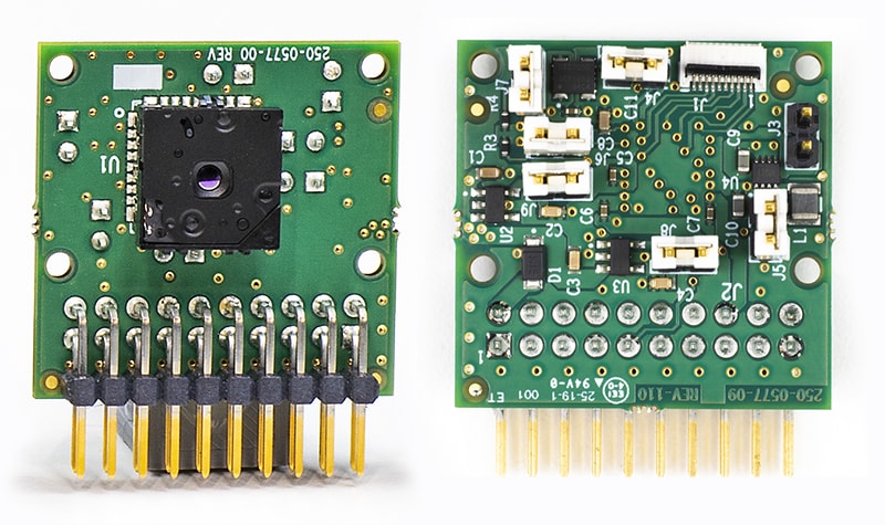
This is the brand new FLIR version of the Lepton Breakout Board. It is a very low level piece of hardware, exploiting the SPI & I2C interfaces for image and control transfer. Supports VSYNC for ensuring that video streaming has a consistent framerate.
The board is available for purchase on groupgets.com for $238.00 + shipping.
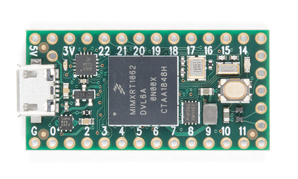
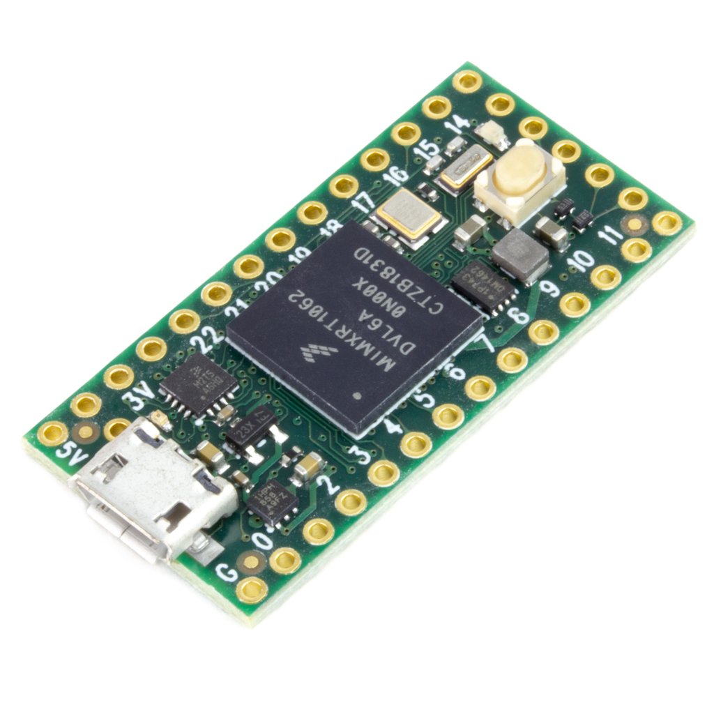
The latest offering from Teensy, Teensy 4.0 is the fastest microcontroller available today which is powered by ARM Cortex-M7 processor at 600MHz, with an NXP iMXRT1062 chip. Teensy 4.0 has the same dimensions (35 x 18 mm) of Teensy 3.2 and maintains compatibility with most of the pin functions on Teensy 3.2.
This board is based on an ARM Cortex M7 running at 600 MHz, the fastest microcontroller of 2019. The new board is also packed with two 480 Mbps USB ports, 3 digital audio interfaces, 3 CAN bus, and multiple SPI/I2C/serial interfaces backed with integrated FIFOs. For Programming, there’s an add-on to the Arduino IDE called Teensyduino.
When running at 600 MHz, Teensy 4.0 consumes approximately 100mA current. Unlike traditional microcontrollers, Teensy 4.0 can take advantage of dynamic clock scaling. Where changing the clock speed causes the wrong BaudRate and other issues on common microcontrollers, Teensy 4.0 is designed to overcome the issues to allow dynamical speed changes. Teensy 4.0 also comes with a power shut off feature. By connecting a pushbutton to the On/Off pin, the 3.3V power supply can be completely disabled by holding the button for 5 seconds and turned back on by a small button press. If a coin cell is connected to VBAT, Teensy 4.0’s RTC can keep track of date & time while the power is off.
Teensy 4.0 Front view
Specification Summary:
ARM Cortex-M7 at 600MHz
1024K RAM (512K is tightly coupled)
2048K Flash (64K reserved for recovery & EEPROM emulation)
2 USB ports, both 480MBit/sec
3 CAN Bus (1 with CAN FD)
2 I2S Digital Audio
1 S/PDIF Digital Audio
1 SDIO (4 bit) native SD
3 SPI, all with 16 word FIFO
3 I2C, all with 4 byte FIFO
7 Serial, all with 4 byte FIFO
32 general-purpose DMA channels
31 PWM pins
40 digital pins, all interrupt capable
14 analog pins, 2 ADCs on chip
Cryptographic Acceleration
Random Number Generator
RTC for date/time
Programmable FlexIO
Pixel Processing Pipeline
Peripheral cross triggering
Power On/Off management
Dimensions (35 x 18 mm)
Benchmark Result:
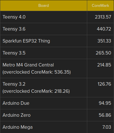
Paul Stoffregen did a benchmark testing with Teensy 4.0 along with Teensy 3.6, Teensy 3.5, Teensy 3.2, ESP32, Metro M4 Grand Central, Arduino Due, Arduino Zero, and Arduino Mega. The benchmark is performed using CoreMark . The synthetic benchmark tests performance managing linked lists, doing matrix multiplies, and executing state machine code. The result clearly shows that Teensy 4.0 outperforms all the other candidates in the test.
CoreMark benchmark result – higher is better
As to mention the possible implications of this super-fast 600 MHz microcontroller dev board we can say. It can be used for polyphonic audio synthesis, it can also help with moderately complex machine learning algorithms, and real-time audio analysis. It can also accelerate graphics operations by offloading the CPU.
The board is available at an affordable price of only 19.95 USD here.
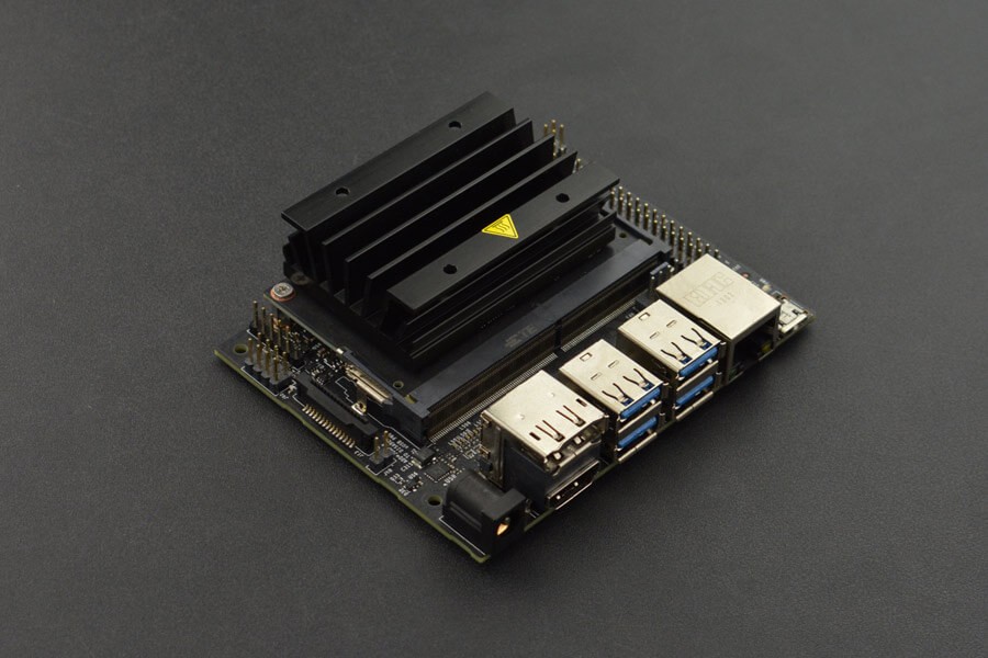
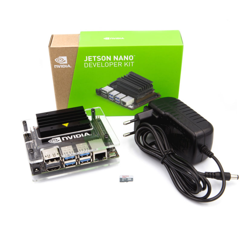
Adding muscle to its SBC and IoT solutions OKdo, part of Electrocomponents, is now selling the NVIDIA Jetson Nano Developer Kit to its range. The kit comes with out-of-the-box support for full desktop Linux, compatible with many peripherals and accessories, ready-to-use projects and tutorials to help makers get started.
The Jetson platform brings what the company says is once unimaginable artificial intelligence (AI) applications within the reach of makers, inventors, designers and engineers.
High-performance and power-efficient computing are central to the kit. It is built on the same architecture and software that powers the world’s fastest supercomputers.
It also features NVIDIA’s JetPack SDK, which is built on CUDA-X and is a complete AI software stack with accelerated libraries for deep learning, computer vision, computer graphics and multimedia processing to support the Jetson Nano.
The kit delivers 472 Gflops of computing performance, consuming as little as 5W, offering applications in object detection, video search, face recognition and heat mapping.
It supports high-resolution sensors, can process multiple sensors in parallel and has modern neural networks on each sensor stream, and it complements many popular AI frameworks, so it’s easy for developers to integrate into their products.
OKdo is focused solely on single board computing (SBC) and internet of things (IoT). It is already endorsed by leading technology companies and is committed to expanding its impressive partnership network.
“OKdo is passionate about providing SBC and IoT solutions to anyone who has an idea they want to bring to life and working with NVIDIA’s world-leading technology is perfectly in sync with that vision,” said Richard Curtin, Global SVP Technology at OKdo. “Inspiring people to create the next big thing is close to our hearts and we are hugely excited to announce this collaboration with NVIDIA to make AI more accessible for engineers globally.”
“The Jetson Nano Developer Kit is ideal for bringing the power of modern AI to a small, easy-to-use platform–enabling the development of AI-powered robots, drones, intelligent video analytics enabled-devices, AI IoT devices, and other autonomous machines,” said Murali Gopalakrishna, Head of Product Management for autonomous machines at NVIDIA. “OKdo’s strong position in the electronics development maker community will enable developers to get engaged and develop new and exciting AI applications.”
OKdo is all about bringing technology to life for everyone, whether they are makers, an entrepreneur looking to develop the next market leading product, or a design engineer who wants to use the latest technology to change the world we live in. Building an accessible range around software, hardware, services and solutions is a key component of their customer promise and the cooperation with NVIDIA fits perfectly.
The Jetson Nano Development Kit is available now at £79.99 from OKdo.com.
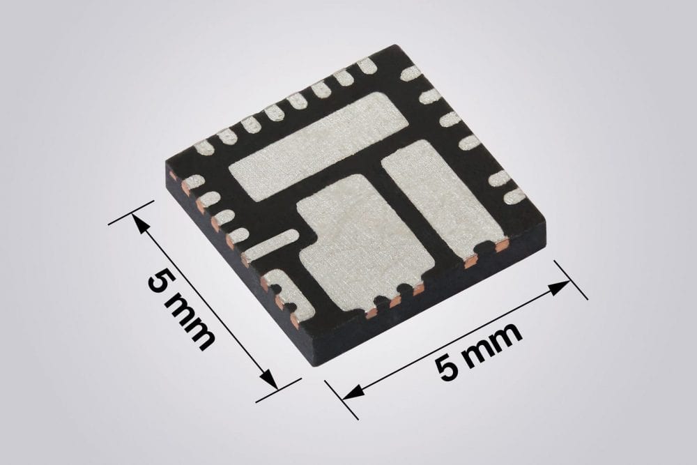
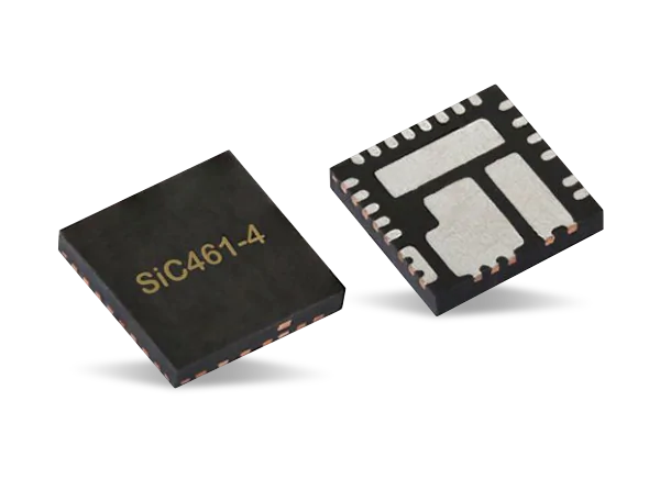
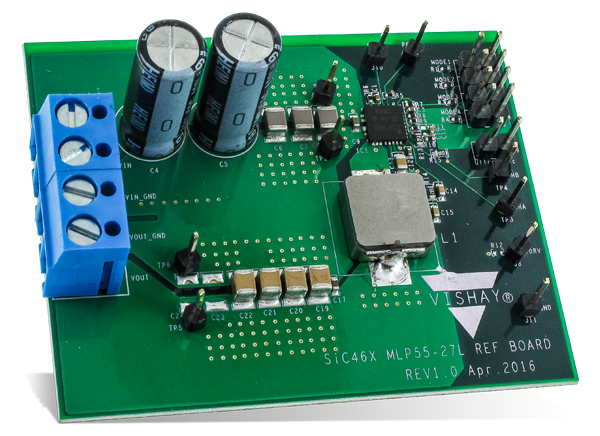
Vishay Intertechnology, Inc. has introduced two new families of 2A to 12A microBUCK® synchronous buck regulators featuring wide input voltage ranges from 4.5V to 55V (SiC476/7/8/9) and 4.5V to 60V (SiC466/7/8/9). Combining rugged high-performance n-channel trench MOSFETs with a controller in the compact 5×5 PowerPAK® package, the Vishay Siliconix devices deliver high efficiency and power density, while their internal compensation reduces the external component count.
The microBUCK regulators announced today share the same controller IC and package outline while providing a range of MOSFET ratings from which designers can select the best combination of cost and performance.
Offering a low 156µA operating current and peak efficiency up to 98%, the regulators released today allow designers to increase power density by reducing power losses. Combined with the superior thermal design of the 5mm x 5mm PowerPAK package, their efficiency enables cooler operation for improved long-term reliability while eliminating the need for a heatsink.
The microBUCK wide safe operating area gives designers flexibility to support a wide range of operating temperature and current requirements. This allows designers to shrink the PCB size, simplify thermal management, and reduce system costs.
With their input voltage ranges and an adjustable output voltage from 24V down to 0.8V, SiC466/7/8/9 and SiC476/7/8/9 family regulators are designed for a wide range of applications. These include dc-dc converters for industrial and factory automation, home automation, industrial computing, base station power supplies, 5G network equipment and small cells, wall transformer regulation, robotics, drones, battery management systems, power tools, and vending, ATM, and slot machines.
The new SiC46x family devices are the 2A SiC469, 4A SiC468, 6A SiC467, and 10A SiC466, while the new SiC47x family devices are the 3A SiC479, 5A SiC478, 8A SiC477, and 12A SiC476. All are footprint-compatible to provide a scalable solution to designers.
Highly configurable, the regulators feature adjustable switching frequencies from 100 kHz to 2 MHz, adjustable soft start and current limits, and two operating modes: forced continuous conduction or power save. The internal compensation in both families eliminates the need for external RC networks.
The microBUCK COT architecture delivers ultrafast transient response with minimum output capacitance and tight ripple regulation at light loads. It also enables loop stability regardless of the type of output capacitor used, including low ESR ceramic capacitors.
The regulators integrate a robust protection feature set, including output overvoltage protection, output undervoltage protection, overcurrent circuit protection, short circuit protection with auto retry, over temperature protection, and a power good flag.
Samples and production quantities of the SiC466/7/8/9 and SiC476/7/8/9 families are available now, with lead times of 12 weeks. Pricing for U.S. delivery only starts at $1.80 per piece in 1000-piece quantities.
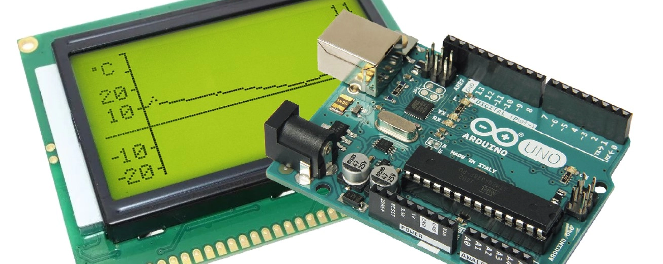
Using the tiny Arduino Uno, you can build all manner of really neat small projects at modest cost. This one is a simple temperature recorder that shows on a display screen the values measured during the past 24 hours. Of particular note is the software, which manages all of the operations without recourse to external libraries.
The recorder described in this article measures the temperature over the course of a day and displays the readings on a graphic display screen. When a new measured value is added, the displayed curve is shifted one pixel to the left, so that the oldest value disappears and the newest reading appears. The interval between measurements can be changed easily to record more rapid temperature changes, for example in process control applications.
The project software, with comments, can be downloaded by clicking on DOWNLOAD ATTACHMENT below.
Over time we have built quite a number of data logger projects, but the emergence of more modern development boards, sensors and platforms mean there is an opportunity to add several new features to data-logging devices. For today’s tutorial, we are going to build a datalogger based on one of Arduino’s recent boards; the Nano 33 Sense IoT board.
YADL Display
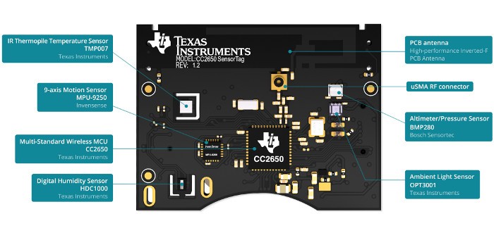
The project basically involves the logging of temperature, pressure, humidity, and light intensity data collected from the Texas Instrument’s sensorTag to an SD Card with the Nano 33 IoT board in between. The TI SensorTag packs many different sensors into a small battery-powered unit and uses Bluetooth Low Energy (BLE) to communicate readings to connected devices like mobile phones, tablets or microcontrollers. It belongs to a new class of sensors that are developed to reduce power consumption, improve portability and eradicate compatibility issues between sensors and microcontrollers. Sensors like the SensorTag are self-contained and possess all they need to exist alone, collecting data and just streaming to whoever calls over BLE. Other communication protocols used by such sensors include BLE, Zigbee, LoRa, and even WiFi.
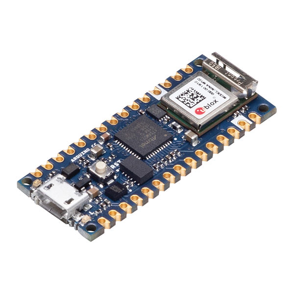
The Nano 33 IoT Board comes with onboard wireless features like WiFi and Bluetooth BLE along with an onboard RTC all of which makes it the perfect data-gathering device. The presence of the onboard BLE and the ability of the sensorTag to communicate its data over BLE means we can easily query the SensorTag for the data we require and it will automatically be sent over WiFi. The data received can then be logged on the SD Card.
Nano 33 IoT
At the end of today’s tutorial, you would know how to work with the Nano 33 IoT board and also use the TI Sensor Tag.
Required Components
The following components are required to build today’s project;
For our own build, we will use the Nano 33 sense IoT board, but since it is compatible with the MKR WiFi 1010, on the level at which we will be using it, you can choose to work with the MKR as well.
The exact version of these components used for this tutorial can be bought from the links attached to them.
Schematics
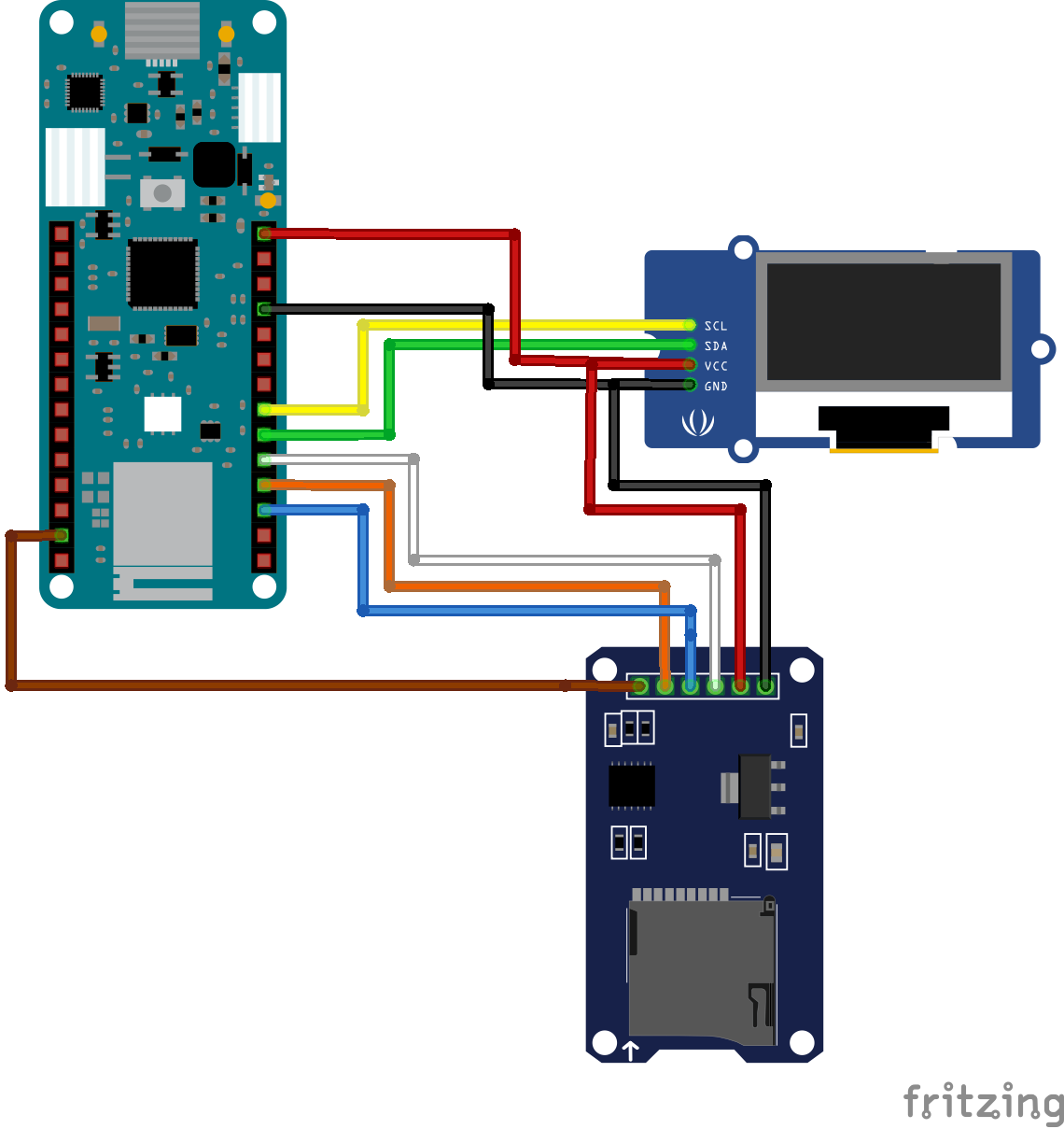
The schematics for this project is quite straight forward. We will connect the SD Card module to the Nano 33 IoT Board via its SPI pins while the OLED display will be connected over I2C. The sensor tag is self-contained and communicates with the microcontroller via Bluetooth as such there will be no physical connection between it and the Nano 33 IoT board.
The schematic showing how the components are connected is provided in the image below:
Schematics
To make the schematics easier to follow, a pin-pin description of the connection between the components is provided below.
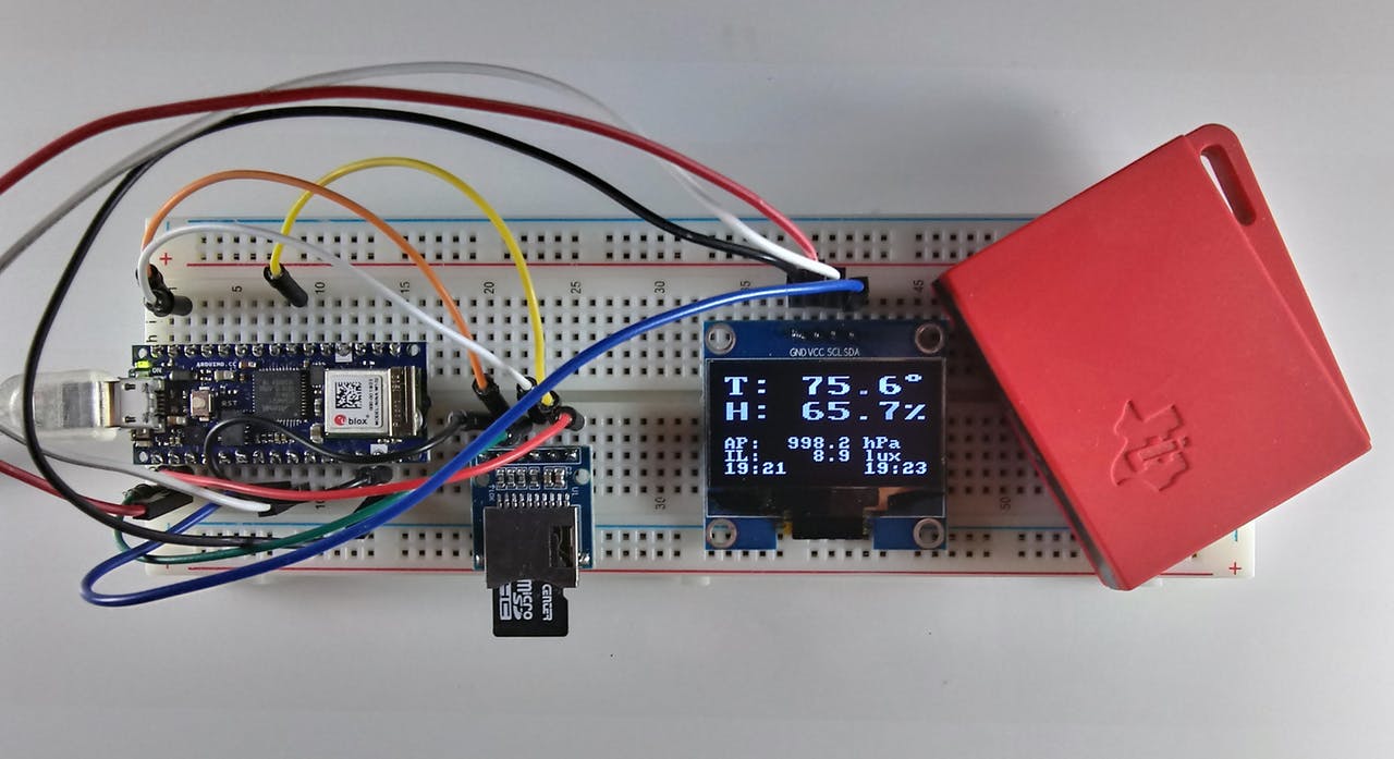
Go over the connections again to ensure everything is as it should be before proceeding to the next section. The setup with everything properly connected should look like the image below.
Code
Based on the goals of the project described under the introduction section, the code for this project is required to query the sensor tag to measure the temperature in Fahrenheit, Relative humidity, barometric pressure, and illumination level of the environment. All of these data are then logged (optional) on the SD Card and displayed on the OLED.
To reduce the amount of work involved, and help optimize the code, we will use Arduino libraries like; the WiFiNINA v1.40 library, the ArduinoBLE library (v1.1.1), RTCZero library (1.6.0), the SD library (v1.2.3), and the U8g2 library. All the libraries can either be installed via the Arduino IDE or downloaded from the links attached to them. The versions of the libraries are added so you can get their exact version as some of them have backward compatibility issues so getting an older or newer version of that same library might not work.
The WiFiNINA library is used to perform all the WiFi related tasks associated with the project while the ArduinoBLE Library facilitates interaction with the SensorTag. The RTCZero library helps with tracking time so the data stored can be timestamped while the SD library facilitates logging the data and the U8G2 library handles the display of that data on the OLED.
With all the libraries installed, we can now proceed to write the code for the project.
As usual, I will do a quick run through the code to explain parts of it that could be difficult.
We start the code by including all the required libraries. These are the same libraries discussed above.
include <WiFiNINA.h>
#include <RTCZero.h>
#include <ArduinoBLE.h>
#include <SPI.h>
#include <SD.h>
#include <U8x8lib.h>
#include <avr/dtostrf.h> // needed for MKR1010
Next, we create an instance of some of the libraries to be used to reference them in our code.
Next, we create a global structure to hold the data obtained from the SensorTag.
// Global structure to hold the sensor data
struct DATA {
  float tem;     // HDC1000 temperature F
  float hum;     // HDC1000 relative humidity %RH
  float bptemp;  // BMP 280 die temperature F
  float bp;      // BMP 280 barometric pressure in hectoPascals (1 hPa = 100 Pa)
  float li;      // OPT3001 lux
  float temd;    // TMP007 die temperature F
  float temo;    // TMP007 object temperature F
};
We also create a bunch of other variables all of which are properly commented with the purpose which they serve properly stated.
// lcd vars
char degree[] = {0xb0, 0x00};
char percent[] = {0x25, 0x00};
char p_buffer[12] = {0, 0, 0, 0, 0, 0, 0, 0, 0, 0, 0, 0};

// clock change catcher
int lastmin;

// for RTC
unsigned long epoch;
int numberOfTries = 0, maxTries = 6;

int status = WL_IDLE_STATUS;  // WiFiNINA use

// Common user-changeable switches
const int GMT = -4; //change this to adapt it to your time zone
byte SDswitch = 1;  // SDswitch 1=ON (write to SD) or 0 (Do not write to SD)
char fname[] = "STDATA.txt"; // data log file Name

//period defines the length of time between measurements in milliseconds
// note that this does not includes delays for sensor reads (~8.7 sec)
long period = 600000L; // 10 minutes
//long period = 5000L;  // 5 sec for testing
Next, we specify the credentials (SSID and Password) of your WiFi access point through which the device is able to connect to the internet. Provide the Key Index if the WiFi security is WEP.
char ssid[] = "";   // your network SSID (name)
char pass[] = "";   // your network password (use for WPA, or use as key for WEP)
int keyIndex = 0;             // your network key Index number (needed only for WEP)
Next, we create SensorTag Characteristics definition to help us pull data from specific sensors. The description for each of the characteristic definitions can be found in sensorTag’s datasheet. You can go through it to know what to call to get data from a particular sensor.
With this done, we are now ready to write the void setup() function.
We start the function by initializing the OLED via the U82g library, setting the font with which text is displayed and displaying a string “YADL Starting..” to serve as a splash screen.
Next, we initialize serial communication to provide an avenue for debugging via the serial monitor. The code is delayed for a few seconds after every restart to allow the user to launch the serial monitor before data display commences.
#ifdef DEBUG
  Serial.begin(9600);
  delay(5000);  // delay for user to open the serial monitor
  Serial.println("YADL MKR1010/NANO IOT 33 SensorTag Data Logger");
  Serial.println();
#endif
The use of the SD Card is optional so next, we write the code to check/state the users preferred option. If you do not want to use an SD card to save the data, you can eliminate that function by setting the value of the SDswitch variable to “0” but by default, the option to write to the SD is on(“1”). If the option is 1, then the code checks to confirm that an SD card is inserted and working. If not, an error (“No SD Card”) will be displayed and execution goes no further, but if the Card is present and functional, the system continues its operation.
 // check the SD card
  if (SDswitch == 1) {
    if (!SD.begin(4)) {
      u8x8.drawString(0, 2 , "No SD card!");
      u8x8.drawString(0, 3 , "Terminal Error!");
#ifdef DEBUG
      Serial.println("SD Card initialization failed!");
#endif
      while (1);
    }
    else {
      u8x8.drawString(0, 2 , "SD card found. ");
      delay(2000);    // to let user know
      u8x8.drawString(0, 2 , "               ");
#ifdef DEBUG
      Serial.println("SD Card found");
#endif
    }
  }
  else {
    u8x8.drawString(0, 2 , "No SD card");
    u8x8.drawString(0, 3 , "option");
    delay(2000);    // to let user know
    u8x8.drawString(0, 2 , "          ");
    u8x8.drawString(0, 3 , "      ");
#ifdef DEBUG
    Serial.println("No SD Card option");
#endif
  }
Next, we confirm the active status of the onboard WIFi module and if available we connect to the access point using the credentials provided earlier. The connection status is displayed and the board’s WiFi capability is used to contact a time server to get the current epoch. Note that you can correct this epoch for your time zone and DST setting (see program variable GMT). Once the epoch is obtained, the onboard real-time-clock (RTC) is set and used to keep the time.
  // check if the WiFi module works
  if (WiFi.status() == WL_NO_SHIELD) {
#ifdef DEBUG
    Serial.println("WiFi shield not present");
#endif
    u8x8.drawString(0, 1 , "NO WiFi!");
    u8x8.drawString(0, 2 , "Terminal Error!");
    // don't continue:
    while (true);
  }

  // attempt to connect to WiFi network:
  u8x8.drawString(0, 2 , "Connecting.....");
  while ( status != WL_CONNECTED) {
#ifdef DEBUG
    Serial.print("Attempting to connect to SSID: ");
    Serial.println(ssid);
#endif
    // Connect to WPA/WPA2 network. Change this line if using open or WEP network:
    status = WiFi.begin(ssid, pass);
    delay(10000); // wait 10 seconds for connection:
  }
  u8x8.drawString(0, 3 , "Connected!     ");
#ifdef DEBUG
  printWiFiStatus(); // you're connected now, so print out the status:
#endif
  rtc.begin();
  do {
    epoch = WiFi.getTime();
    numberOfTries++;
  }
  while ((epoch == 0) && (numberOfTries < maxTries));

  if (numberOfTries == maxTries) {
    u8x8.drawString(0, 4 , "NTP Unreachable");
    u8x8.drawString(0, 5 , "TERMINAL ERROR!");
#ifdef DEBUG
    Serial.print("NTP unreachable!!");
#endif
    while (1);
  }
  else {
    u8x8.drawString(0, 4 , "Got NTP Epoch  ");
    epoch = epoch + (GMT * 3600UL); // adjust offset for TZ/DST
    rtc.setEpoch(epoch);
#ifdef DEBUG
    Serial.print("Epoch received: ");
    Serial.print(epoch);
    Serial.print(" ");
    printP02D(rtc.getHours());
    Serial.print(":");
    printP02D(rtc.getMinutes());
    Serial.print(":");
    printP02D(rtc.getSeconds());
    Serial.print(" ");
    Serial.print(rtc.getDay());
    Serial.print("/");
    Serial.print(rtc.getMonth());
    Serial.print("/");
    Serial.print(rtc.getYear());
    Serial.println();
#endif
After the time epoch has been received and the RTC corrected, WiFi is ended and BLE begins. Since both of the boards have WiFi and BLE capability, this is easily accomplished.
    WiFi.end();
    delay(15000);
    u8x8.drawString(0, 5 , "WiFi Ended     ");
    u8x8.drawString(0, 6 , "Starting BLE   ");
    delay(2000); // to see it on the screen
#ifdef DEBUG
    Serial.println("WiFi.end executed");
#endif
  }
  // Try to initialize BLE
  if (!BLE.begin()) {
    Serial.println("Terminal Error: Could not start BLE!");
    u8x8.clear();
    u8x8.drawString(0, 0 , "BLE Start Fail");
    u8x8.drawString(0, 1 , "Terminal Error!");
    while (1);
  }
Finally, for the void setup(), the BLE is put into scan mode and the user is notified of the mode via the OLED display.
Next, we move to the void loop() function. We start the function by running scans to see if a Bluetooth device is available. If it is, then we check if it is the SensorTag and we attempt to connect when it is found.
void loop() {
  long lastMillis = 0;  // for period test
  long nowMillis = 0;   // for period test

  // check if a peripheral has been discovered
  peripheral = BLE.available();
  if (peripheral) {
    // discovered a peripheral, print out address and local name
#ifdef DEBUG
    Serial.print("Found ");
    Serial.print(peripheral.address());
    Serial.print(" '");
    Serial.print(peripheral.localName());
    Serial.println("' ");
#endif
    if (peripheral.localName() == "CC2650 SensorTag") {
      BLE.stopScan(); // stop scanning
      // connect to the peripheral
      u8x8.drawString(0, 1 , "Connecting....");
#ifdef DEBUG
      Serial.print("Connecting to SensorTag ...");
#endif
      if (peripheral.connect()) {
        u8x8.drawString(0, 2 , "Connected.....");
#ifdef DEBUG
        Serial.println("Connected...");
#endif
With the SensorTag now connected, we proceed to read the various sensors and write the data to the SD Card using the Write_SDdata function.
while (peripheral.connected()) {
    read_BP(peripheral);
    read_OPT(peripheral);
    read_IRT(peripheral);
    read_HUM(peripheral);
    if (SDswitch) write_SDdata(); // write data to sd card
    // screen for debug no print here as well
At this point, it is important to note that there are different versions of the SensorTag CC2650 and some newer versions may not include the TMP007 sensor like the one used for this project. If that is the case, all you need do is comment out the program references to that unavailable sensor.
With the data logged on the SD, it is then displayed on the OLED and also on the serial monitor.
#ifdef DEBUG
      print_data();
#endif
      print_screenValues();
      printclockD(1); // Update sensor clock
      printclockD(2); // update current clock
      lastmin = rtc.getMinutes();
      lastMillis = millis();
      // stay here until the period is up
      // update current time here
      while ( ( (nowMillis = millis()) - lastMillis) <= period) {
        // need to update the clock here
        if (lastmin != rtc.getMinutes()) {
          lastmin = rtc.getMinutes();
          printclockD(2); // update current clock
        }
      }
    }
The buffer is cleared and the scan process is repeated.
The remaining part of the sketch represents the code snippets for the functions that were called within the setup() and loop() functions.
// BLE SensorTag routines
void do_discovery(BLEDevice peripheral) {
  // discover the peripheral's attributes that we want
  // barometric
#ifdef DEBUG
  Serial.print("Discovering attributes for Barometric Pressure service ...");
#endif
  if (peripheral.discoverService("f000aa40-0451-4000-b000-000000000000")) {
#ifdef DEBUG
    Serial.println("discovered");
#endif
    BPConCharacteristic = peripheral.characteristic("f000aa42-0451-4000-b000-000000000000");
    BPValCharacteristic = peripheral.characteristic("f000aa41-0451-4000-b000-000000000000");
  }
  else  {
#ifdef DEBUG
    Serial.println("ERROR: Barometric Pressure service discovery failed.");
#endif
    peripheral.disconnect();
    return;
  }
  // discover the peripheral's attributes that we want
  // optical sensor
#ifdef DEBUG
  Serial.print("Discovering attributes for Luxometer service ...");
#endif
  if (peripheral.discoverService("f000aa70-0451-4000-b000-000000000000")) {
#ifdef DEBUG
    Serial.println("discovered");
#endif
    OPTConCharacteristic = peripheral.characteristic("f000aa72-0451-4000-b000-000000000000");
    OPTValCharacteristic = peripheral.characteristic("f000aa71-0451-4000-b000-000000000000");
  }
  else  {
#ifdef DEBUG
    Serial.println("Error: Luxometer service discovery failed.");
#endif
    peripheral.disconnect();
    return;
  }
  // IR
#ifdef DEBUG
  Serial.print("Discovering attributes for Infrared service ...");
#endif
  if (peripheral.discoverService("f000aa00-0451-4000-b000-000000000000")) {
#ifdef DEBUG
    Serial.println("discovered");
#endif
    IRTConCharacteristic = peripheral.characteristic("f000aa02-0451-4000-b000-000000000000");
    IRTValCharacteristic = peripheral.characteristic("f000aa01-0451-4000-b000-000000000000");
  }
  else  {
#ifdef DEBUG
    Serial.println("Error: Infrared service discovery failed.");
#endif
    peripheral.disconnect();
    return;
  }
  // humidity
#ifdef DEBUG
  Serial.print("Discovering attributes for Humidity service ...");
#endif
  if (peripheral.discoverService("f000aa20-0451-4000-b000-000000000000")) {
#ifdef DEBUG
    Serial.println("discovered");
#endif
    HUMConCharacteristic = peripheral.characteristic("f000aa22-0451-4000-b000-000000000000");
    HUMValCharacteristic = peripheral.characteristic("f000aa21-0451-4000-b000-000000000000");
  }
  else  {
#ifdef DEBUG
    Serial.println("Error: Humidity service discovery failed.");
#endif
    peripheral.disconnect();
    return;
  }
}

// Sensor reads
void read_BP(BLEDevice peripheral) {
  uint8_t holdvalues[6];

  if (peripheral.connected()) {
    // wake up the sensor
    BPConCharacteristic.writeValue(sensorOn);
    delay(1200); // wait for the sensor to do a read
    BPValCharacteristic.readValue(holdvalues, 6);
    unsigned long rawbptemp = (holdvalues[2] * 65536) + (holdvalues[1] * 256) + holdvalues[0];
    unsigned int rawbp = (holdvalues[5] * 65536) + (holdvalues[4] * 256) + holdvalues[3];
    // sleep sensor
    BPConCharacteristic.writeValue(sensorOff);
    // calculate temperature and pressure final values
    float bptemp = ((double)rawbptemp / 100.0);
    bptemp = ((bptemp * 9.0) / 5.0) + 32.0; // convert to F - comment out to leave at C
    float bp = ((double)rawbp / 100.0);
    // save into the structure
    SensorData.bp = bp;
    SensorData.bptemp = bptemp;
  }
  else {
#ifdef DEBUG
    Serial.println(" *not connected* ");
#endif
  }
}

void read_OPT(BLEDevice peripheral) {
  // in this version the characteristic's value is read directly
  // into rawlux and then processed. No array is used.

  uint16_t rawlux;

  if (peripheral.connected()) {
    // wake up the sensor
    OPTConCharacteristic.writeValue(sensorOn);
    delay(1200); // wait for the sensor to do a read
    OPTValCharacteristic.readValue(rawlux);
    OPTConCharacteristic.writeValue(sensorOff); // sleep sensor
    // calculate lux final value
    unsigned int m = rawlux & 0x0FFF;
    unsigned int e = (rawlux & 0xF000) >> 12;
    float lux = (m * (0.01 * pow(2.0, e)));
    // save into the structure
    SensorData.li = lux;
  }
  else {
#ifdef DEBUG
    Serial.println(" *not connected* ");
#endif
  }
}

void read_IRT(BLEDevice peripheral) {
  uint8_t holdvalues[4];

  if (peripheral.connected()) {
    // wake up the sensor
    IRTConCharacteristic.writeValue((uint8_t) 0x01);
    delay(1200); // wait for the sensor to do a read
    IRTValCharacteristic.readValue(holdvalues, 4);
    unsigned int rawobj = (holdvalues[0]) + (holdvalues[1] * 256);
    unsigned int rawamb = (holdvalues[2]) + (holdvalues[3] * 256);
    IRTConCharacteristic.writeValue(sensorOff); // sleep sensor
    // calculate final temperature values
    const float SCALE_LSB = 0.03125;
    int it = (int)( rawobj >> 2);
    float IRTo = ( (float)it) * SCALE_LSB;
    IRTo = ( (IRTo * 9.0) / 5.0 ) + 32.0; // convert to F - comment out to leave at C
    it = (int)(rawamb >> 2);
    float IRTa = (float)it * SCALE_LSB;
    IRTa = ( (IRTa * 9.0) / 5.0) + 32.0; // convert to F - comment out to leave at C
    // save into the structure
    SensorData.temd = IRTa;
    SensorData.temo = IRTo;
  }
  else {
#ifdef DEBUG
    Serial.println(" *not connected* ");
#endif
  }
}

void read_HUM(BLEDevice peripheral) {
  uint8_t holdvalues[4]; // hold the characteristic's bytes

  if (peripheral.connected()) {
    // wake up sensor
    HUMConCharacteristic.writeValue(sensorOn);
    delay(1200); // wait for the sensor to do a read
    HUMValCharacteristic.readValue(holdvalues, 4);
    HUMConCharacteristic.writeValue(sensorOff); // sleep sensor
    unsigned int rawtem = (holdvalues[0]) + (holdvalues[1] * 256);
    unsigned int rawhum = (holdvalues[2]) + (holdvalues[3] * 256);
    // calculate final temperature and relative humidity values
    float temp = (rawtem / 65536.0) * 165.0 - 40.0;
    temp = ((temp * 9.0) / 5.0) + 32.0; // convert to F - comment out to leave at C
    float hum = ((double)rawhum / 65536.0) * 100.0;
    // save into the structure
    SensorData.tem = temp;
    SensorData.hum = hum;
  }
  else {
#ifdef DEBUG
    Serial.println(" *not connected* ");
#endif
  }
}

// Print serial and screen and write SD routines
void print_data() {
  // Print the data to the serial moniter
  // NOTE: the time vars could be slightly different then the SD card
  // since they are two different routines but the Serial prints are
  // mainly for debugging

  String separator = ", ";
  // Data Line as follow (with comma separator):
  // epoch day, month, year, hours, minutes, seconds, HDC1000 temp, HDC1000 hum,
  // BMP280 pressure, BMP280 tem, OPT3001 light (lux), TMP007 temp, TMP0007 object temp
#ifdef DEBUG
  Serial.print(rtc.getEpoch());
  Serial.print(separator);
  Serial.print(rtc.getDay());
  Serial.print(separator);
  Serial.print(rtc.getMonth());
  Serial.print(separator);
  Serial.print(rtc.getYear());
  Serial.print(separator);
  printP02D(rtc.getHours());
  Serial.print(separator);
  printP02D(rtc.getMinutes());
  Serial.print(separator);
  printP02D(rtc.getSeconds());
  Serial.print(separator);
  Serial.print(SensorData.tem);
  Serial.print(separator);
  Serial.print(SensorData.hum);
  Serial.print(separator);
  Serial.print(SensorData.bp);
  Serial.print(separator);
  Serial.print(SensorData.bptemp);
  Serial.print(separator);
  Serial.print(SensorData.li);
  Serial.print(separator);
  Serial.print(SensorData.temo);
  Serial.print(separator);
  Serial.print(SensorData.temd);
  Serial.println();
  // end of data line
#endif
}

void write_SDdata() {
  // Write the data to the SD card
  String separator = ", ";

  // Data Line as follow (with comma separator):
  // epoch day, month, year, hours, minutes, seconds, HDC1000 temp, HDC1000 hum,
  // BMP280 pressure, BMP280 tem, OPT3001 light (lux), TMP007 temp, TMP0007 object temp
  // open the file
  SDF = SD.open(fname, FILE_WRITE);
  if (!SDF) {
    // terminal error if we can't open the SD File (we already initialized)
    u8x8.clearDisplay();
    u8x8.drawString(0, 2 , "SD Card    ");
    u8x8.drawString(0, 3 , "Terminal Error!");
#ifdef DEBUG
    Serial.println("SD card write failure!");
#endif
    while (1);
  }
  else {
    // write the separator-delimited data line
    // comment out what you don't want e.g.,
    // epoch, day,mon,year,hour,min,sec, HDC tem, HDC hum, AP, BMP tem, Illum, TMP obj Tem, TMP tem
    SDF.print(rtc.getEpoch());
    SDF.print(separator);
    SDF.print(rtc.getDay());
    SDF.print(separator);
    SDF.print(rtc.getMonth());
    SDF.print(separator);
    SDF.print(rtc.getYear());
    SDF.print(separator);
    SDF.print(rtc.getHours());
    SDF.print(separator);
    SDF.print(rtc.getMinutes());
    SDF.print(separator);
    SDF.print(rtc.getSeconds());
    SDF.print(separator);
    SDF.print(SensorData.tem);
    SDF.print(separator);
    SDF.print(SensorData.hum);
    SDF.print(separator);
    SDF.print(SensorData.bp);
    SDF.print(separator);
    SDF.print(SensorData.bptemp);
    SDF.print(separator);
    SDF.print(SensorData.li);
    SDF.print(separator);
    SDF.print(SensorData.temo);
    SDF.print(separator);
    SDF.print(SensorData.temd);
    SDF.println();  // Windows cr/lf
    SDF.close();
  }
}

void print_screenT() {
  // print the LCD template
  u8x8.setFont(u8x8_font_px437wyse700a_2x2_f);   // large for Tem/Hum
  u8x8.drawString(0, 0, "T:");
  u8x8.drawUTF8(14, 0, degree);
  u8x8.drawString(0, 2, "H:");
  u8x8.drawUTF8(14, 2, percent);
  // back to smaller font for tyhe rest
  u8x8.setFont(u8x8_font_amstrad_cpc_extended_f);
  u8x8.drawString(0, 5, "AP:");
  //u8x8.drawString(0, 5, "BP:    0123 hPa");
  u8x8.setCursor(10, 5);
  u8x8.print(" hPa");
  u8x8.drawString(0, 6, "IL:");
  u8x8.setCursor(10, 6);
  u8x8.print(" lux");
  // alternative times current left
  u8x8.drawString(0, 7, "00:00");
  u8x8.drawString(11, 7, "00:00");
}

void print_screenValues() {
  float Dtem, Dhum, Dap, Dli;
  // call this *after* sensor structure has been updated
  // first update the logged time? need small font
  u8x8.setFont(u8x8_font_px437wyse700a_2x2_f);   // large for Tem/Hum
  // temperature
  // sensor error check NOTE: read values will be printed to screen and SD
  Dtem = SensorData.tem;
  if (Dtem > 999.9) Dtem = 999.9;
  if (Dtem < -99.9) Dtem = -99.9;
  dtostrf(Dtem, 5, 1, p_buffer); // convert to 5 chars 1 after decimal
  u8x8.setCursor(4, 0);
  u8x8.print(p_buffer);
  //u8x8.drawUTF8(14, 0, degree); degree sign has been done in
  // humidity
  // sensor error check
  Dhum = SensorData.hum;
  if (Dhum > 100.0) Dhum = 100.0;
  if (Dhum < 0.0) Dhum = 0.0;
  dtostrf(Dhum, 5, 1, p_buffer); // convert to 5 chars 1 after decimal
  u8x8.setCursor(4, 2);
  u8x8.print(p_buffer);
  //u8x8.drawUTF8(14, 2, percent);  already done in template print
  // back to smaller font for tyhe rest
  u8x8.setFont(u8x8_font_amstrad_cpc_extended_f);
  // barometric pressure
  // sensor error check
  Dap = SensorData.bp;
  if (Dap < 750.0) Dap = 000.0;
  if (Dap > 1200.0) Dap = 9999.9;
  dtostrf(Dap, 7, 1, p_buffer); // convert to 7 chars 1 after decimal
  u8x8.setCursor(3, 5);
  u8x8.print(p_buffer);
  // Illuminance
  // sensor error check
  Dli = SensorData.li;
  if (Dli > 99999.9) Dli = 99999.9;
  if (Dli < 0.0) Dli = 0;
  dtostrf(Dli, 7, 1, p_buffer); // convert to 7 chars 1 after decimal
  u8x8.setCursor(3, 6);
  u8x8.print(p_buffer);
}

void printclockD(byte side) {
  // print the HH:SS of the current clock on the right or left side of the LCD
  // must be in a small font! (could do this as a switch case)
int hourT,minT;

  switch (side) {
    case 1: //left side
      u8x8.setCursor(0, 7);
      hourT = rtc.getHours();
      if (hourT < 10) { // pad hours <10
        u8x8.drawString(0, 7 , "0");
        u8x8.setCursor(1, 7);
        u8x8.print(hourT);
      }
      else {
        u8x8.print(hourT);
      }
      // note the ':' is from the template
      u8x8.setCursor(3, 7);
      minT = rtc.getMinutes();
      if (minT < 10) { // pad seconds <10
        u8x8.drawString(3, 7 , "0");
        u8x8.setCursor(4, 7);
        u8x8.print(minT);
      }
      else {
        u8x8.print(minT);
      }
      break;
    case 2: // right side
      u8x8.setCursor(11, 7);
      hourT = rtc.getHours();
      if (hourT < 10) { // pad hours <10
        u8x8.drawString(11, 7 , "0");
        u8x8.setCursor(12, 7);
        u8x8.print(hourT);
      }
      else {
        u8x8.print(hourT);
      }
      // note the ':' is from the template
      u8x8.setCursor(14, 7);
      minT = rtc.getMinutes();
      if (minT < 10) { // pad secondss <10
        u8x8.drawString(14, 7 , "0");
        u8x8.setCursor(15, 7);
        u8x8.print(minT);
      }
      else {
        u8x8.print(minT);
      }
      break;
    default:  // can add other options
      // statements
      break;
  }
}

void printWiFiStatus() {
  // note: this will only be called if DEBUG is defines
  Serial.print("SSID: ");
  Serial.println(WiFi.SSID());
  IPAddress ip = WiFi.localIP();
  Serial.print("IP Address: ");
  Serial.println(ip);
  long rssi = WiFi.RSSI();
  Serial.print("signal strength (RSSI):");
  Serial.print(rssi);
  Serial.println(" dBm");
}

void printP02D(int number) {
  if (number < 10) Serial.print('0');
  Serial.print(number);
}
The code is a bit bulky as such, the complete code for the project is attached under the download section.
Demo
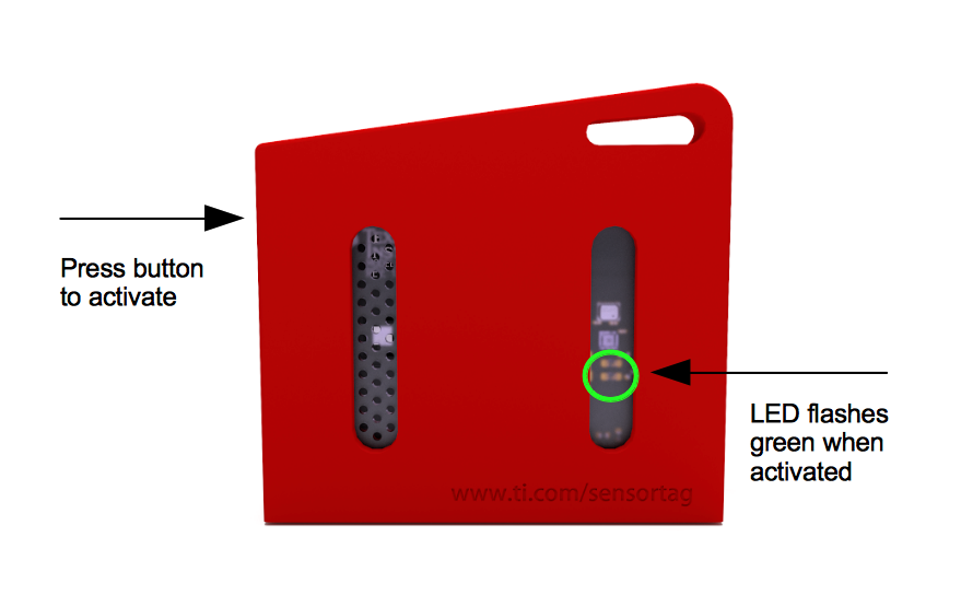
With the sketch complete, verify it to ensure there are no errors, then go over the schematics once again to ensure everything is as it should be. With that done, connect the Nano 33 IoT or the MKR WiFi 1010 to your computer and upload the sketch to it. As soon as the upload is complete, open your serial monitor for debugging, and turn on the SensorTag ensuring its within reasonable distance for Bluetooth connection to your Nano 33 IoT setup.
Turn On the SensorTag
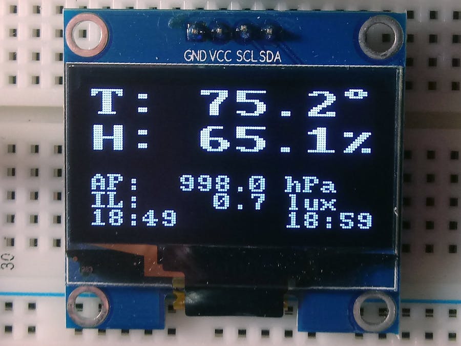
From the serial monitor and the OLED, you should see the SensorTag connect to the Nano 33 sense IoT and you should see the data displayed on the OLED as shown below.
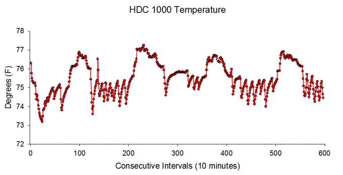
The data should also now be stored in a CSV format on the attached SD card too with timestamps that reflect the time as maintained by the RTC, and you should be able to plot it as shown in the image below.
Going Forward
While IoT provides a good way to receive data immediately and perform analysis in real-time, there are situations where it becomes impractical to send the data in real-time. For such a situation the data can be logged and then transmitted in due time, which can be achieved with a setup similar to the one described in this tutorial. Also, more sensors like the SensorTags are being developed with some based on connectivity solutions with longer ranges like LoRa. Having all of these in place means a scenario where a single datalogger can be used for multiple sensors that can be achieved.
That’s all for today’s project. Thanks for building along. Feel free to reach out to me with whatever questions you might have, via the comment section.