Simplify and Accelerate IoT Development Process with Recent Introduction from Blues Wireless

The Internet of Things (IoT) continues to improve daily life, revolutionizing and changing the traditional way of living into a high-tech lifestyle. It has indeed brought about an increased level of comfort and convenience to many and has also helped a lot of people and businesses become more efficient in their operations. It’s no surprise that the global IoT opportunity is projected to reach a trillion dollars in a few years to come. The ioT development process however comes with its challenges as developers are oftentimes confronted with issues around cost, connectivity to cloud services, power efficiency at the edge, and integrations with other hardware. Thankfully, many new-generation companies have begun to design solutions that focus on improving the end-to-end developer experience and simplifying the IoT development process.

Blues Wireless

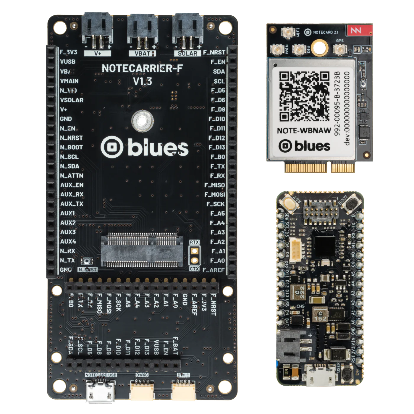
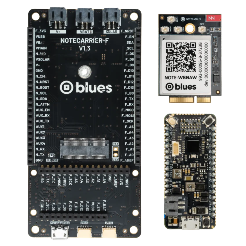
Blues Wireless, a member of the Qualcomm Advantage network, recently introduced various development kits that follow the Notecard (SoM) form factor and offer high-performance cellular connectivity options such as WiFi and LoRa. This recent development kit from Blues includes a range of components and modules designed for IoT solutions.

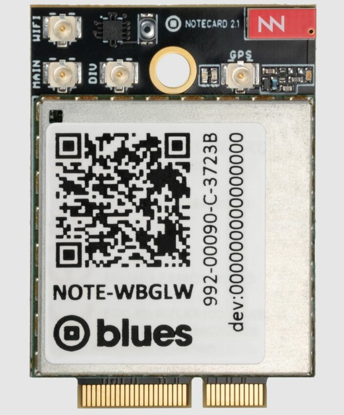
LTE CAT-1 Notecard + WiFi

The Blues’ Notecard is claimed to be the fastest and most effective way to add wireless connectivity. It is a secure feature-rich SoM that eliminates the need for regular cellular subscriptions and SIM fees, coming embedded with 10-year global connectivity and up to 500MB cellular data that is already included in the cost of the device.

Features Include:

Blues’ Notecard draws as little as approximately 8microAmp and it has the following features:

  • factory-installed ECC-384 certificate for security
  • PTCRB certification for reliability
  • efficient power management for battery operations
  • integrated GPS and accelerometer for versatile location-based applications

Notecarrier F

The Notecarrier F board is a carrier board aimed at speeding up the prototyping process. It is compatible with the LTE Cat-1 Notecard and comes with an external Nano SIM slot for carrier connectivity.
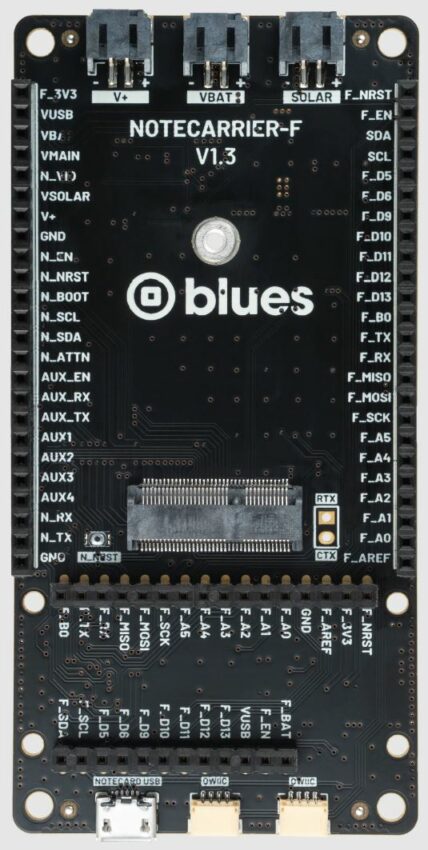
Features Include:

  • Qwiic ports for connecting I2C peripherals
  • External Nano SIM slot for carrier connectivity
  • JST PH connector for LiPo batteries
  • JST PH connector for Solar panel
  • JST PH connector for V+
  • JST SH connector for 3.3V I2C connector
  • Battery slide switch
  • MicroUSB port for power
  • Compatibility with Adafruit Feather breakout headers

Swan 3.0

The Swan 3.0 is a low-cost embeddable STM32L4R5-based microcontroller aimed at accelerating the processes of developing and deploying battery-powered IoT applications. It is best for projects with large memory requirements or extensive IO expandability, such as remote monitoring and edge inferencing. It is also designed to satisfy developers’ needs that range from early prototyping to high-volume deployment. Its novel design allows users to leverage the full range of IO capabilities that it comes with.

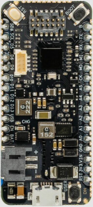
The Swan 3.0 has the following specifications:

  • Ultra-low-power Arm Cortex-M4 core operating @ up to 120MHz
  • STM32L4R5-based microcontroller
  • OS: C/C++, Arduino and CircuitPython
  • 2MB flash
  • 640KB RAM
  • 55 GPIO ports, including:
    • 8 analog and 16 digital
    • 3x SPI and 4x I2C
    • USB OTG port with full-speed capability
    • 1x 14-channel DMA
    • True Random Number Generator
    • 12-bit ADC and 2x 12-bit DAC
    • RTC and CRC calculation peripherals
  • Qwiic connector for easy integration
  • Outboard Device Firmware Update support

Conclusion

The company hopes that these latest introductions will help reduce the time it will take a typical developer to go from unboxing the product to sending custom and arbitrary data back and forth from the device to the cloud. The dev kit currently sells for $99 with an additional $15 for a programmer/debugger. The company noted that a Molex antenna with a frequency range of 698MHz ~ 3.8GHz is also included in the kit.

Other useful details such as getting started guides and datasheets can also be found on the company’s online store. There is also a video that shares more information on the development kit.

TinyM2Net is An ML Algorithm for Resource-Constrained Devices

TinyM2Net is a multimodal learning framework, designed to work with resource-constrained tiny devices like microprocessors and microcontrollers. When tested with COVID-19 audio detection and battlefield object detection, It outperformed similar recognition tools and worked well on a Raspberry Pi 4.

IoT devices are everywhere, from your smartphone smartwatch to your fridge washing macing and AC, and nowadays those are using Artificial Intelligence (AI) and Machine Learning(ML) to work better and brighter for the end users. However, running ML algorithms on resource-constrained microcontrollers and microprocessors is challenging! That is why the researchers are employing multimodality to train machine learning models. One such tool is the TinyM2Net.

In simpler terms, modality refers to how something is experienced or how we sense things, like speech, sight, or sound. Now, a multimodal machine-learning algorithm can process and relate information from multiple modalities, from medical diagnosis, security, and combat fields to robotics, vision analytics, knowledge reasoning, or navigation.

When running machine learning on tiny, resource-constrained devices, it becomes quite challenging. A typical MCU has an SRAM of less than 512kB, which makes it hard to run complex programs like deep learning on these devices. One easy solution to this problem is to process the data directly on these devices, which requires efficient multimodal learning inference with a low peak memory consumption. So researchers from the University of Maryland and the U.S. Army have introduced a new multimodal learning framework designed specifically for these resource-constrained tiny edge devices.

TinyM2Net Multimodal Learning Framework

TinyM2Net is a multimodal learning framework, designed to work with resource-constrained tiny devices like microprocessors and microcontrollers. when tested with COVID-19 audio detection and battlefield objects, It outperformed similar recognition tools and worked well on a Raspberry Pi 4.

The TinyM2Net is built upon a convolutional neural network (CNN), which had previously shown promise in classifying both audio and image data. However, traditional CNN models are very bulky and require a lot of resources to operate properly. So researchers have used various compression techniques to optimize the network architecture and as a result, the TinyM2Net was born.

In the paper “TinyM2Net: A Flexible System Algorithm Co-designed Multimodal Learning Framework for Tiny Devices ” researchers have mentioned how they used “DS-CNN” to process multimodal input like images and audio without sacrificing accuracy. The framework also uses low-precision and mixed-precision model quantization. This reduces accuracy but to compensate for that the team chose two different bit precision settings, INT4 and INT8 for the TinyM2Net framework.

Evaluating Covid & Battlefield Detection from Multimodal Data

Researchers tested the TinyM2Net framework on two different scenarios first is COVID-19 Detection using Sound and battlefield Object Detection using Sound and Images,

The COVID-19 detection model had 929 cough recordings and 893 speech recordings, and it was 90.4% accurate in identifying COVID-19 when using a standard measurement. When they tried simpler measurements, accuracy slightly dropped to 89.6% and 83.6%. However, by implementing their unique technique, they managed to raise the accuracy back to 88.4%. For comparison, the best other models that only used one type of sound (either cough or speech) were about 73% accurate.

Next, the research team wanted to detect battlefield items like helicopters, bombs, guns, and tanks using the model, so in an endeavor, they gathered 2745 images and sounds for these objects. Their model was 98.5% accurate using a standard measurement. Using simpler measurements, accuracy was 97.9% and 88.7%. In this scenario, their unique approach managed to achieve an accuracy of 97.5%. When using just one type of input (either image or sound), the accuracy was 93.6%.

The team used the TinyM2Net framework on small devices like the Raspberry Pi 4 with 2GB memory. More details are available in the research work published on Cornell University’s research-sharing platform, arXiv under open-access terms.

Solenoid, Relay, Valve Driver with Current Regulation

The project presented here is a PWM current driver for solenoids, Relays, and valves. The board will regulate the current with a well-controlled waveform to activate and reduce power dissipation at the same time. The solenoid current is ramped up fast to ensure the opening of the valve or relay. After the initial ramping, the solenoid current is kept at peak value to ensure the correct operation, after which it is reduced to a lower hold level in order to avoid thermal problems and reduce power dissipation.

The peak current duration is set at 78ms with an external capacitor C2. The current ramp peak level can be adjusted using the PR1 trimmer potentiometer in the range 83mA to 250mA, the default PWM frequency is 20KHz, PWM frequency can be changed between 20Khz to 60Khz using the external resistor R4. The enable pin has an internal pull-up, so normally chip is enabled, pulling down the enable pin brings the chip into disable mode.

JF-1564B Solenoid

Features

  • Power Supply 6V to 24V DC
  • Load Current up to 250mA
  • Peak Current Duration 78mS
  • Peak Current Adjustable range 83mA to 250mA
  • Start-Up Delay Approx 25uS
  • PWM Frequency 20Khz
  • On Board Switch to disable the output
  • Enable Pin for External Connector
  • Header Connector for Power and Solenoid
  • Fast Ramp-Up of Solenoid Current to Guarantee Activation
  • Integrated Sense Resistor for Regulating Solenoid Current
  • Solenoid Current is Reduced in Hold Mode for Lower Power and Thermal Dissipation
  • Internal Supply Voltage Regulation
  • Thermal Shutdown, Threshold 160 Degree Centigrade
  • Undervoltage Lockout (UVLO), Threshold 4.6V
  • Compact Design
  • PCB Dimensions 22.23 x 17.78mm

Connections and Other Details

  • CN1: Pin 1 Enable (High = Enable, Low = Disable) High = 4V to 7V, Pin 2 = GND
  • CN2: Pin 1 VCC 6V to 24V DC, Pin 2 = GND
  • SL1: Pin 1 = Solenoid, Pin 2 VCC (Connections for Solenoid)
  • D2: Power LED
  • SW1: Disable Switch Push to Disable

Schematic

Parts List

NO.QNTY.DESC.REF.MANUFACTURERSUPPLIER SUPPLIER PART NO
12CN1,CN22 PIN MALE HEADER PITCH 2.54MMWURTHDIGIKEY732-5315-ND
21C1100nF/50V CERAMIC SMD SIZE 0805YAGEO/MURATADIGIKEY
31C21uF/35V CERAMIC SMD SIZE 0805YAGEO/MURATADIGIKEY
41C310uF/35V CERAMIC SMD SIZE 0805YAGEO/MURATADIGIKEY
51D11N4007 SMD DIODEDIODE INCDIGIKEYS1MBDITR-ND
61D2LED RED SMD SIZE 0805OSRAMDIGIKEY475-1278-1-ND
71PR11M TRIMMER POTENTIOMETERBOURNSDIGIKEY3362P-105LF-ND
81R1DNP
91R21K 5% SMD SIZE 0805YAGEO/MURATADIGIKEY
101R33.3K 5% SMD SIZE 0805YAGEO/MURATADIGIKEY
111R4200K 1% SMD SIZE 0805YAGEO/MURATADIGIKEY
121SL12 PIN MALE HEADER PITCH 2.54MMWURTHDIGIKEY732-5315-ND
131SW1TACTILE SWITCHC&KDIGIKEYCKN9085CT-ND
141U1DRV120TIDIGIKEY296-34777-1-ND

Connections

Output Measurements

Gerber View

Photos

Video

DRV120 Datasheet

Liquid-Level Monitoring Using a Pressure Sensor – Bar-Graph Display

This project allows users to monitor the liquid level on a Bar-Graph display. The liquid level is measured using a pressure sensor, the sensor is placed on top of the tank and is connected to an open-ended tube that is submerged in the water tank. The amount of water in the tank creates a proportional amount of pressure on the sensor via the trapped air in the tube. The pressure sensor produces an equivalent output voltage. This voltage is monitored by the ADC of ATMEGA328 microcontroller and displayed on a bar-graph of 16 LEDs connected to the I/O pins of the microcontroller. The project is based on an Arduino-compatible microcontroller. Example code is written using Arduino IDE and is provided below. This project can measure water levels up to 100 cm (1m). Users may use other LED colors. Trimmer potentiometer PR1 is optional for other applications, turn full CW.

MPXV5010DP pressure sensor from NXP is used to measure the liquid level. This is an analog pressure sensor and the output of this sensor is 0.2V to 4.7V which is proportional to the applied pressure range of 0-10kPa (0 to 1.45PSI). We have used MPXV5010DP which has dual ports, but a single port sensor can also be used.

MPXV5010DP pressure sensor from NXP

Features

  • Power Supply 5V DC
  • 16 LEDs Display the Liquid Level
  • Liquid Level Measurement up to 100 cm
  • 2 x 3 mm Mounting Holes
  • PCB Dimensions 111.71 x 28.89 mm

The MPXV5010DP series piezoresistive transducers are state-of-the-art monolithic silicon pressure sensors designed for a wide range of applications, particularly those employing a microcontroller or microprocessor with A/D inputs. This transducer combines advanced micromachining techniques, thin-film metallization, and bipolar processing to provide an accurate, high-level analog output signal that is proportional to the applied pressure. The axial port has been modified to accommodate industrial-grade tubing.

Arduino Hardware

Arduino Code is available as a download and the code can be uploaded using Arduino UNO. The user will be able to display a 100cm water level, divided by 16 LEDs. The user can map analog value vs 16 LEDs as per requirement.

The Arduino-compatible board contains a few optional components, and the same hardware can be used for other applications as per user requirements.

Applications

  • Temperature Monitor
  • Humidity Monitor
  • Voltage Monitor
  • LED Light Effects
  • Gaming
  • Battery Level Monitor
  • Current Monitor
  • Tilt Monitor
  • Light Monitor

Connections and Other Details

  • CN1: Pin 1 = Sensor Input Arduino A0, Pin = GND
  • CN2: Pin 1 = VCC 5V DC, Pin 2 GND
  • LED D2 to D16 LEDs, Bar-Graph
  • D1 LED: Power LED
  • R22, R23: Sensor, Optional (Not used in this application), NTC, LDR, or any other sensor
  • SW1: No Use, Optional

Schematic


Parts List

BOMQNTYREFDESCMANUFACTURERSUPPLIER SUPPLIER PART NO
12CN1,CN22 PIN MALE HEADER PITCH 2.54MMWURTHDIGIKEY732-5315-ND
23C1,C4,C50.1uF/16V CERAMIC SMD SIZE 0805YAGEO/MURATADIGIKEY
32C2,C322PF/25V CERAMIN DISC THTYAGEO/MURATADIGIKEY
41C610uF/25V ELECTROLYTICYAGEO/MURATADIGIKEY
516D1 to D16LED GREEN 5MMKINGBRIGHTDIGIKEY754-1263-ND
61PR110 TRIMMER POTENTIOMETERBOURNSDIGIKEY3362P-103LF-ND
717R1 to R171K OR 470E 5% 1/4W THTYAGEO/MURATADIGIKEY
81R1810K 5% THT 1/4WYAGEO/MURATADIGIKEY
91R191M 5% 1/4W THTYAGEO/MURATADIGIKEY
101R201E 5% 1/4W THTYAGEO/MURATADIGIKEY
115SW1,R21,R22,R23,R24DNPDIGIKEYDO NOT INSTALL
121U1ATMEGA328 DIP28MICROCHIPDIGIKEYATMEGA328-PU-ND
131Y116MHZECS INCDIGIKEYX1103-ND
141SOCKET FOR ATMEGA32828 DIP NARROW SOCKETON SHORE TECHDIGIKEYED3050-5-ND
151D17RED LED 3MMKINGBRIGHTDIGIKEY754-1895-ND

Connections

Gerber View

Photos

Video

MPXV5010DP Datasheet

Hi-Efficient 20W Mono Class-D Audio Amplifier

This is a Hi-Efficient 20W mono Class-D audio amplifier, designed to drive speakers as low as 4 ohms in a bridge-tied-load configuration. Due to the low power dissipation and high efficiency of up to 90%, the module doesn’t require a heatsink. The project is built using PAM8320 chip which features short circuit protection, thermal shutdown, over-voltage protection and under-voltage lock-out. Ferrite-Bead is provided on the output of the speaker connection to eliminate EMI. Connect SD to a high and MUTE to a low for normal operation.

Features

  • Operates from 4.5V to 15V
  • 20W into 4Ω BTL Load from 12V Supply
  • Single-Ended Analog Input
  • No Pop Noise for Start-up and Shut-down Sequences
  • Output Power at 1% THD+N (1Khz) @ 15W Output
  • Internal Oscillator (No External Components Required)
  • Highly Efficient Class-D Operation Eliminates Need for Heat Sinks
  • Thermal and Short-Circuit Protection with Auto Recovery
  • Over Voltage Protection and Under Voltage Lock-out
  • Screw Terminal for Speak and Power Connections
  • On Board Trimmer Potentiometer for Volume Control
  • On Board Jumpers for Shutdown and Mute Functions
  • On Board Power LED
  • Header Connector for Audio Input
  • PCB Dimensions 39.53 x 33.97 mm
  • 2 x 3 mm PCB Mounting Holes

Shutdown Operation

The PAM8320 employs a shutdown operation mode to reduce supply current to the absolute minimum level during periods of non-use to save power. The SDN input terminal should be pull high during normal operation. Pulling SDN low causes the outputs to be muted and the amplifier enters a low-current state. SDN should never be left unconnected.

Anti-POP and Anti-Click Circuitry

The PAM8320 contains circuitry to minimize turn-on and turn-off transients or “click and pops”, where turn-on refers to either power supply turn-on or device recover from shutdown mode. When the device is turned on, the amplifiers are internally muted. An internal current source ramps up the internal reference voltage. The device will remain in mute mode until the reference voltage reaches half supply voltage. As soon as the reference voltage is stable, the device will begin full operation. For the best power-off pop performance, the amplifier should be set in shutdown mode prior to removing the power supply voltage.

Short-circuit Protection

The PAM8320 has short circuit protection circuitry on the outputs to prevent damage to the device when output-to-output shorts (BTL mode), output-to-GND shorts, or output-to-VCC shorts occur. Once a short-circuit is detected on the outputs, the output drive is immediately disabled.  This is not a latched fault, if the short is removed the normal operation is restored.

Thermal Protection

Thermal protection prevents the device from damage. When the internal die temperature exceeds a typical of 160°C the device will enter a shutdown state and the outputs are disabled. This is not a latched fault, once the thermal fault is cleared and the temperature of the die decreased by 40°C the device will restart with no external system interaction.

Over Voltage Protection and Under Voltage Lock-out (OVP and UVLO)

An over-voltage protection (OVP) circuit is integrated in PAM8320, when the supply voltage is over 18V the OVP is active and then the output stage is disabled. The PAM8320 will auto recovery when the supply voltage is lower than the OVP threshold. The PAM8320 incorporates circuitry designed to detect low supply voltage. When the supply voltage drops to 4.4V or below, the PAM8320 goes into a state of shutdown. When the supply voltage is higher than 4.5V normal operation is resumed.

Connections and other details

  • CN1 Power Supply: Pin 1 = VCC, Pin 2 = GND
  • CN2 Audio Input: Pin 1 Audio Input, Pin 2 = GND
  • CN3 Speaker: Pin 1 = Speaker 1, Pin 2 Speaker 2
  • CN4 Mute and Shutdown: Pin 1 = VCC, Pin 2 Shutdown, Pin 3 = Mute, Pin 4 = GND
  • D1: Power LED
  • PR1: Volume Control

Schematic

Parts List

NOQNTY.REFDESCMANUFACTURERSUPPLIERSUPPLIER PART NO
11CN12 PIN SCREW TERMINAL PITCH 5.08MMPHOENIXDIGIKEY277-1247-ND
21CN22 PIN MALE HEADER PITCH 2.54MMWURTHDIGIKEY732-5315-ND
31CN32 PIN SCREW TERMINAL PITCH 5.08MMPHOENIXDIGIKEY277-1247-ND
41CN44 PIN MALE HEADER PITCH 2.54MMWURTHDIGIKEY732-5317-ND
53C1,C8,C13100nF/50V CERAMIC SMD SIZE 0805YAGEO/MURATADIGIKEY
63C2,C9,C1410uF/25V CERMIC SMD SIZE 1210YAGEO/MURATADIGIKEY
72C3,C15470uF/25V ELECTROLYTICNICHICONDIGIKEY493-2194-1-ND
81C40.47uF/25V CERAMIC SMD SIZE 0804YAGEO/MURATADIGIKEY
94C5,C7,C10,C111uF/25V CERAMIC SMD SIZE 0805YAGEO/MURATADIGIKEY
102C6,C121nF/25V CERMAIC SMD SIZE 0805YAGEO/MURATADIGIKEY
111D1RED LED SMD SIZE 0805OSRAMDIGIKEY475-1278-1-ND
122L1,L2FERRITE-BEAD 600-OHMS SMD SIZE 1206 LAIRDDIGIKEY240-2405-1-ND
131PR110K TRIMMER POTENTIOMETERPIHERDIGIKEYPT10LV10-103A2020-S
142R1,R20E SMD SIZE 0805YAGEO/MURATADIGIKEY
151R310E 5% SMD SIZE 1206YAGEO/MURATADIGIKEY
161R41K 5% SMD SIZE 0805YAGEO/MURATADIGIKEY
171U1PAM8320 SOICDIODE INCDIGIKEYPAM8320RDRDICT-ND

Connections

Gerber View

Photos


Video

PAM8320 Datasheet

8 Channel ESP32 Remote Control

This is an 8-channel remote in a compact board suitable for remote ON/OFF applications using Bluetooth or Wi-Fi protocol. The board consists of an ESP32 module and 8 tactile switches connected to various GPIO. The circuit works with 3.3VDC power supply and a Li-Ion battery can be used to power the board. The onboard LED indicates the power. There is an onboard programming connector that helps users program the ESP32 module using Arduino IDE. The users have to write their own code to use the module, according to their requirements.

More information about ESP32 Module and Programming: https://randomnerdtutorials.com/getting-started-with-esp32/

Features

  • Power 3.3V DC
  • On Board Programming Connector for ESP32
  • On Board 8 Tactile Switches
  • 2 x 3 mm Mounting Holes
  • PCB Dimensions 80.65 x 33.66 mm

Connections and Other Details

  • CN1 Programming and Power Input: Pin 1 = 3.3V DC, Pin 2 = GND, Pin 3 = TX, Pin 4 = RX, Pin 5 = GPIO0, Pin 6 = Enable
  • SW1:GPIO15, SW2:GPIO16, SW3:GPIO17, SW4:GPIO18, SW5:GPIO19, SW6:GPIO21, SW7:GPIO22, SW8:GPIO23
  • D1: Power LED

Schematic

Parts List

NO.QNTY.REF.DESCMANUFACTURERSUPPLIERSUPPLIER PART NO
11CN16 PIN MALE HEADER PITCH 2.54MMWURTHDIGIKEY732-5319-ND
22C1,C2100nF/25V CERAMIC SMD SIZE 0805YAGEO/MURATADIGIKEY
31C310uF/10V CERAMIC SMD SIZE 0805YAGEO/MURATADIGIKEY
41D1LED-RED SMD SIZE 0805OSRAMDIGIKEY475-1278-1-ND
51R110K 5% SMD SIZE 0805YAGEO/MURATADIGIKEY
61R21K 5% SMD SIZE 0805YAGEO/MURATADIGIKEY
78SW1-SW8TACTILE SWITCHNKK SWITCHDIGIKEYHP0215AFKP2-ND
81U1ESP32-WROOM-MODULEESPDIGIKEYALIEXPRESS/EBAY

Connections

Gerber View

Photos

ESP32 Datasheet

16 Channel RC Servo Driver with I2C Interface

This is a 16-channel servo driver that can drive 16 x RC servos over I2C interface. The project is built using PCA9685 chip, a 16-channel PWM generator that can drive 16-channel servos simultaneously. The board can be connected to Arduino or another microcontroller. Driving robots, and animatronics puppets is easy with this board. The board works with 5VDC and a separate power supply connector is provided to power the RC servo with 6VDC. 6 x address Solder jumper is provided to set the board address, and this helps users to wire up 62 board on a single I2C line and drive up to 992 servos. The board also can be used for other applications that require 16-channel PWM signals. The frequency can be adjusted between 24 Hz to 1526 Hz and the duty cycle ranges from 0 to 100%.

It is important to use a high current power supply that should be able to power the total load of 16 servos and use a C4 = 1000uF/10V capacitor. You can also download the Arduino code to test the board. The test is done with Arduino UNO. The following Arduino pins are used to perform the test, refer to the connection diagram for the connection between Arduino Uno and the PWM board.

Arduino Uno Connections

Features

  • Power Supply RC Servo 6V DC (VDD)
  • Power Supply Chip/Logic 5V DC (VCC)
  • 3 Pin x 16 Header Connector for 16 RC Servo
  • Screw Terminals for RC Servo (6V DC) RC Servo Power Supply
  • 5 Pin Header Connector for I2C Interface and VCC Power
  • On Board Power LED
  • 6 Solder Jumper to Set the I2C Address
  • 66 Board can run over a single I2C Bus which can output 992 Channels
  • Adjustable Frequency 24 Hz to 1526 Hz
  • Adjustable Duty Cycle 0 to 100%
  • Configurable Push-pull or Open-drain Output
  • Output Enable Pin to Disable All the Outputs
  • 4 x 3mm Mounting Holes
  • PCB Dimensions 44.13 x 34.45mm

Applications

  • Animatronics
  • Puppetry
  • Multi-Servo Based Robots
  • Hexapod Robot
  • Servo-Based Robotics Arm
  • Automation

Connections and Other Details

  • Jumper J1 = Address A0
  • Jumper J1 = Address A1
  • Jumper J1 = Address A2
  • Jumper J1 = Address A3
  • Jumper J1 = Address A4
  • Jumper J1 = Address A5
  • CN1 1 x16Pin = PWM 0-15
  • CN2 1x16Pin = VDD=6V
  • CN3 1x16Pin = GND
  • CN4: Pin 1 VCC(5VDC), Pin 2 = SDA, Pin 3 = SCL, Pin 4 = OE(Enable), Pin 5 = GND
  • CN5: Pin 1 VDD(6VDC) for Servo, Pin 2 GND
  • D1 Power LED

Schematic

Parts List

NOQNTYREFDESCMANUFACTURERSUPPLIERSUPPLIER PART NO
13CN1,CN2,CN316 PIN MALE HEADER PITCH 2.54MMWURTHDIGIKEY732-5327-ND
21CN45 PIN MALE HEADER PITCH 2.54MMWURTHDIGIKEY732-5318-ND
31CN52 PIN SCREW TERMINAL PITCH 5.08MMPHOENIXDIGIKEY277-1247-ND
41C110uF/10V CERAMIC SMD SIZE 0805YAGEO/MURATADIGIKEY
52C2,C3100nF/25V CERAMIC SMD SIZE 0805YAGEO/MURATADIGIKEY
61C41000uF/10V ELECTROLYTICPANASONICDIGIKEYPCE3868CT-ND
71D1LEDOSRAMDIGIKEY475-1278-1-ND
82D2,D3DNP
96J1,J2,J3,J4,J5,J6JUMPERSOLDER JUMPER
101R11K 5% SMD SIZE 0805YAGEO/MURATADIGIKEY
119R2,R3,R4,R5,R6,R7,R8,R9,R1010K 5% SMD SIZE 0805YAGEO/MURATADIGIKEY
1216R11 TO R26220E 5% SMD SIZE 0805YAGEO/MURATADIGIKEY
131U1PCA9685DWNXPDIGIKEY568-11925-1-ND

Connections

Gerber View

Photos

Videos

PCA9685 Datasheet

2 Channel Wi-Fi Relay Module Using ESP8266 NodeMCU

The project described here is an ESP8266 NodeMCU Two Channel Relay Module. This board enables users to control 2 x relays remotely. The 2 channels can be controlled remotely using a webserver/WiFi connection. The project works with 5VDC. Two LEDs indicate relay operation. Screw terminals help user to connect devices and power the supply. Relay output has 3 contacts normally closed, normally open, and common. Relay can drive a load up to 10A/250VAC or 10A/30VDC. It can be used in applications such as IoT and smart Home/Home automation.

The board can be connected to a server through a TCP Client and also can be controlled by HTTP. With this module, users can upload firmware and can create a versatile IoT project. It is suitable for your smart home and IoT project with network control.

More details about the software and code are available here:

Hardware Details

  • ESP8266 MCUNODE (WiFi)
  • 2 x 5V Relay
  • 2 x LEDs Relay Operations
  • 2 x 3 Pin Screw Terminals (Relay Output Normally Open, Normally Closed and Common Connections)
  • 2 Pin Screw Terminal Power Input 5V DC
  • 2 x BJT (Transistors) drive relays
  • 2 x Flyback diodes
  • ESP8266 GPIO15 Connected to Relay 1
  • ESP8266 GPIO13 Connected to Relay 2

Features

  • Power Supply 5V DC
  • Current 100mA (when Relays are on)
  • 2 x Relay LED
  • 4 x 3MM Mounting Holes
  • Screw Terminal for Easy Connections
  • PCB Dimensions 57.63 x 53.98 mm

Connections and Other Details

  • CN1 Power Supply: Pin 1 = 5V DC, Pin 2 = GND
  • CN2: Pin 1 Normally Closed, Pin 2 = Common, Pin 3 = Normally Open (Relay 1 Contacts)
  • CN3: Pin 1 Normally Closed, Pin 2 = Common, Pin 3 = Normally Open (Relay 2 Contacts)
  • D2: LED for Relay 1
  • D4: LED for Relay 2

Schematic

Parts List

NOQNTYREFDESCMANUFACTURERSUPPLIERSUPPLIER PART NO
11CN12 PIN SCREW TERMINAL PITCH 5.08MMPHOENIXDIGIKEY277-1247-ND
22CN2,CN33 PIN SCREW TERMINAL PITCH 5.08MMPHOENIXDIGIKEY277-1248-ND
31C110uF/10V CERAMIC SMD SIZE 0805YAGEO/MURATADIGIKEY
41C2100nF/50V CERAMIC SMD SIZE 0805YAGEO/MURATADIGIKEY
52D1,D3SM4007 SMDDIODE INCDIGIKEYS1MBDITR-ND
62D2,D4LED RED SMD SIZE 0805OSRAMDIGIKEY475-1278-1-ND
72Q1,Q2BC847NEXPERIADIGIKEY1727-2924-2-ND
82RE1,RE25V RELAYAMERICAN/ZETTLERDIGIKEY3385-AZ943-1CH-5DE-ND
91R11K 5% SMD SIZE 0805YAGEO/MURATADIGIKEY
102R2,R32K2 5% SMD SIZE 0805YAGEO/MURATADIGIKEY
111U1ESP8266NODEMCU MODULEEBAY/ALIEXPRESSDIGIKEYEBAY/ALIEXPRESS

Connections

Gerber View

Photos

ESP8266 NodeMCU Datasheet

3 Phase Brushless Motor Driver using L6235

The project presented here is a 3-phase Brushless motor driver. The project consists of an L6235 device which is DMOS fully integrated 3-phase motor driver with overcurrent protection. Manufactured in BCD technology, the device combines isolated DMOS power transistors with CMOS and bipolar circuits on the same chip. The device includes all the circuitry needed to drive a 3-phase BLDC motor including a 3-phase DMOS bridge, a constant off-time PWM current controller, and the decoding logic for single-ended hall sensors that generates the required sequence for the power stage. Running the project in stand-alone mode, instead, three control pins enable the device, setting the direction of the rotation, breaking the motor, and the jumper chooses to run in torque or speed mode. The board is suitable for small motors used in many home appliances and can handle torque and speed control with a high efficiency of up to 95%.

Operation

  • CN4: Pin2 High/Low to select the Direction of the Motor
  • CN4: Pin 3 Enable, High=Enable, Low = Disable
  • CN4: Pin 4 Brake, High=Normal Operation, Low=Brake
  • J1: Jumper Speed Mode or Torque Mode Selection
  • PR1: Adjust the Speed

Features

  • Operating supply voltage from 8 to 48 V
  • Load Current Up to 2.8A, Peak Current 5.6Amp
  • Non-dissipative overcurrent detection and protection
  • Diagnostic output
  • Constant tOFF PWM current controller
  • Slow decay synchr. rectification
  • 60° and 120° hall effect decoding logic
  • Brake function
  • Cross conduction protection
  • Thermal shutdown
  • Undervoltage lockout
  • Integrated fast freewheeling diodes (Chip)
  • 4 x 3mm Mounting Holes
  • PCB Dimensions 59.69 x 49.53mm

Current Ratings

Load current rated for a maximum of 2.8ARMS. and 5.6Apeak. The device has a built-in Over-Current Detection (OCD) that allows protection against short circuits between the outputs and between the output and ground.

Voltage Ratings and Operation Range

The L6235 requires a single supply voltage (VS), for the motor supply. The operating range for VS is 8 to 48 V. To prevent working into undesirable low supply voltage an Under Voltage Lock Out (UVLO) circuit shuts down the device when the supply voltage falls below 6 V; to resume normal operating conditions, VS must then exceed 7 V. The hysteresis is provided to avoid false intervention of the UVLO function during fast VS ringing’s. It should be noted, however, that DMOS’s RDS(ON) is a function of the VS supply voltage. Actually, when VS is less than 10V, RDS(ON) is adversely affected, and this is particularly true for the High Side DMOS that are driven from VBOOT supply. This supply is obtained through a charge pump from the internal 10V supply, which will tend to reduce its output voltage when VS goes below 10V.

Brake

In general, motor braking can be achieved by making a short circuit across the windings: the BEMF forces a current, proportional to the braking torque, that flows in the opposite direction than in normal running mode. For high BEMF and inertia moment, the current may reach very high values: a power resistor is often used to reduce the maximum braking current and dissipate the motor energy. L6235 Brake pin can be used to quickly stop the motor while it is running: providing a low logic level to this pin all the high-side DMOS switch on, making a short-circuit across the motor windings.  A power resistor is not used: while the motor is braking, both Thermal and Over-Current protections still work, avoiding BEMF from causing a current exceeding the device’s maximum ratings.

Connections and Other Details

  • CN1: Pin 1 = VDD 8 to 48V DC Motor Power, Pin 2 = GND
  • CN2: Pin 1 = Motor 1, Pin 2 = Motor 2, Pin 3 = Motor 3
  • CN3: Pin 1 VCC 5V DC, Pin 2 = Hall Sensor 1, Pin 3 = Hall Sensor 2, Pin 4 = Hall Sensor 3
  • CN4: Pin 1 = VCC, Pin 2 = Direction, Pin 3 = Enable, Pin 4 = Brake, Pin 5 = GND, Pin 6 = Ref No Use, Pin 7 = NC, Pin 8 = VDD 8 to 48V
  • PR1: Speed Control
  • J1: Jumper for Speed Control or Torque Control Selection
  • J2: Jumper for Brake
  • J3: Jumper for Enable
  • J4: Jumper for Direction
  • D2: Motor Power LED

Schematic

Parts List

NO.QNTY.REF.DESC.MANUFACTURERSUPPLIERSUPPLIER PART NO
11CN12 PIN SCREW TERMINAL PITCH 5.08MMPHOENIXDIGIKEY277-1247-ND
21CN23 PIN SCREW TERMINAL PITCH 5.08MMPHOENIXDIGIKEY277-1248-ND
31CN35 PIN MALE HEADER PITCH 2.54MMWURTHDIGIKEY732-5318-ND
41CN48 PIN MALE HEADER PITCH 2.54MMWURTHDIGIKEY732-5321-ND
53C1,C3,C50.1uF/50V CERAMIC SMD SIZE 0805YAGEO/MURATADIGIKEY
61C2220uF/50V ELECTROLYTIC THTPANASONICDIGIKEYP10398TB-ND
72C8220nF/50V CERAMIC SMD SIZE 0805YAGEO/MURATADIGIKEY
82C6,C1010KPF/50V CERAMIC SMD SIZE 0805YAGEO/MURATADIGIKEY
91C733nF/50V CERAMIC SMD SIZE 0805YAGEO/MURATADIGIKEY
101C91KPF/50V CERAMIC SMD SIZE 0805YAGEO/MURATADIGIKEY
112D1,D31N4148MICROCHIPDIGIKEY1N4148UR-1-ND
121D2LED RED SMD SIZE 0805OSRAMDIGIKEY475-1278-1-ND
131C4220nF/50V CERAMIC SMD SIZE 1206YAGEO/MURATADIGIKEY
144J1,J2,J3,J43 PIN MALE HEADER PITCH 2.54MMWURTHDIGIKEY732-5316-ND
151PR15K TRIMMER POTENTIOMETERBOURNSDIGIKEY3362P-502LF-ND
161R120K 1% SMD SIZE 0805YAGEO/MURATADIGIKEY
172R2,R54.7K 5% SMD SIZE 0805YAGEO/MURATADIGIKEY
181R32.2K 5% SMD SIZE 0805YAGEO/MURATADIGIKEY
191R4100E 5% SMD SIZE 0805YAGEO/MURATADIGIKEY
204R6,R14,R16,R181K 5% SMD SIZE 0805YAGEO/MURATADIGIKEY
211R75.6K 5% SMD SIZE 0805YAGEO/MURATADIGIKEY
221R81.8K 5% SMD SIZE 0805YAGEO/MURATADIGIKEY
233R9,R10,R1110K 5% SMD SIZE 0805YAGEO/MURATADIGIKEY
241R121M 5% SMD SIZE 0805YAGEO/MURATADIGIKEY
253R13,R15,R171E 1% SMD SIZE 1206YAGEO/MURATADIGIKEY
261R1933K 5% SMD SIZE 0805YAGEO/MURATADIGIKEY
271R2047K 5% SMD SIZE 0805YAGEO/MURATADIGIKEY
281U1LM358 SOIC8TIDIGIKEY296-14601-1-ND
291U2L6235STDIGIKEY497-4010-1-ND
304SHUNTSHUNT FOR JUMPERSSULLINS CONECTDIGIKEYS9001-ND

Connections

Gerber View

Photos

Video

L6235 Datasheet

DC Motor Control Using Joystick

This is a compact, low-profile, and high-performance DC motor driver that provides easy control of a DC motor using a joystick. This small-size board can drive small to medium-sized brushed DC motors with up to 2.5A continuous and 6A peak currents. It is an Arduino-compatible project that helps users develop their own code and drive DC brushed motor as per application requirements. The Arduino-compatible hardware consists of an ATMEGA328 microcontroller and IFX9201 H-Bridge chip.

Arduino Code

Arduino example code is available and the user will be able to drive a DC brushed motor up to 2.5A using a joystick. Follow the link below to learn more about programming the new ATMEGA328 chip using Arduino IDE.


Applications

  • Camera Pan Tilt Head
  • Linear/Rotary Actuator
  • Camera Slider
  • Robotics
  • Motorized Curtains
  • Lifting Equipment
  • Medical equipment/Furniture
  • Camera Focus/Zoom Motor

Features

  • Power Supply for the Load 8V to 30V DC (Max 36V)
  • Motor Lead up to 2.5A Peak 6Amps
  • Over Current Shutdown Threshold 8Amps
  • Logic Supply 5.0 V
  • No Heatsink Required
  • PWM Frequency 975Hz
  • On Board Power LED
  • Screw Terminals for Motor and Power Supply Connections
  • PCB Dimensions 57.47 x 37.15 mm

Various other possible applications with this hardware

  • Motor Speed Control Using Potentiometer
  • Motor Control with Limit Switch, a Limit switch can be connected to D7 and D8 Pin of Connector CN5
  • Motor Velocity Control using Encoder, the encoder can be connected to D7/D8 of CN5

Selecting a DC motor

The project can drive small DC motors with peak currents of up to 6 A. The achievable continuous drive current is lower and depends on supply voltage, switching frequency, and cooling conditions. Realistic continuous drive currents for this project are in the range of 1 A to 2.5 A. Many motors for toys, RC models, or robotics fall in this range.

Arduino Pin

  • Arduino D5 = PWM Pin of IFX9201 H-Bridge
  • Arduino D6 = Direction Pin of IFX9201 H-Bridge
  • Arduino D4 = Disable Pin of IFX9201 H-Bridge (High = Disable, Low = Enable)
  • Arduino D5 = PWM IFX9201 H-Bridge

The project is built using an IFX9201 H-Bridge chip, more info about similar can be found here

Protection and Diagnostics – Both output stages of the IFX9201SG are equipped with fault diagnostic functions:

  • Short-to-supply voltage (SCVS)
  • Short to ground (SCG)
  • Open load (OL)
  • Over-temperature (OT)

Connections and Other Details

  • CN1: Optional No Use
  • CN2: Power Supply for Motor Pin 1 = VDD 8 to 30V DC, Pin 2 = GND
  • CN3: Motor Connections, Pin 1 = Motor, Pin 2 = Motor
  • CN4: Arduino Programming/Bootloader Connector, Pin 1 = RX, Pin 2 = TX, Pin 3 = Reset, Pin 4 GND, Pin 5 = VCC, Pin 6 = D11, Pin 7 = D12, Pin 8 = 13
  • CN4: Optional Limit Switch, Pin 1 = VCC, Pin 2 = Arduino D7, Pin 3 = Arduino D8, Pin 4 = GND
  • U2: Joystick, Pin 1 VCC, Pin 2 = Analog A1, Pin 3 = GND
  • D1: Power LED for Motor Supply

Schematic


Parts List

NOQNTY.REFDESC.MANUFACTURERSUPPLIERSUPPLIER PART NO
13CN1,CN6,C10DNPDO NOT INSTALL
21CN22 PIN SCREW TERMINAL PITCH 5.08MMPHOENIXDIGIKEY277-1247-ND
31CN32 PIN SCREW TERMINAL PITCH 5.08MMPHOENIXDIGIKEY277-1247-ND
41CN48 PIN MALE HEADER PITCH 2.54MMWURTHDIGIKEY732-5321-ND
51CN54 PIN MALE HEADER PITCH 2.54MMWURTHDIGIKEY732-5317-ND
62C1,C310uF/35V CERAMIC SMD SIZE 0805YAGEO/MURATADIGIKEY
74C2,C4,C5,C6100nF/50V CERAMIC SMD SIZE 0805YAGEO/MURATADIGIKEY
81C7100uF/35V ELECTROLYTICRUBYCONDIGIKEY1189-1620-1-ND
92C8,C910nF/50V CERAMIC SMD SIZE 0805YAGEO/MURATADIGIKEY
102C11,C1222PF/50V CERAMIC SMD SIZE 0805YAGEO/MURATADIGIKEY
111D1LED RED SMD SIZE 0805OSRAMDIGIKEY475-1278-1-ND
123R1,R3,R410K 5% SMD SIZE 0805YAGEO/MURATADIGIKEY
131R24.7K 5% SMD SIZE 0805YAGEO/MURATADIGIKEY
141R50E SMD SIZE 0805YAGEO/MURATADIGIKEY
151R61M 5% SMD SIZE 0805YAGEO/MURATADIGIKEY
161U1IFX9201INFINIONDIGIKEYIFX9201SGAUMA1CT-ND
171U2ATMEGA328TQPF-32MICROCHIPDIGIKEYATMEGA328PB-AURCT-ND
181U33 PIN MALE HEADER PITCH 2.54MMWURTHDIGIKEY732-5316-ND
191X116MhzECS INCDIGIKEYX1103-ND

Connections

Gerber View

Photos

Video

IFX9201 Datasheet

TOP PCB Companies