In one of our previous articles, we built a DIY air quality monitor which was based on measuring the amount of Hydrocarbon concentration in the air using the BME680 VOC Whisker. While things work quite well using that method, there are several other parameters and air constituents which also have the same devastating effect and may be present in the air, but not detected by the sensor used in our previous project. One of such easy to overlook, constituents of air is Particulate Matter, and for today’s tutorial, we will build a device to measure its concentration in air.
Particulate matter is the sum of all solid and liquid particles (many of which are hazardous) suspended in the air. It is a complex mixture of organic and inorganic particles, such as dust, pollen, soot, smoke, and liquid droplets. These particles are created mostly when fuel is burnt and when the dust is carried by the wind. They vary greatly in origin, composition, and size which is the most popular way of categorizing them with the PM10 and PM2.5 classification.
Portable Fine Dust PM10 Analyzer with Large OLED Digits – [Link]
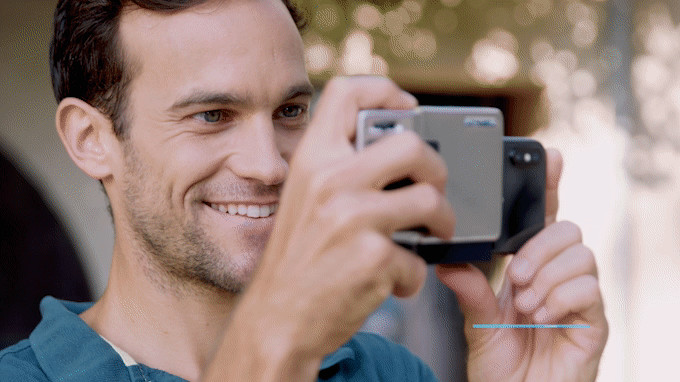
Mobile photography is fast growing beyond a hobby or a way for people to capture important moments. Thanks to the week-on-week breakthroughs and improvements being made on the camera by the phone manufacturers, it is now becoming a mainstream method of documenting visual information, with both professionals (from Journalists to Magazine Photographers) and Semi-professionals (like YouTubers and Instagram influencers) relying on it as a way to create their video or picture contents. However, phones are made for the mass public, and thus lack some of the important features that standard professional camera’s come with, for quality video and pictures. Solving this and providing Smartphone users with the same controls, feel, and handling that comes with a professional camera was what led to the development of the Pictar Pro.
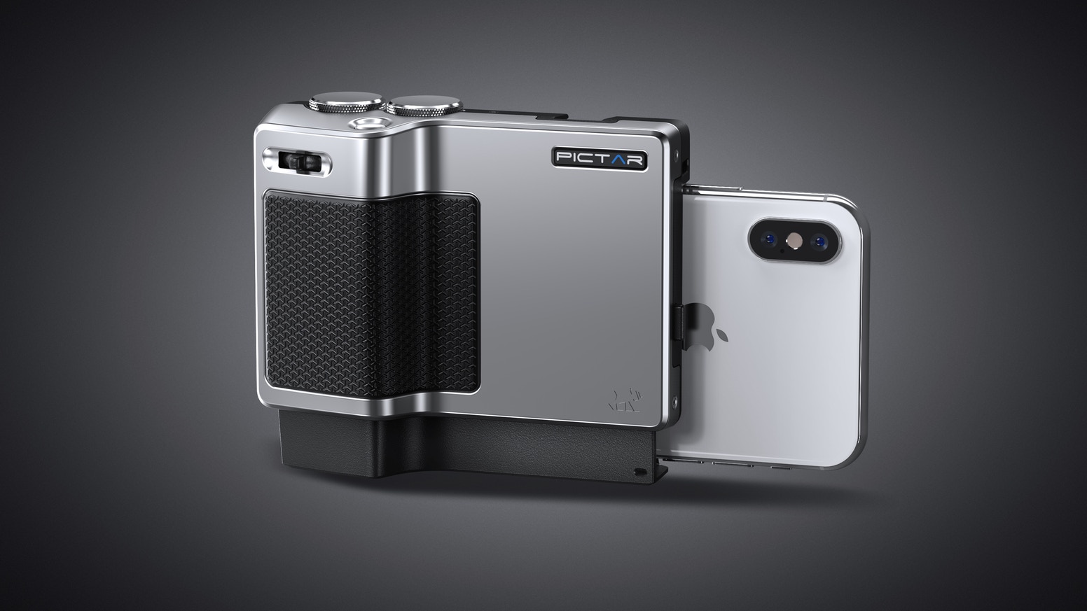
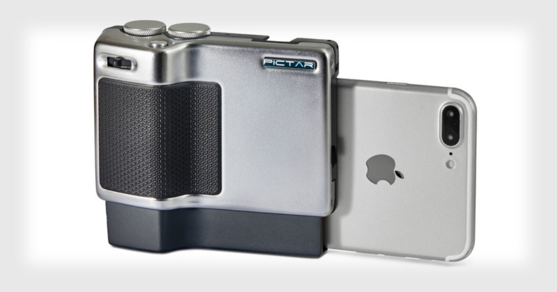
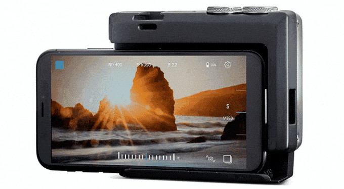
The Pictar Pro is a combined hardware and software (Mobile App) solution for smartphone photography. The Pictar Pro hardware is a smartphone attachment that enables users to add dozens of controls and features to the smartphone, bridging the gap between the Phone’s power and the usability of a professional camera. The hardware also provides a terrific user experience with a polished metal grip and an unmatched front-loaded intuitive user interface.
Pictar Pro
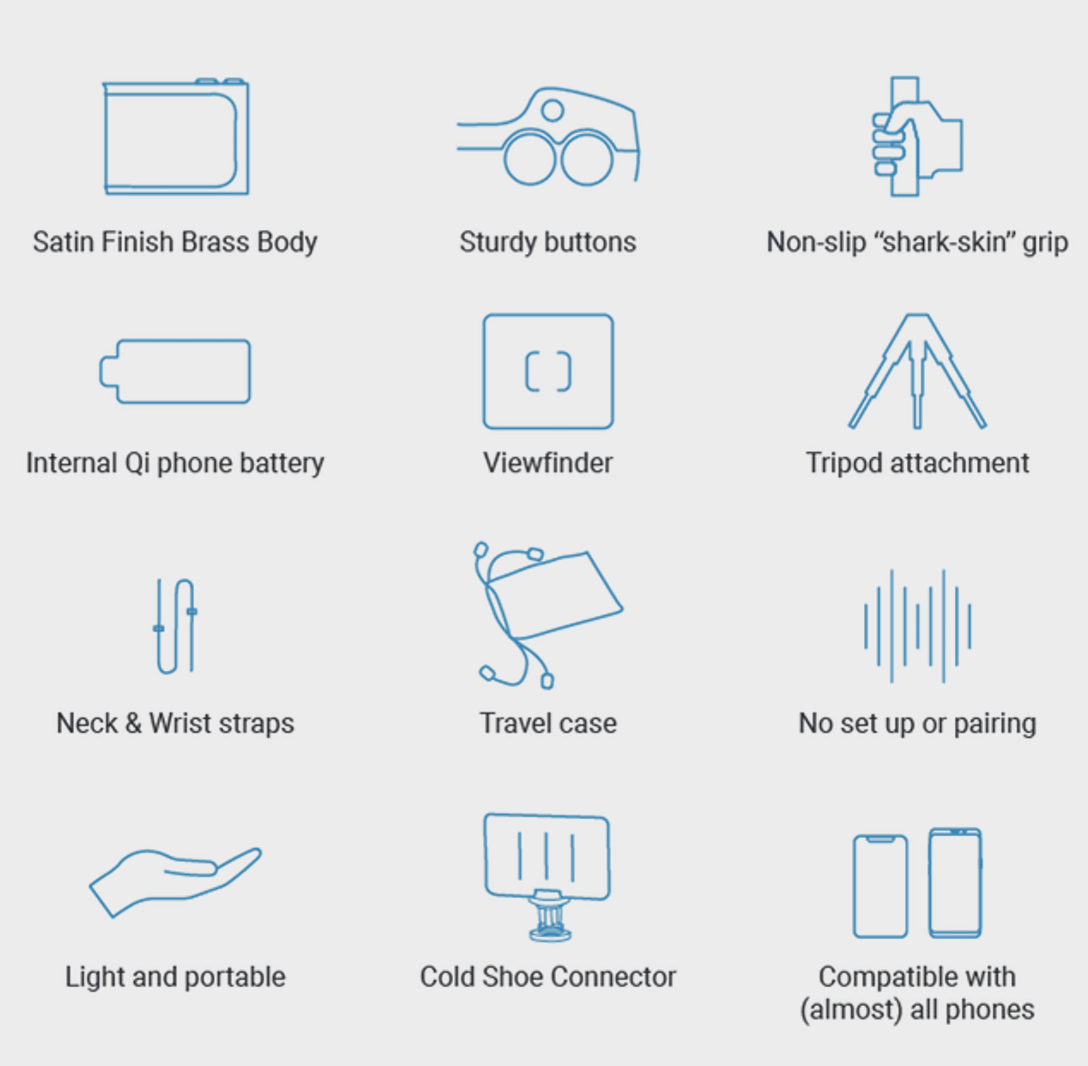
Some of the features of the hardware are highlighted in the image below;
Pictar Pro Features
Utilizing a seamless modern pairing connection technology, Pictar Pro pairs with your smartphone instantly via sound-waves, and becomes accessible by the Pictar Pro app with no physical or Bluetooth connection necessary.
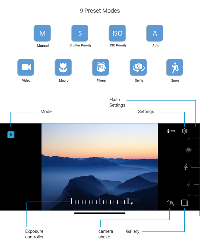
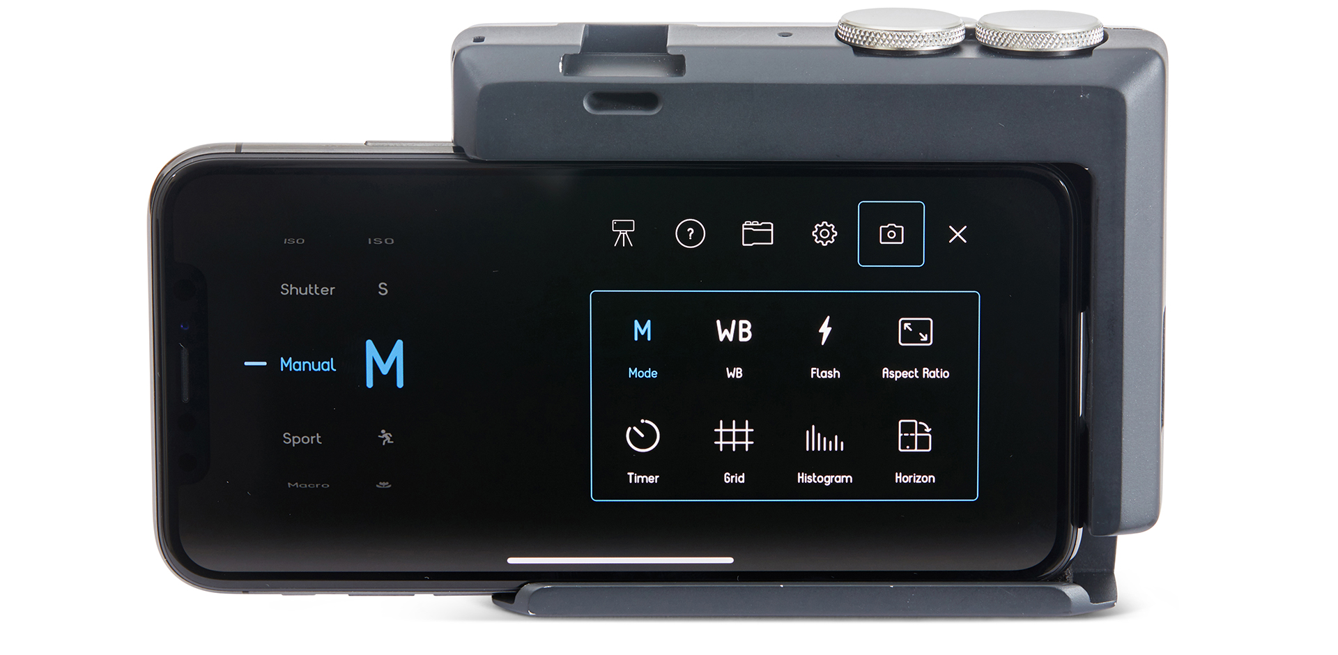
The Pictar Pro Software (Mobile App) comes with several photography features to provide users with more control, information, and options on the output of each shot. The software allows users to select between 9 different preset modes.
Pictar Pro App
It also comes with additional features like white balance control and manual focus which gives users the ability to select which objects come into focus and which ones fall out of focus. The app also adds DSLR features like Horizon Indicator which shows when your shot is leveled and a histogram feature which helps review the lighting details behind the shot.
Some of the other features of the Pictar Pro include;
Advanced digital zoom
Manual ISO
White Balance Control
Shutter Speed Control
Adjust Frame Rate
Video Stabilization
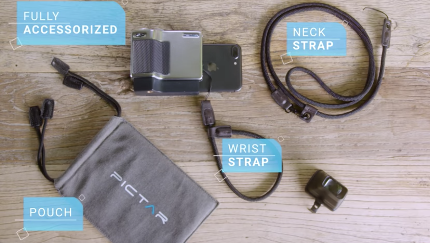
The Pictar Pro comes with several accessories to enhance the experience of users. It comes with;
A travel case which ensures the device is safe when moving it around.
Pictar Pro Viewfinder which is an unfold and pop 0n-screen for dark and focussed preview
Pictar Pro Wrist Wrap which allows users hold the device safely in hand.
Pictar Pro Neck Wrap. The neck wrap allows users to wear the smartphone around the neck, just like you will do a professional camera
Miggo Splat Flexible Tripod which comes in handy for users who need to shoot with the Pictar Pro on a standard.
Pictar Pro Accessories
When attached to Pictar Pro’s body, the foldable silicon viewfinder enables you to preview images and videos in full vivid detail- even under the brightest lights. Like when you’re outdoors on a sunny afternoon.
Migg0 concluded the fundraiser for the Pictar Pro on IndieGoGo a while back with the deliveries currently being made to backers, but the last chance perk was created recently to allow new backers on board with delivery prepped for January 2020. For the new perk, the Pictar Pro kit reward comes with a $169 price tag while the Pictar Pro + kit goes for $189.
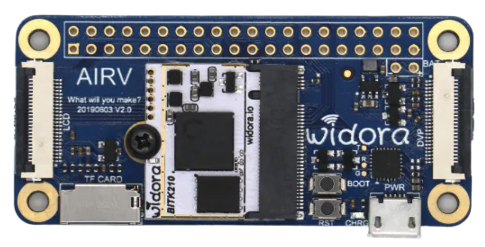
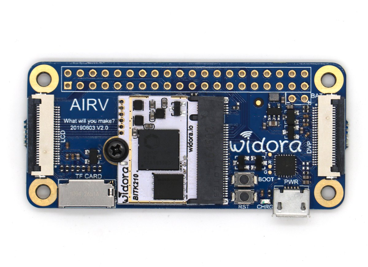
Widora, who has been one of the companies championing the development of open-source boards for IoT applications, with boards like the Widora AIR and the Widora Neo, recently announced the planned launch of a new board; a RISC-V binocular facial recognition development board which according to the company’s post will be the smallest binocular facial recognition module yet.
Widora AIRV2
Based on the tweet which was posted a few weeks back, the board which will be called the FaceR will be based on the same BITK210 module on which the Widora AIRV2 board is based. The company tweeted
“We “built” the smallest #K210 module, Also based on it made the #AIRV2 board, it is undoubtedly very beautiful, but also the king of cost-effective. Now, Starting today, we will introduce the current smallest volume binocular live face recognition module #faceR by the end of 2019″.
The tweet didn’t include any image or details of the new board, carrying the picture of the AIRV2 development board instead but it is safe to assume that the board might be designed with the same physical layout and maybe form factor as the AIRV2, with the GPIO header to the top, the K210 module in the middle, and a micro-USB port for power, but I won’t be surprised if the Micro-USB port is swapped for a USB-C port instead as it seems to be the general direction to which recent boards are driven. Since the board is being said to be for binocular facial recognition, it is safe to imagine that space for cameras/camera connectors, will be created on the board which may mean swapping out one or both of the display ports.
The Kendryte K210 system-on-chip being proposed for the new board comes with a dual-core 64-bit RISC-V processor and accelerators for neural network and computer vision applications which makes it not only ideal for the board but also increases the desire for tinkerers like me to see the board in action leveraging its neural network capacities.
While information around the board is still very sketchy, Widora mentioned the board will be launched by the end of 2019, as such, it is probably justified to believe that more information around the board will surface in the next couple of weeks. To buttress this possibility, a look through Widora’s website shows that space has already been allocated to house the product’s description on the website, which means, we should be seeing some entry there soon.
Computer Vision application is beginning to find a foothold in every facet of our lives, with facial recognition getting more popular by the day. if no other thing, the tease by Widora has shown that capable, dedicated open-source development board for its implementation either on a DIY/Maker, or professional level is on the way. Start getting your ideas together!
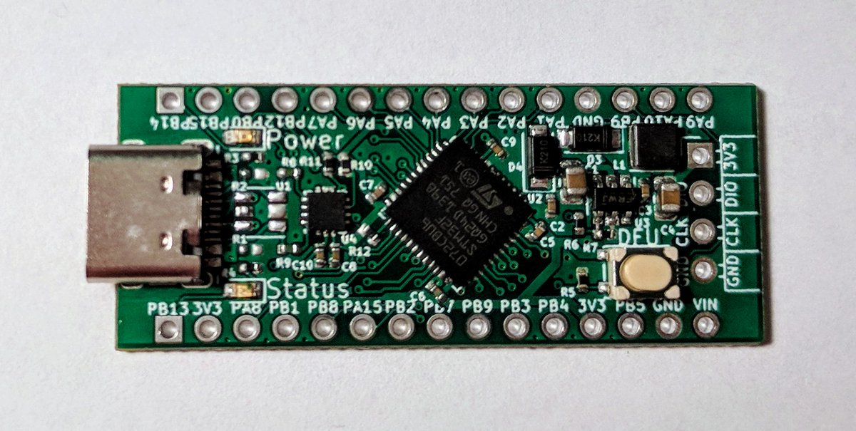
STM32 was one of the names that were almost driven into oblivion, no thanks to the Arduino Revolution, but the name was brought back into the limelight when the STM32 Blue Pill was released. With its compatibility with the Arduino IDE via the STM32duino support package and its breadboard friendly form factor, it was a new beginning for STM32 and things have not slowed down with several other boards like the Black Pill sharing the spotlights with several other developments board. However, things took a further upswing recently when Jan Henrik decided to take things further and create a better board. The result of this voyage by Jan is the OtterPill.
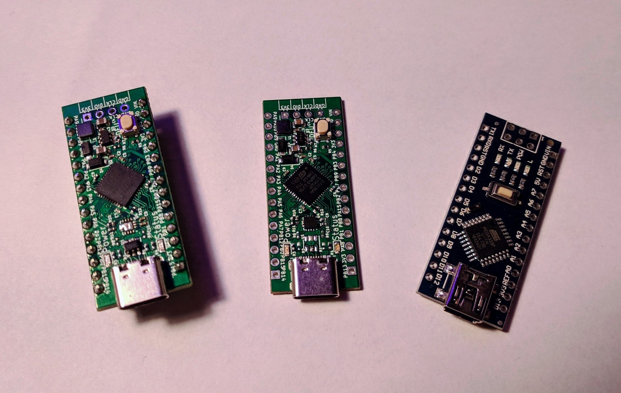
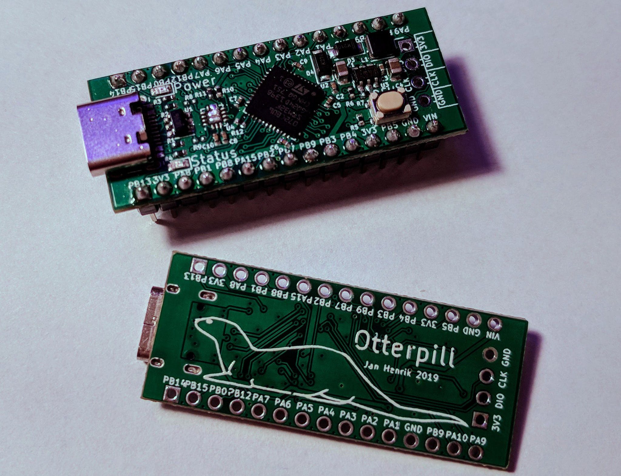
OtterPill (left and center), Arduino Nano (right)
The Otterpill is a 32-bit development board is based on the ARM Cortex Mo Core-based, STM32F072 microcontroller, and it comes in a form factor similar to that of the Arduino Nano with a pin-out that corresponds to that of the Arduino Nano where possible. For instance, the power special purpose pins like the I2C lines, UART and SPI pins, along with power and ground on the OtterPill, are located on the same spot/pins as the Arduino Nano.
The OtterPill sports a USB-C port like most recent development boards and like the Blue Pill, it can also be programmed using the Arduino IDE. As similar to the OtterPill is to the Bluepill, a few differences however exist starting from allowing users to reprogram the board through the DFU mode, using the dfu-util utility to flash the board. The Otterpill also comes with a USB Power Delivery (USB-PD) physical interface chip which makes it possible to power the board and connected peripherals/components with up to 20V supply voltage. In place of the USB-PD PHY chip, users can decide to power the board by using resistors to force a USB-C supply to provide 5volts and up to 3amps.
While this may change in the near feature, for now, the OtterPill is not available for sale anywhere but the design files, which were created using Kicad, are open-source and are available on the project’s Github page, so you download them make your own version of the board. The Github Repo also contains example firmware and documentation for the project.
In one of our previous articles, we built a DIY air quality monitor which was based on measuring the amount of Hydrocarbon concentration in the air using the BME680 VOC Whisker. While things work quite well using that method, there are several other parameters and air constituents which also have the same devastating effect and may be present in the air, but not detected by the sensor used in our previous project. One of such easy to overlook, constituents of air is Particulate Matter, and for today’s tutorial, we will build a device to measure its concentration in air.
Particulate matter is the sum of all solid and liquid particles (many of which are hazardous) suspended in the air. It is a complex mixture of organic and inorganic particles, such as dust, pollen, soot, smoke, and liquid droplets. These particles are created mostly when fuel is burnt and when the dust is carried by the wind. They vary greatly in origin, composition, and size which is the most popular way of categorizing them with the PM10 and PM2.5 classification.
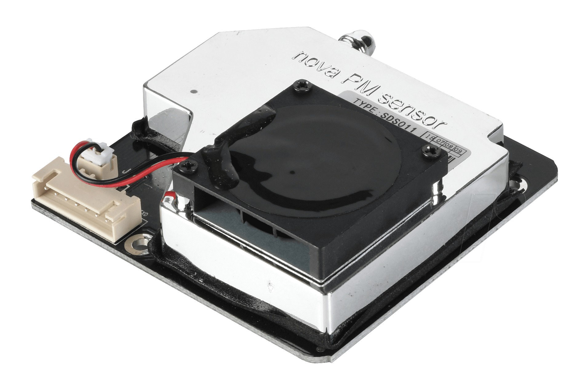
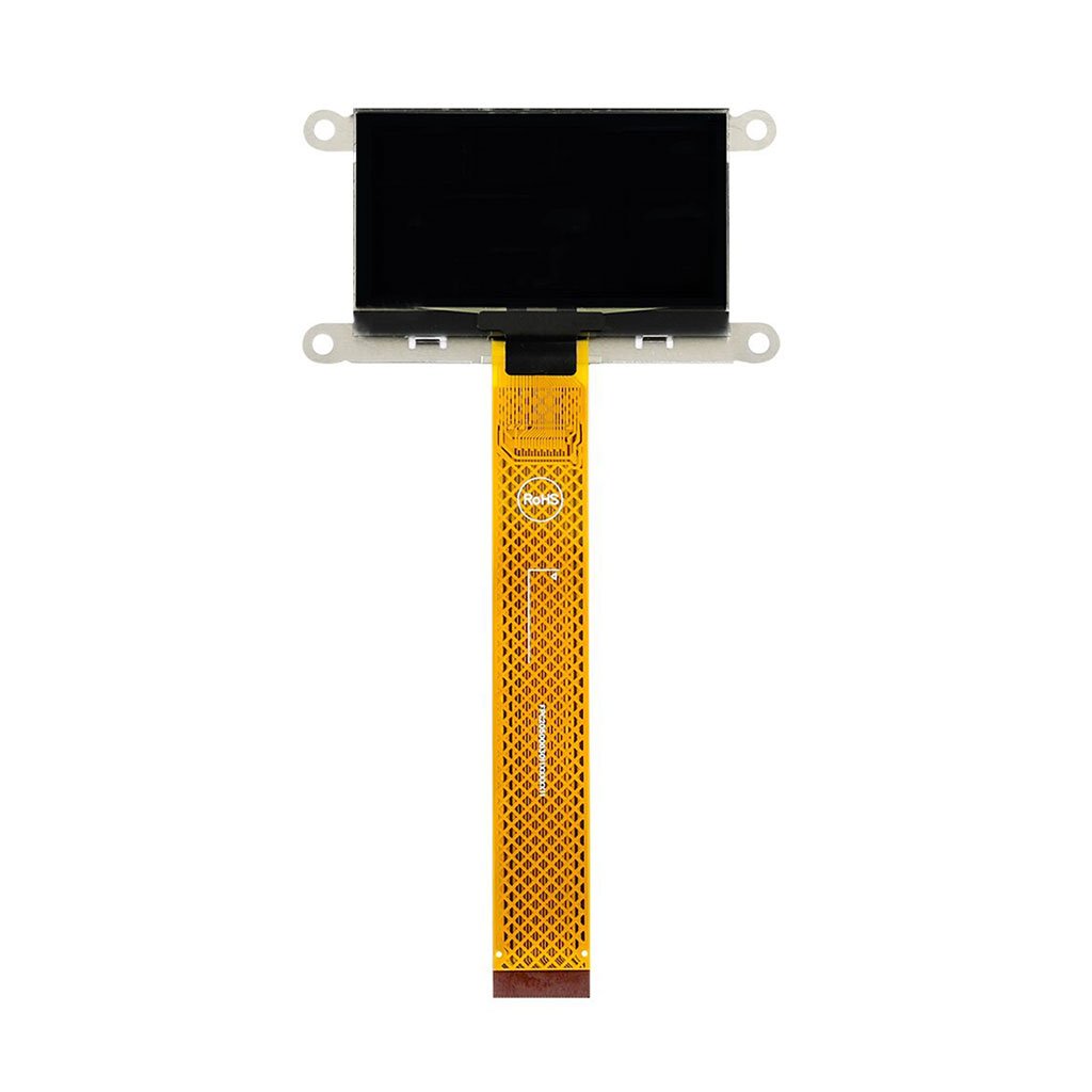
SDS011 Particulate matter Sensor
For today’s tutorial, we will build a device capable of determining the amount of particulate matter in the air around it. The device will be capable of monitoring PM10 and PM2.5 grade particles and display results on an OLED Display. The value displayed can be used in advising the users to wear a face mask or adopt other ways to protect themselves from polluted air.
While there are several projects on the internet measuring particulate matter, today’s project will be chronicling the efforts of user “plouc68000″ due to the low power features implemented which enabled the use of batteries in powering the device. The PM10 Dust Analyzer built by “plouc68000” is based on the Nova PM sensor: SDS011 combined with an I2C OLED on which the measurements are displayed in big digits so it is clear and easy to read.
At the end of this tutorial, you would know how to work with the Nova PM Sensor, the I2C OLED Display and also build your own air quality monitor.
Required Components
The following components are required to build this project:
The exact components used for the tutorial can be bought from the links attached to them.
Schematics
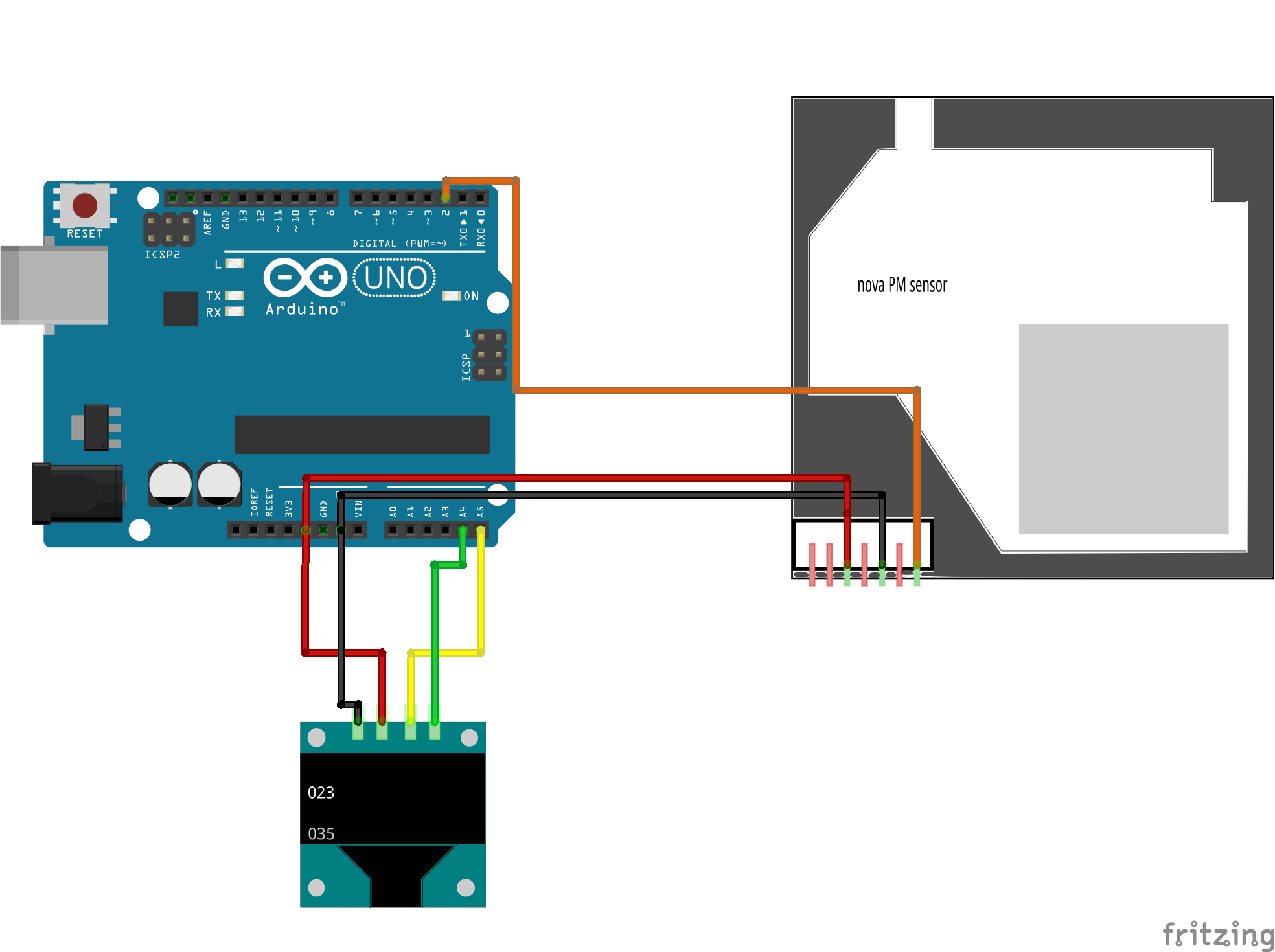
The schematics for this project is quite straightforward. The OLED display is connected to the Uno via the I2C pins (A4 and A5) while the output pin of the NOVA PM sensor is connected to a digital pin on the Uno. For the sake of this project, it was connected to pin D2 on the UNO.
The schematics showing how the components are connected is provided in the image below.
Schematics
To make the connection even easier to follow, a pin to pin map showing how the components connect to the Arduino is provided below:
Arduino – OLED
5V - VCC
A4 - SDA
A5 - SCL
GND - GND
Arduino – SDS011
GND - GND
5V - VCC
D2 - Dout
Code
As mentioned during the introduction, our goal for today’s project is simple and the code, straightforward. We analyze the Particulate Matter content of the air around us using the SDS011 PM sensor and display the value obtained on the OLED display.
To achieve this, we will develop the code using the Arduino IDE. This means the code will be in the familiar Arduino version of the C/C++ programming language.
To reduce the work involved in developing the code for the project, we will use two major libraries including; The U8glib and the Software Serial library. The Software Serial library is used to interact with the SDS011 sensor while the U8glib library is used to interact with the OLED display. While the Software Serial library comes preinstalled on the IDE, the U8glib can be downloaded and manually installed via the attached link.
As usual, I will do a quick explanation of some snippets/parts of the code which I feel may be slightly difficult to follow. We start the sketch, like always, by including all the libraries that we will be using. They are essentially the same as the ones mentioned above.
#include "SoftwareSerial.h"
#include "U8glib.h"
Next, we create an object of both libraries along with some global variables that will hold readings for PM10 and PM2.5.
SoftwareSerial mySerial(2, 3); // RX, TX for SDS011 sensor ( to keep Serial monitor available )
U8GLIB_SSD1306_128X64 u8g(U8G_I2C_OPT_NONE);  // for 1306 type OLED, I2C / TWI

// Global Variables
static unsigned char buf[7], buffSDS[25];
unsigned int PM2_5,PM10=0;
Next, we create two(2) functions/Subroutines. The first one is the void draw() function which is used in displaying all kinds of data on the OLED, while the second is the Val_to_string() function which is used to convert “int” into buf[] to BCD string so it can be displayed on the OLED.
// Sub Routines

// Update OLED Display
void draw(void) {
  /* for the line with PM2.5 value */
  if ( PM2_5>999 ) PM2_5=999 ;// overflow is 999
  val_to_string(PM2_5);

  u8g.setFont(u8g_font_fub30);// Large font
  u8g.drawStr( 0, 31, buf); //
  u8g.setFont(u8g_font_unifont);
  u8g.drawStr( 75, 10, "PM2.5");
  buf[0]='µ';
  buf[1] = '\0';
  u8g.drawStr( 75, 10+2+10, buf);
  u8g.drawStr( 82, 10+2+10, "g/m3");

  // for the line with PM10 value
  if ( PM10>999 ) PM10=999 ;// overflow
  val_to_string(PM10);

  u8g.setFont(u8g_font_fub30);// Large font
  u8g.drawStr( 0, 65, buf); //
  u8g.setFont(u8g_font_unifont);
  u8g.drawStr( 75, 34+10, "PM10");
  buf[0]='µ';
  buf[1] = '\0';
  u8g.drawStr( 75, 34+10+2+10, buf);
  u8g.drawStr( 82, 34+10+2+10, "g/m3");
}


/* convert int into buf[] to BCD string to be OLED printed */
void val_to_string(int val){

  int deca[5];
  deca[4]=10000;
  deca[3]=1000;
  deca[2]=100;
  deca[1]=10;
  deca[0]=1;

  char digit[10];
  digit[0]='0';
  digit[1]='1';
  digit[2]='2';
  digit[3]='3';
  digit[4]='4';
  digit[5]='5';
  digit[6]='6';
  digit[7]='7';
  digit[8]='8';
  digit[9]='9';

  buf[0]='0';
  buf[1]='0';
  buf[2]='0';
  buf[3]='\0'; // string terminator, only 3 digits needed
  buf[4]='0';
  buf[5] = '\0'; // not used

  for ( int8_t i=2; i>=0 ; i=i-1 )
  {
    byte d=0;
    while (( val-deca[i]) >= 0)
    { val=val-deca[i];
      buf[2-i]=digit[++d];
    }
  }
}
With the functions in place, we now proceed to the void Setup() function. We start the function by setting the color index to a single color (monochrome) to aid the clarity with which the data is displayed.
Next, we, initialize serial communication between the Uno and the SDS011, setting its timeout and stop bytes.
// Read SDS011 on Serial
mySerial.begin(9600);  //
mySerial.setTimeout(200);
mySerial.readBytesUntil(0xAB,buffSDS,20); // read serial until 0xAB Char received
We wrap up the function by initializing the hardware serial communication to enable us to use the serial monitor for debugging purposes.
// Serial Monitor
Serial.begin(115200);
}
With that done, we move to the void loop function.
We start the loop function displaying the first page which is meant to serve as a home screen.
Next, we read the SDS011 and print the data read on the serial monitor.
// Read SDS011
mySerial.readBytesUntil(0xAB,buffSDS,20);
// Serial monitor, print the HEX bytes received in buffSDS
//Serial.write(buffSDS,10);
for ( int8_t i=0; i<10 ; i=i+1 )
{
Serial.print( buffSDS[i],HEX);
Serial.print(" ");
}
Serial.println("");
The level of PM 2.5 present in the air is then obtained and the same is done for the PM10. The values obtained are then displayed on the serial monitor and the OLED. A small delay is added at the end of the code to ensure stability in readings.
With that done. we are ready to upload the code and test things out.
The complete code for the project is available below and also attached under the download section.
// UNO version of PM10 Analyser
#include "SoftwareSerial.h"
#include "U8glib.h"
SoftwareSerial mySerial(2, 3); // RX, TX for SDS011 sensor ( to keep Serial monitor available )
U8GLIB_SSD1306_128X64 u8g(U8G_I2C_OPT_NONE); // for 1306 type OLED, I2C / TWI
// Global Variables
static unsigned char buf[7], buffSDS[25];
unsigned int PM2_5,PM10=0;
// Sub Routines
// Update OLED Display
void draw(void) {
/* for the line with PM2.5 value */
if ( PM2_5>999 ) PM2_5=999 ;// overflow is 999
val_to_string(PM2_5);
u8g.setFont(u8g_font_fub30);// Large font
u8g.drawStr( 0, 31, buf); //
u8g.setFont(u8g_font_unifont);
u8g.drawStr( 75, 10, "PM2.5");
buf[0]='µ';
buf[1] = '\0';
u8g.drawStr( 75, 10+2+10, buf);
u8g.drawStr( 82, 10+2+10, "g/m3");
// for the line with PM10 value
if ( PM10>999 ) PM10=999 ;// overflow
val_to_string(PM10);
u8g.setFont(u8g_font_fub30);// Large font
u8g.drawStr( 0, 65, buf); //
u8g.setFont(u8g_font_unifont);
u8g.drawStr( 75, 34+10, "PM10");
buf[0]='µ';
buf[1] = '\0';
u8g.drawStr( 75, 34+10+2+10, buf);
u8g.drawStr( 82, 34+10+2+10, "g/m3");
}
/* convert int into buf[] to BCD string to be OLED printed */
void val_to_string(int val){
int deca[5];
deca[4]=10000;
deca[3]=1000;
deca[2]=100;
deca[1]=10;
deca[0]=1;
char digit[10];
digit[0]='0';
digit[1]='1';
digit[2]='2';
digit[3]='3';
digit[4]='4';
digit[5]='5';
digit[6]='6';
digit[7]='7';
digit[8]='8';
digit[9]='9';
buf[0]='0';
buf[1]='0';
buf[2]='0';
buf[3]='\0'; // string terminator, only 3 digits needed
buf[4]='0';
buf[5] = '\0'; // not used
for ( int8_t i=2; i>=0 ; i=i-1 )
{
byte d=0;
while (( val-deca[i]) >= 0)
{ val=val-deca[i];
buf[2-i]=digit[++d];
}
}
}
void setup() {
// put your setup code here, to run once:
// init 1306 I2C OLED
u8g.setColorIndex(1); // monochrome
// Read SDS011 on Serial
mySerial.begin(9600); //
mySerial.setTimeout(200);
mySerial.readBytesUntil(0xAB,buffSDS,20); // read serial until 0xAB Char received
// Serial Monitor
Serial.begin(115200);
}
void loop() {
 // LCD Update
  u8g.firstPage();
  do {
    draw();
  } while( u8g.nextPage() );
// Read SDS011
mySerial.readBytesUntil(0xAB,buffSDS,20);

// Serial monitor, print the HEX bytes received in buffSDS
//Serial.write(buffSDS,10);
for ( int8_t i=0; i<10 ; i=i+1 )
  {
  Serial.print( buffSDS[i],HEX);
  Serial.print(" ");
  }
Serial.println("");
PM2_5 = ((buffSDS[3]*256)+buffSDS[2])/10; // extract PM2.5 value
Serial.print("PM2.5: ");
Serial.println(PM2_5);

PM10 = ((buffSDS[5]*256)+buffSDS[4])/10; // extract PM10 value
Serial.print("PM10: ");
Serial.println(PM10);

delay(500);
}
Demo
Launch an instance of the Arduino IDE, copy the code above and paste it in the IDE. Connect your Arduino Uno or any other board you decide to use, select the appropriate board type and port, then hit the upload button.
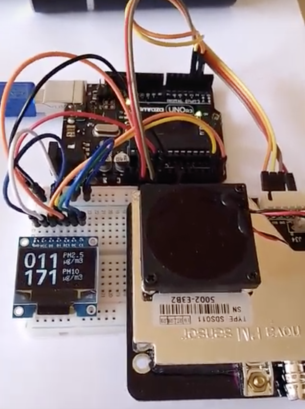
With the upload completed, you can test the project by bringing something with dust close to the device’s air intake or take the device to a dusty environment. After a few minutes, you should see the value PM10 and PM 2.5 values being displayed on the OLED display, rise in proportion to the amount of dust discovered by the device as shown in the image below.
Demo
Going Forward
An obvious, super cool, next step will be to merge this project with the last project which measures the concentration of hydrocarbons in the air. Combining these two will provide a wider and more accurate base for us to measure the air quality index. The data can also be connected to the cloud to share the data with others, transforming the project into an IoT endeavor.
That’s it for this tutorial. As usual, feel free to reach out to me via the comment section with questions as regards the project. A video of the project in action as created by plouc68000 is available on youtube.
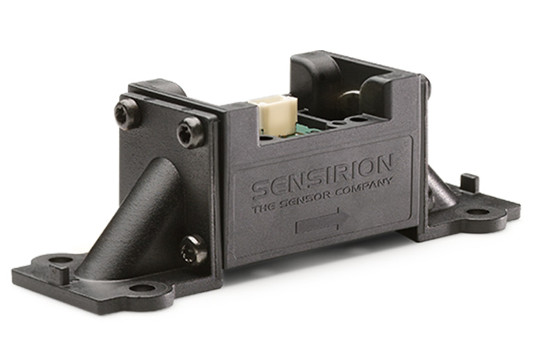
The mass flow meter SFM4300 features improved sensitivity and precision, even for low flow rates.
The small, compact sensor is calibrated for air, O2 and N2O gases and – in contrast to its predecessor, the mass flow meter SFM4100 – it can also be used to monitor gas mixing. With a zero-point accuracy of 0.005 slm for a total range of up to 20 slm, the SFM4300 enables precise adjustment of the concentration in a wide selection of mixtures. The sensor unit has an I²C interface and produces a fully calibrated and temperature-compensated output signal. The mass flow sensor can be used for both medical and industrial gas mixing, fuel cells and for other OEM applications.
Features
Compact
High precision and sensitivity (esp. for low flow rates)
Flow range: 0 to 20 slm
Very pressure-resistant (up to 6 bar)
Multigas option: O2, air, NO2 (other calibrations on request)
Flow Sensors for Gas Mixing in Respiratory Devices
In addition to inspiratory, expiratory and proximal flow measurement, Sensirion offers sensor solutions for gas mixing applications. These sensors are mainly used in anesthesia machines and are usually integrated into the overall machine. If we want to guarantee the patient’s safety while taking accurate, reproducible readings, we need the flow sensors in the machine to be stable and reliable – throughout the machine’s service life. Therefore, the Sensirion SFM4000 series is the ideal solution. It is is devided in two sensors: SFM4300 and SFM4200. The SFM4300 sensor can operate at pressures of up to 6 bar, store multiple gas calibrations and even perform self-testing while in use. Where safety and reliability are concerned, the SFM4300 is the preferred choice. The SFM4200 sensor is highly resistant to pressure, it guarantees reliable measurements at surges of up to 8 bar. Its signal processing time is 0.5 ms, making it incredibly fast and accurate. Customers also benefit from an expanded measurement range of up to 160 liters per Minute.
For information about the SFM4300 visit the product page on the official website of Sensirion.
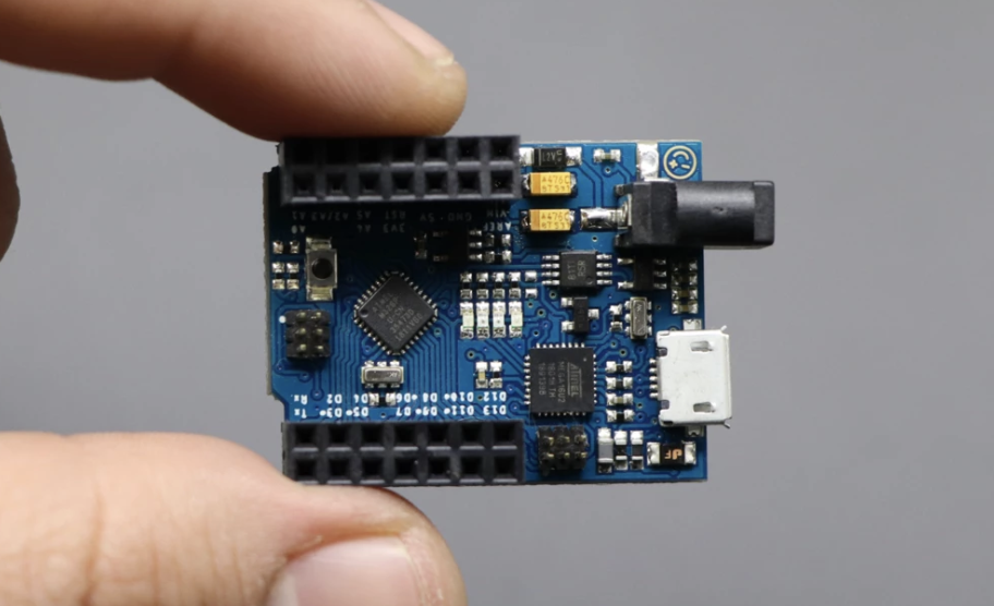
The Arduino Uno is unarguably one of the greatest development boards ever made and its impact as one of the boards that rekindled the fire of the electronics maker movement cannot be disputed. It came with enough power for users to build amazing projects, but it also was extremely easy to use making it a superb platform for learning electronics. However, there was one “shortcoming” users couldn’t ignore; the size of the Uno. While this was not a problem for professionals and semi-professionals who could easily migrate their project to an ATmega328p chip after prototyping with the Uno, it was a problem for beginners who would like to use the entire board in their project. Several projects have made attempts at modifying the size, from projects like “barebone Arduino” to several “Arduino on Breadboard” projects but none of this projects has however been able to put together all the features of the Uno on a small form factor like Mellbell recently did with the minUno development Board.
The miniUno is an exact replica of the Arduino Uno only that it is a quarter the size of the Uno, measuring only 1.35″ x 1.05″ compared to the 2.7″ x 2.1″ dimensions of the Arduino Uno. True to Mellbell’s claims about the board retaining the strength of the Arduino Uno, the miniUno is based on the Atmega328p (same microcontroller on the Arduino Uno), sports 14 digital I/O pins (6 of which can be used as PWM outputs), 6 analog input, a micro USB port, a power jack, and ready to go plug and play compatibility with the Arduino IDE.
The board was a follow up development to the Pico (“smallest Arduino Board”) which was launched by Mellbell a while back and retains the Popular MicroUSB ports (definitely one of the contributors to the reduced sized) which in conjunction with the pre-flashed bootloader on the board, allows seamless connection to the Arduino IDE, straight out of the box.
Some of the highlight features of the miniUno are listed below:
Size: 1.35″ x 1.05″
Weight: 5.5 grams
Digital I/O pins: 14 (of which 6 provide PWM output)
PWM Digital I/O Pins: 6
Analog Input Pins: 6
DC Current per I/O Pin: 20mA
DC Current for 3.3V Pin: 50mA
Microcontroller: ATmega328P
Operating Voltage: 5V
Input Voltage (recommended): 7-12V
Input Voltage (limit): 6-20V
Flash Memory: 32 KB (ATmega328P) of which 0.5 KB used by bootloader
SRAM: 2 KB (ATmega328P)
EEPROM: 1 KB (ATmega328P)
Clock Speed: 16 MHz
LED_BUILTIN: Yes (PIN 13)
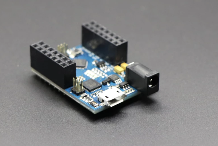
The MiniUno
Standard pin headers were used on the miniUno making it easy to use with breadboards. The board’s performance has been likened to that of the Arduino Uno with the only thing missing being the huge size of the Uno
The MiniUno is currently available for sale on Mellbell’s website for $21 with a discount of up to $4 when you buy 20 of the boards. More information about the boards is available on the product page.
If you have ever considered the option of using encryption in your design, then you should be able to perform a side-channel attack as well as understand the consequences of such an attack on your product. While oscilloscopes and differential probes can be helpful in traditional power analysis attacks especially at the initial stage, these tools can be a bit of overkill for most analyses and also very expensive.
The ChipWhisperer series aims at nothing short of causing a fundamental change in the entire embedded security industry. A combination of documentation, training, open-source software and hardware makes it easy to master hardware security problems.
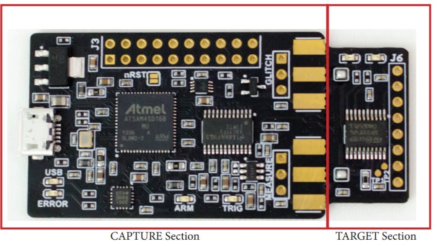
Whisperer Nano
The new ChipWhisperer-Nano from NewAE technology is a small form factor tool that contains a capture device as well as an STM32- based target both for side-channel attacks and for learning. Designed primarily for power analysis demonstrations and training programs, this latest release in the ChipWhisperer series is an ultra-low-cost platform for voltage fault injection and side-channel analysis.
Some of the features of the Chip Whisperer Nano include:
STM32F030 target for loading example code and a programmer built into the CWNANO.
Crowbar based VCC glitching with about 10nS resolution on the width of the glitch and glitch offset from the trigger with up to 200nS jitter.
ADC for sampling up to 20MS/s with either an internal clock (both synchronous and asynchronous) or an external clock (synchronous to the device).
ADC hardware trigger that uses rising-edge input and samples for user-configurable length.
The ChipWhisperer NANO’s capture hardware has a dedicated 8-bit ADC chip interfaced with a microcontroller which helps to sample the power rail and provide information back to the software. It then provides frequency and timing analysis of the power signal while the target runs its algorithms.
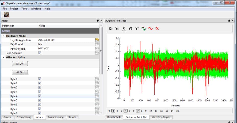
Example of Chipwhisperer Analyzer Software
Although the ChipWhisperer Nano lacks some other glitching features when compared with the other larger and more expensive tools in the SCA tool portfolio like the Pro and Lite, the ChipWhisperer Nano is an excellent learning tool with an estimated BOM cost of about $20 for a single unit.
The nature of the ChipWhisperer, being open source also makes it possible to engage the research community at large and at the same time, provides low-cost reference hardware. The Jupyter-based documentation provides examples like analysis for password bypass and AES attacks using different techniques.
To download the open-source software and various hardware options including the PDF schematic of the CWNANO, you can visit the ChipWhisperer GitHub repo or check ChipWhisperer-Nano website for information specific to the product.
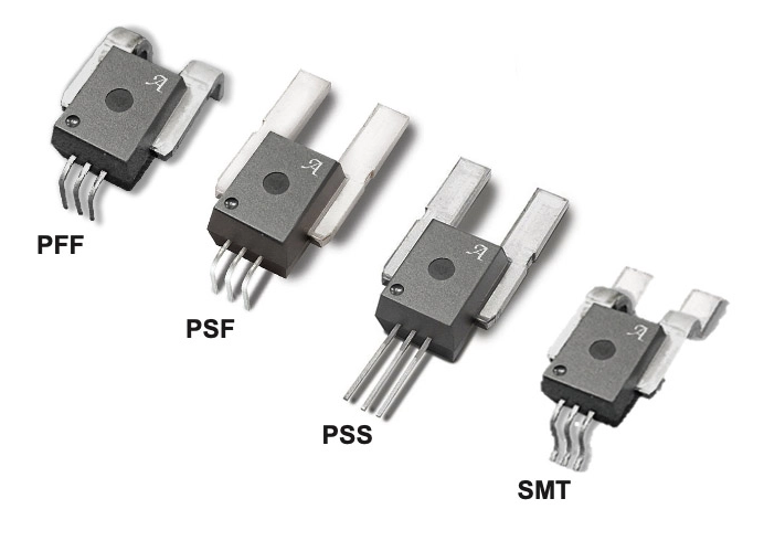
The ACS772/3 family expands to include through-hole and surface-mount CB package options with enhanced working isolation voltage
Allegro MicroSystems, a global leader in power and sensing solutions for motion control and energy efficient systems, today announced significant ease-of-use enhancements to its popular high current fully integrated ACS772/3 current sensor “CB” package family.
These industry-leading, automotive grade high voltage isolation current sensors already provide economical and precise solutions for both AC and DC current sensing up to 400A. Building on that leadership and deep customer-understanding, Allegro’s new surface-mount leadform option for the CB package is the answer to many customer challenges by providing a flexible solution for space constrained applications.
“This is a classic, ‘You asked – we listened.’ innovation with purpose moment for us,” explains Shaun Milano, Business Unit Director for Current Sensors. “Our customers want flexibility, and we’re excited to provide these innovative, robust solutions in this new surface-mount option to complement our highly popular through-hole version. High current PCB designs improve power density and efficiency and this surface-mount option allows customers to realize these advantages with a simpler manufacturing process.”
The ACS772/3 family of current sensor ICs has an enhanced feature set that helps engineers simplify their bill of materials and improve efficiency in the toughest of applications:
Small form footprint over competing solutions
Very fast 2.5uS response time that enables overcurrent fault detection – ideal for safety-critical applications
Enhanced working isolation voltages up to 1300V+ for basic DC voltage, and 650V+ for reinforced isolation DC voltage – No need for opto-isolators or other costly isolation techniques.
High accuracy of +/-2.1% over the lifetime of the IC
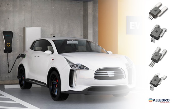
These features make the ACS772/3 family ideal for a range of applications from industrial robotics to electric vehicles.
“Many of our customers, especially in green energy applications, are looking for higher working voltages which can provide efficiency improvements and cost reductions in their systems,” said Milano. “In solar applications for instance, raising the system voltage allows for longer strings, which eliminates significant wiring and connector combiner boxes. It also allows for longer panel strings with higher rated output inverters, which reduces losses and improves efficiency. These improvements are a win-win for our customers.”
For more details on the ACS772/3 family, including the new surface-mount option, and to learn more from Allegro’s current sensor team:
Visit the ACS772 and ACS773 product pages for device specifications and the datasheets.