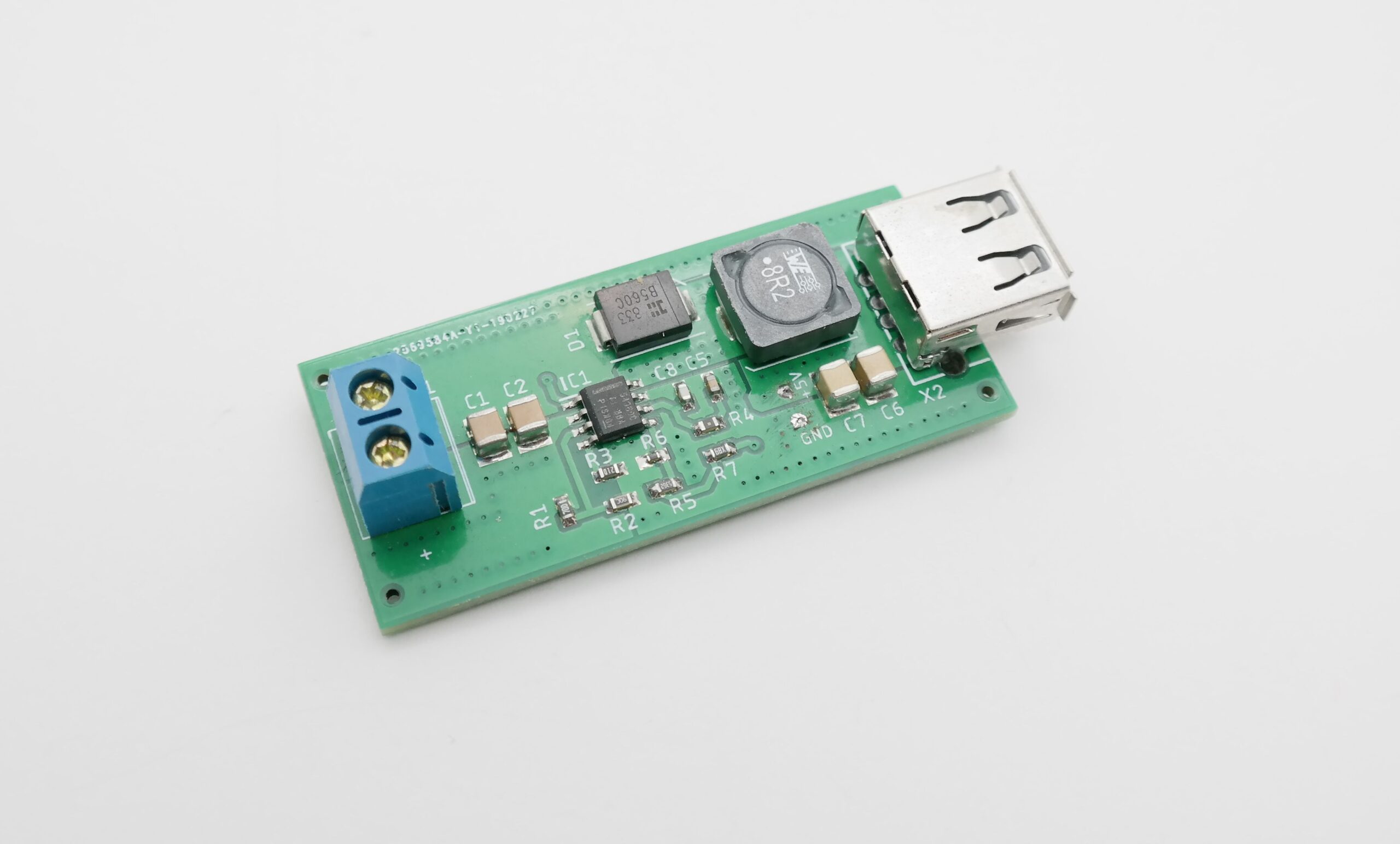
This is a 60V to 5V – 3.5A step down DC-DC converter based on TPS54360B from Texas Instruments. Sample applications are: 12 V, 24 V and 48 V industrial, Automotive and Communications Power Systems. The TPS54360 is a 60V, 3.5A, step down regulator with an integrated high side MOSFET. The device survives load dump pulses up to 65V per ISO 7637. Current mode control provides simple external compensation and flexible component selection. A low ripple pulse skip mode reduces the no load supply current to 146 μA. Shutdown supply current is reduced to 2 μA when the enable pin is pulled low.
Under-voltage lockout is internally set at 4.3 V but can be increased using the enable pin. The output voltage start up ramp is internally controlled to provide a controlled start up and eliminate overshoot. A wide switching frequency range allows either efficiency or external component size to be optimized. Frequency fold back and thermal shutdown protects internal and external components during an overload condition.
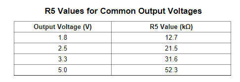
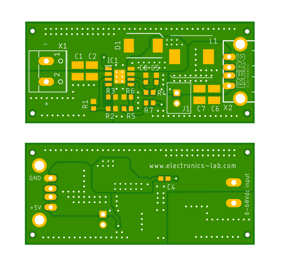
Note: The output voltage is set by a resistor divider from the output node to the FB terminal. It is recommended to use 1% tolerance or better divider resistors, choose R5, R6 for other output voltages.
It is strongly recommended to use adequate air flow over the board to ensure it doesn’t go at thermal shutdown. See thermal profile below.
Setting Output Voltage
The following table lists the R5 values for some common output voltages assuming R6= 10.0kΩ
Features
Supply Input 8.5V-60V
Output 5V (Output Voltage adjustable with R5, R6)
Output Current 3.5A
100 kHz to 2.5 MHz Switching Frequency
Optional JST connector for 5V Fan
Current Mode Control DC-DC Converter
Integrated 90-mΩ High Side N-Channel MOSFET
High Efficiency at Light Loads with Pulse Skipping Eco-mode™
Low Dropout at Light Loads with Integrated BOOT Recharge FET
146 μA Operating Quiescent Current
1 µA Shutdown Current
Internal Soft-Start
Accurate Cycle-by-Cycle Current Limit
Thermal, Overvoltage, and Frequency Fold back Protection
PCB Dimensions 55.50mm x 24.64mm
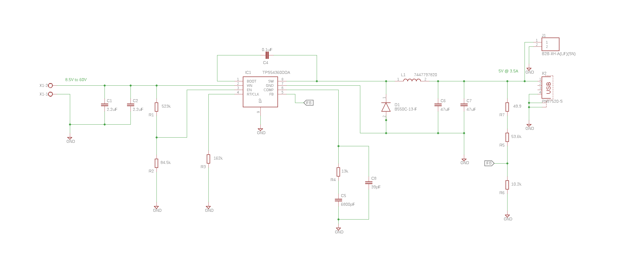
Schematic
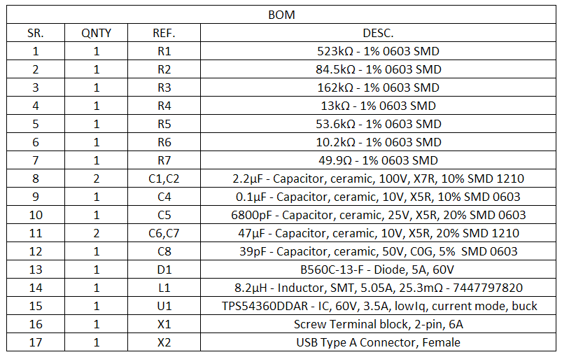
Parts List
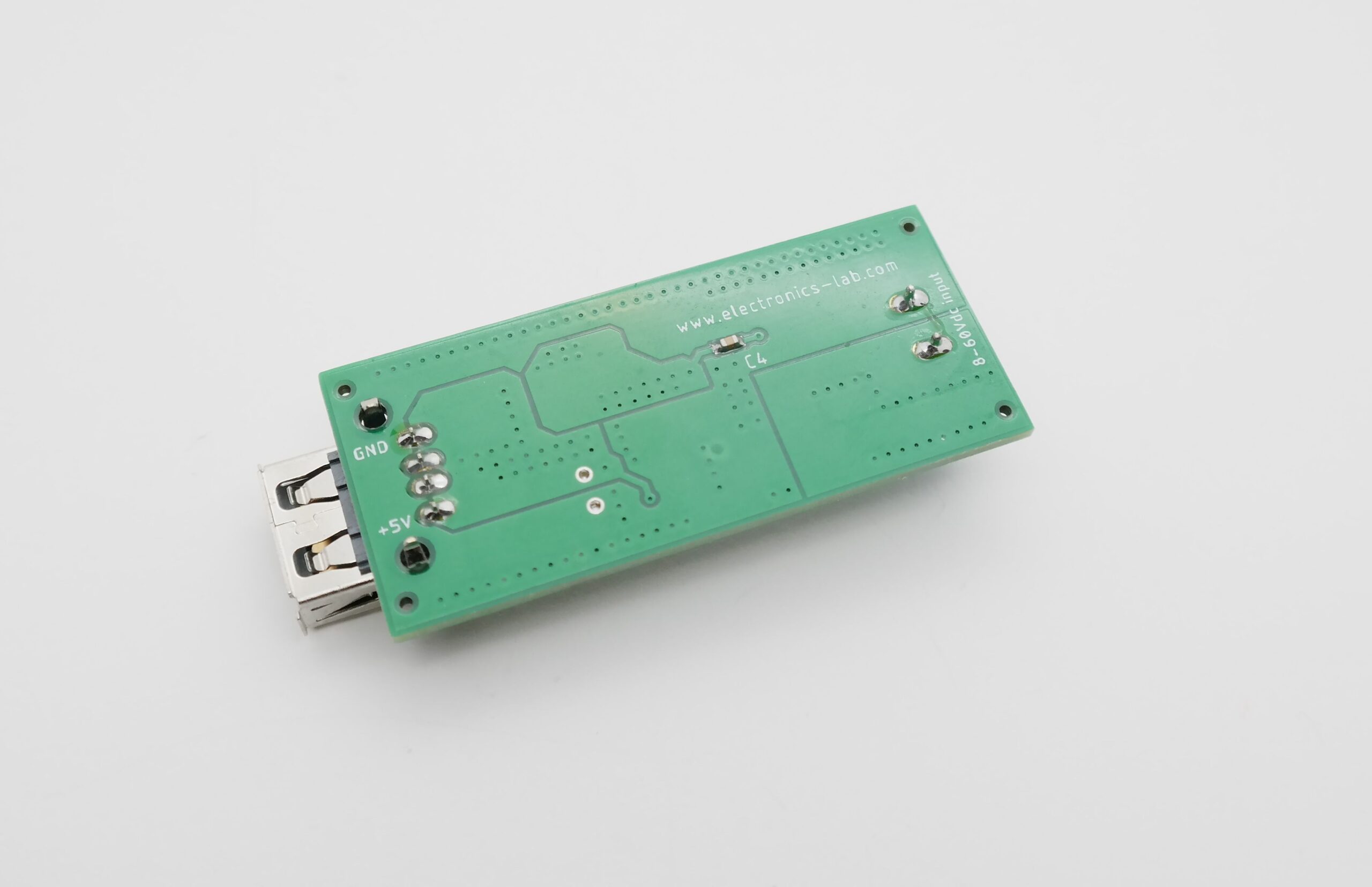
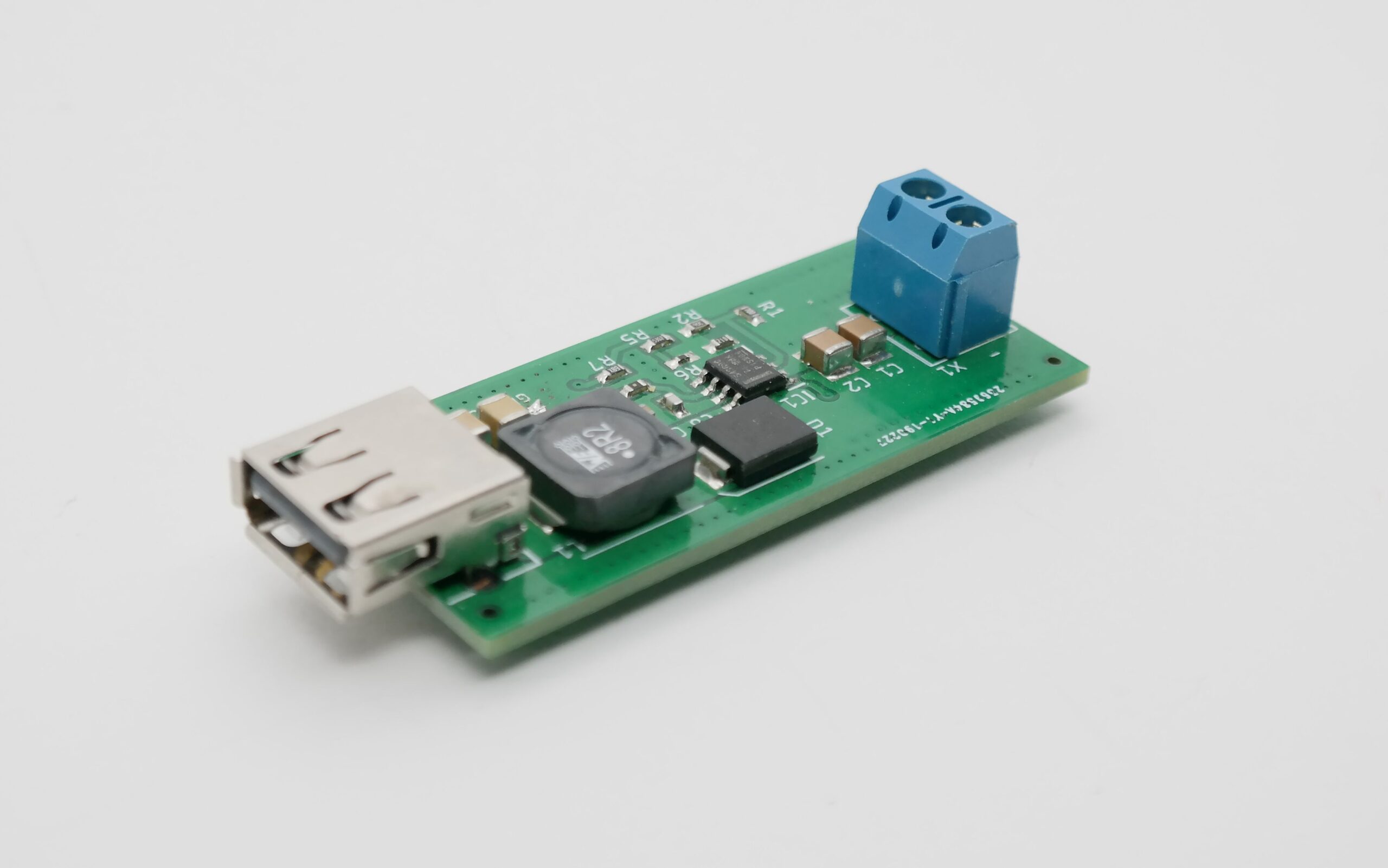
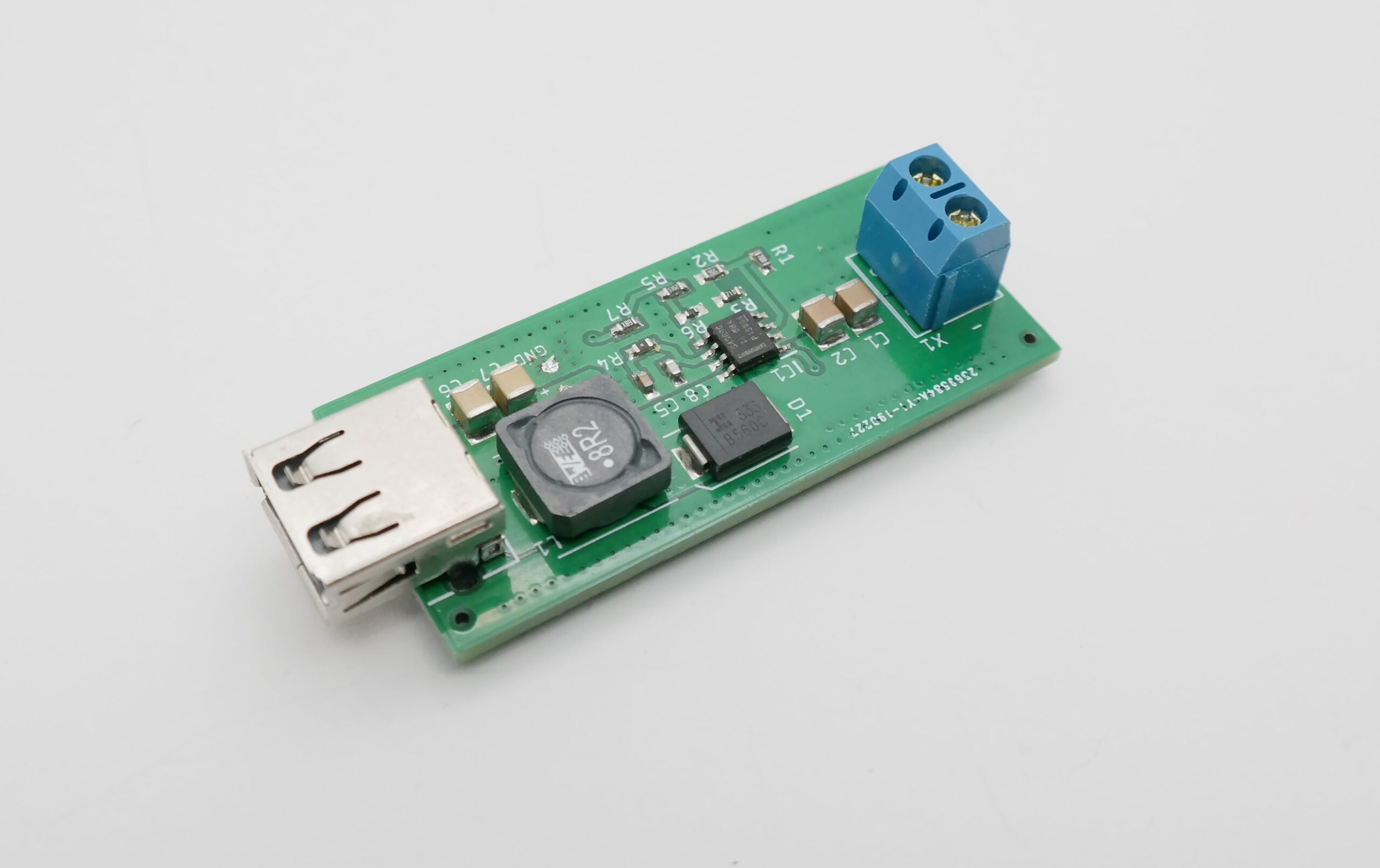
PCB
Thermal Image
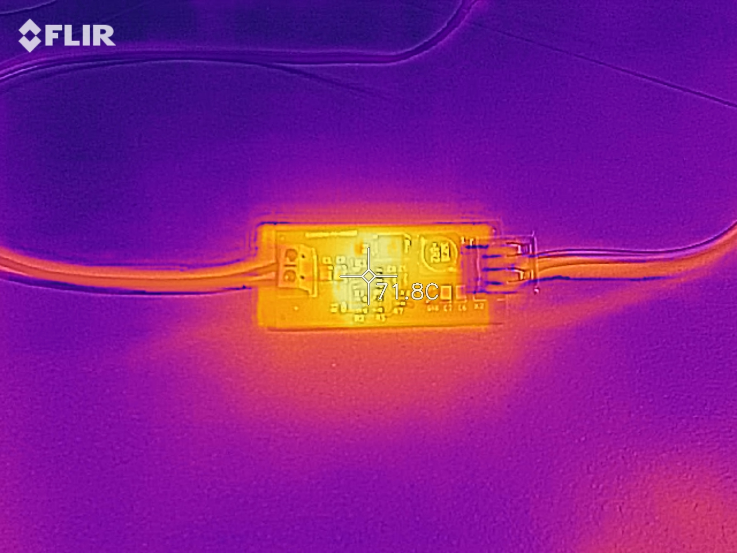
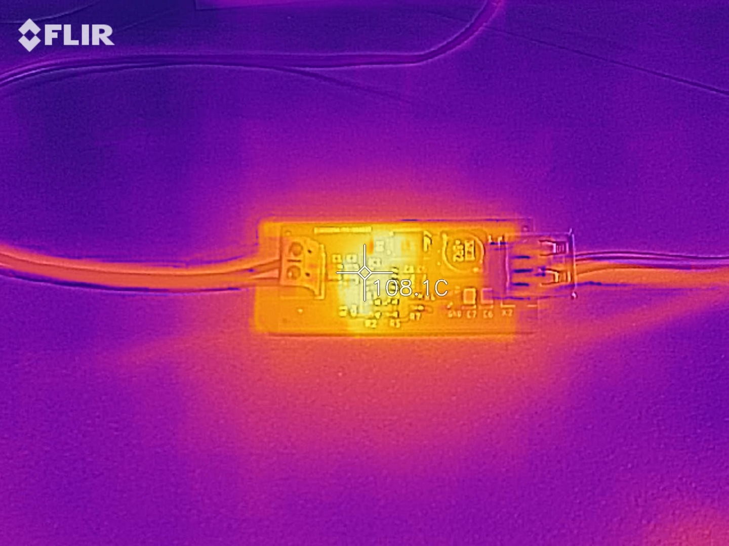
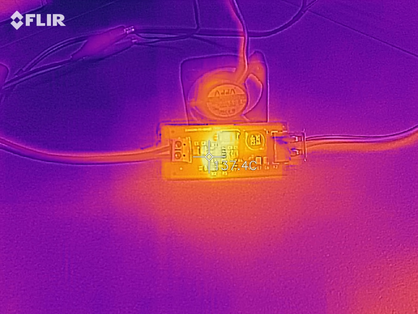
You can see on the thermal images below that at 60V input – 5V @2A output the IC gets too hot (>105ºC) and if we go for higher outputs (2.5-3A) the IC gets in thermal cut-off. To avoid this situation you can use a small 5V FAN to blow air on the board or probably use a heatsink attached to the board.
60V input – 5V @1A output60V input – 5V @2A output60V input – 5V @3A output cooled with a small FAN
Measurements
The efficiency is calculated based on the (Pout/Pin)*100%. For 60V input and 5V @3A output the input current is 0.32A, so Pin=19.38W. Pout=5V*3A=15W, so e=77.39% with Pdis = 4.58W
In one of our previous tutorials, we examined the development of a DIY-Geiger Counter showing the efforts of “Instructable” user Prabhat who combined the ESP8266 with a touch screen display to create a truly intuitive version of his Geiger Counter. He recently created an updated version and today’s tutorial will focus on how this new version of the Geiger Counter can be replicated. The Geiger counter is an instrument used for detecting and measuring ionizing radiation. It is one of the worlds best-known radiation detection instrument as it can be used to detect ionizing radiation such as alpha particles, beta particles, and gamma rays and its is usually used as a handheld radiation survey instrument, warning users when in the region of dangerous ambient radiation levels with an all-too-familiar clicking noise.
While this project retains some of the features from the first version, like the use of the ESP8266 and a touchscreen interface, rather than just implementing the detection of radiation levels like the first version, it combines a Geiger counter, a dosimeter and a radiation monitoring together in a single package that is 50% less thick, and with loads of new software features! Some of the new features include:
New and Improved Geiger Counter – Now With WiFi! – [Link]
ST Microelectronics’ ST730 is a 300 mA LDO regulator designed to be used in several medium voltage applications. Ultra-low quiescent current of 5 µA makes it suitable for applications permanently connected to power supply and battery. This feature is also useful when electronic modules remain permanently turned on. The ST730 embeds protection functions, such as current limit, short-circuit, and thermal shutdown. The extended input voltage range, very low drop voltage, and low quiescent current features make it suitable also for low-power after-market automotive and consumer applications.
Key Features
Wide input voltage range : 2.5 V to 28 V
Ultra-low quiescent current: typ. 5 μA at no-load, 10 μA max. across full temperature range, 1 μA max. in shutdown
High output voltage accuracy: ± 0.5% @ 25 °C, ± 1% across temperature range
Output current up to 300 mA
Fixed output voltage versions, starting from 1.2 V to 12 V with 100 mV step
Adjustable voltage version, starting from 1.2 V to VIN – VDROP
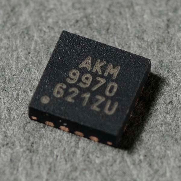
AKM’s AK09970D has 1/5 of the packaging area of the conventional AK09970N
AKM’s AK09970D is a device with a much smaller overall footprint than its conventional tri-axis magnetic smart switch sensor, the AK09970N. Mobile devices, such as smartphones and various wearable devices, can be equipped with this sensor that requires low power consumption and a high degree of freedom in placement. Applications include open/close, stroke, rotation, and push detection in mobile devices.
The AK09970D has a high sensitivity setting of 36mT on tri-axis. It is able to measure a wide range of magnetic field from microtesla to millitesla such as from geomagnetic to a magnet since it has high measurement resolution of 1.1µT/LSB in high sensitivity mode. In addition, wide range setting of 101mT can be achieved via the Z axis.
The AK09970D can operate using only a few µA, thus consuming a very low current that satisfies a demand of IoT products, (Refer to the Specification Table). It contributes to a long battery life of a product that needs constant acquisition of sensor data to monitor an object’s status.
The AK09970D measures magnetic field on all tri-axis via intermittent drive and outputs the result as digital data, (supporting I2C communications). It outputs a Data Ready alert to the dedicated register when the measurement data is updated. (0.25/0.5/1/10/20/50/100Hz interval modes or single measurement mode is selectable for intermittent drive options.)
The AK09970D has magnetic event interrupt pin. Two thresholds can be programmed for each axis, (setting the resolution equal to the measuring resolution). When a magnetic field that exceeds the threshold is sent, the AK09970D outputs a “Magnetic Event” interrupt to external output pin.
Features
Wide input voltage range: 2.5 V to 28 V
Ultra-low quiescent current: typ. 5 µA at no-load, 10 µA max. across full temperature range
Output current up to 300 mA
High output voltage accuracy: ±0.5% @ 25 °C, ±1% across temperature range
The new Binho multi-protocol USB host adapter powered by the USB connection to a host PC allows you to interface your computer directly to hardware circuits.
The Binho adapter has support for 12C @ 3.4 MHz max clock, SPI @12MHz max clock, Dallas 1wire, Atmel single wire interface, UART @ 1000000 max baud as well as support for ADC functionality. It also has a single-channel DAC output that can help in case you need to stimulate your circuit with a particular voltage. While in IO mode, its 5 signal pins can serve as digital input or output, digital interrupt, PWM output, or analog input or output while the remaining pins assigned to other related or unrelated purposes.
Some of the key features and details of the USB host adapter include:
Provides 3v3 and VUSB power rails
1 DAC outputs and 5 ADC inputs
Programmable RGB status LED
Cross platform support for Windows, Linux and Mac.
Support for GPIO/Interrupt/PWM
USB Type-C connector
Low-profile aluminum enclosure
Field upgradeable device firmware
With the Binho adapter, there is no constraint to a particular Operating System environment as the drivers are already included for most OS. The cross-platform software available for Mac, Windows and Linux, provides an easy-to-use GUI interface for your USB host adapter. The device is also able to provide downstream power to test circuits; for convenience’s sake, it makes available power source from the 3v3 rail or the 5V USB Bus power.
The Binho Multi-Protocol USB Host Adapter brings USB Host Adapters into the 21st Century. No more fumbling through development with cumbersome, clunky, out-dated adapters. Let your productivity soar to new heights!
The Binho multi-protocol USB host adapter is commonly used for development and testing purposes. It is used in production environment for some functional testing in Flash and EEPROM memory programming. It is also ideal for manual testing during system debugging and firmware development as well as to automate hardware testing.
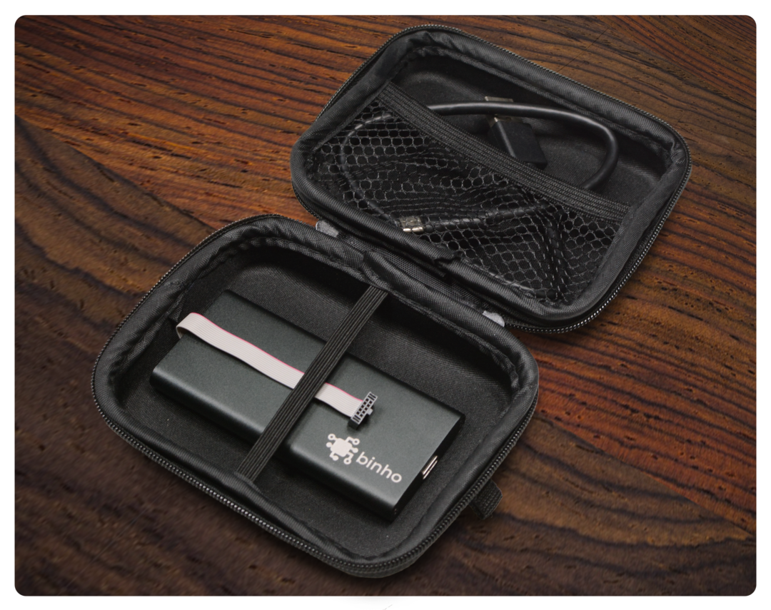
Built to last, Binho multi-protocol USB host adapter is covered completely against any malfunction or defect. Its anodized aluminum enclosure and low profile design makes it safe and easy to carry around.
With its robust package and support for multiple protocols all in one slim, Binho has become one of the most versatile USB host adapter available. The adapter aims at increasing productivity during development and it comes alongside a one foot USB Type C (male) to Type A (male) cable and a breadboard break out adapter in a soft-shell zippered case.
More information can be found on Binho’s website. It is currently being sold for $149.00 and shipping is done within 24 hours.
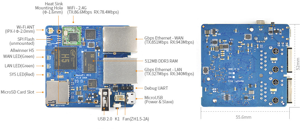
FriendlyELEC launched NanoPi R1 SBC & Gateway earlier this year with Allwinner H3 processor, two Ethernet ports, as well as WiFi and Bluetooth connectivity. The design makes use of both Ethernet on the processor, but that also means on Gigabit Ethernet port had to be combined with a Fast Ethernet processor.
The company has now added a USB to Gigabit Ethernet bridge to their latest NanoPi R1S board meaning it’s now a dual Gigabit Ethernet SBC, but with the caveat that the port behind the USB bridge is limited to USB 2.0 speed (480 Mbps), and with overhead the USB Ethernet bandwidth is around 330 Mbps.
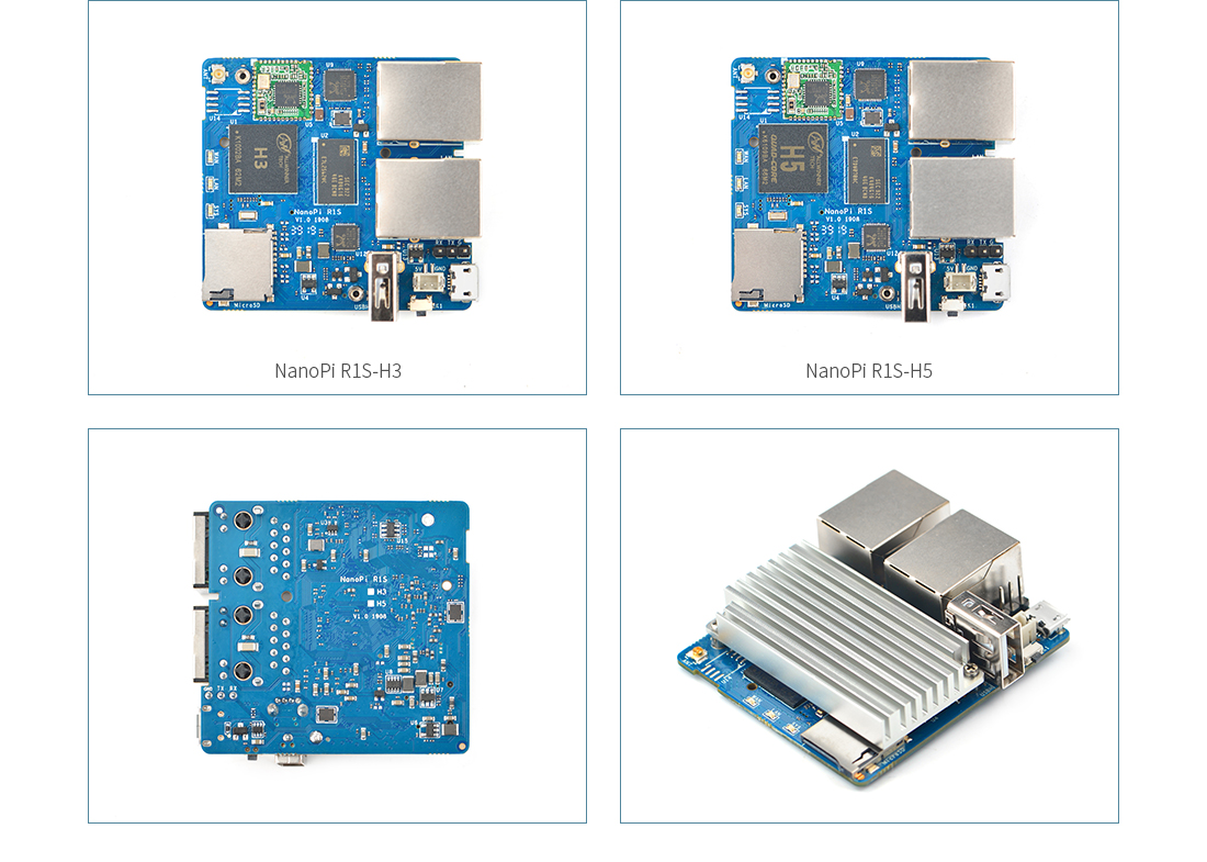
There are two versions of the board, namely NanoPi R1S-H3 and R1S-H5 with respectively Allwinner H3 32-bit processor, and Allwinner H5 64-bit processor.
Apart from the different processors, both boards share the same PCBA and specifications:
SoC
NanoPi R1S-H3 – Allwinner H3 quad-core Arm Cortex-A7 processor @ up to 1.2GHz with Mali-400MP2 GPU
NanoPi R1S-H5 – Allwinner H5 quad-core Arm Cortex-A53 processor @ up to 1.2GHz with Mali-450MP GPU
System Memory – 512MB DDR3 RAM
Storage – MicroSD Slot, SPI flash footprint
Connectivity
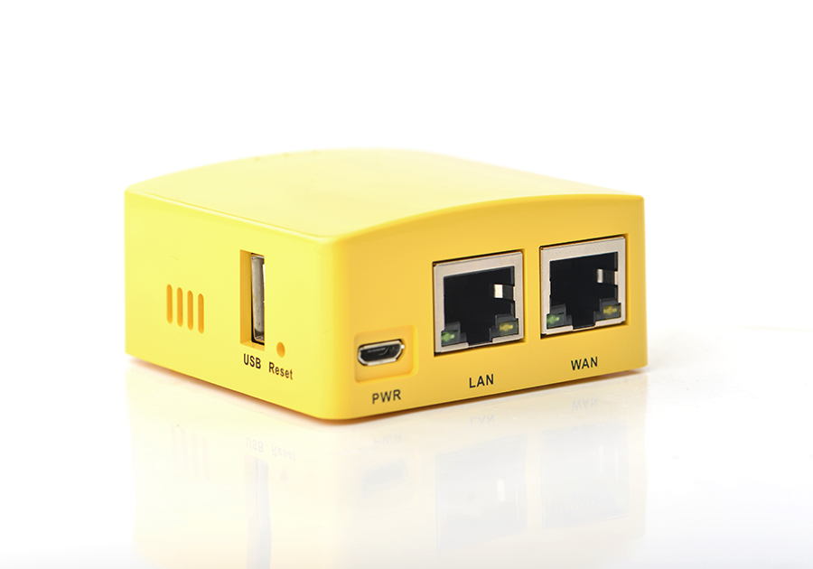
1x “true” Gigabit Ethernet (WAN)
1x “USB 2.0” Gigabit Ethernet (LAN) up to around 330 Mbps
802.11b/g/n WiFi 4 with IPX-I antenna connector
USB – 1x USB Type-A host port, 1x micro USB port
Debugging – 3-pin 2.54mm pitch header for serial console
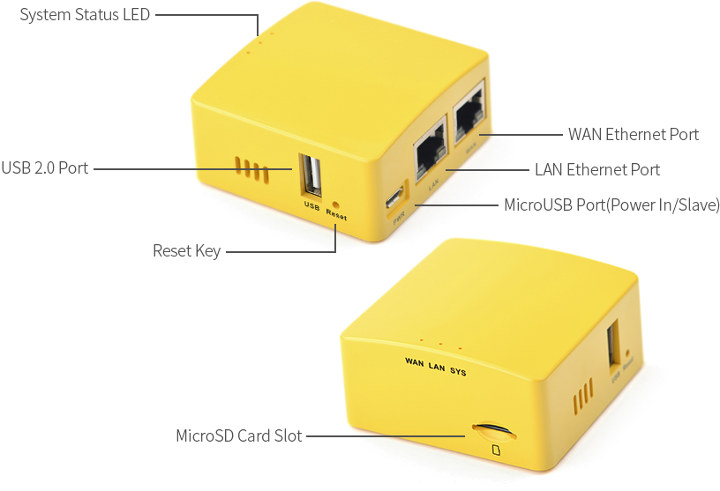
The company does not currently sell the barebone board , and instead, NanoPi R1S is sold as a router with a yellow enclosure (no other colors available) running either FriendlyWrt based on OpenWrt or FriendlyCore based on Ubuntu 18.04, both shipping with Linux 4.14.
You’ll find more technical details and links to the respective firmware files on the Wikis for R1S-H3 and R1S-H5 routers. Cooling is achieved with a heatsink that covers a large part of the board.
NanoPi R1S-H3 router is sold for $19.99, while NanoPi R1S-H3 goes for $3 more, and both are available on the same page on FriendlyELEC shop. I understand the prices include the board, heatsink and enclosure, and you can purchase a 16GB MicroSD card, 5V/3A power supply, and/or micro USB cable as options.
In one of our previous tutorials, we examined the development of a DIY-Geiger Counter showing the efforts of “Instructable” user Prabhat who combined the ESP8266 with a touch screen display to create a truly intuitive version of his Geiger Counter. He recently created an updated version and today’s tutorial will focus on how this new version of the Geiger Counter can be replicated.
The Geiger counter is an instrument used for detecting and measuring ionizing radiation. It is one of the worlds best-known radiation detection instrument as it can be used to detect ionizing radiation such as alpha particles, beta particles, and gamma rays and its is usually used as a handheld radiation survey instrument, warning users when in the region of dangerous ambient radiation levels with an all-too-familiar clicking noise.
While this project retains some of the features from the first version, like the use of the ESP8266 and a touchscreen interface, rather than just implementing the detection of radiation levels like the first version, it combines a Geiger counter, a dosimeter, and a radiation monitoring together in a single package that is 50% less thick, and with loads of new software features! Some of the new features include:
A more intuitive GUI
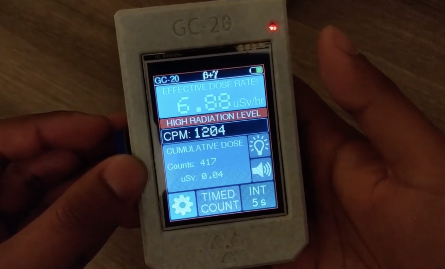
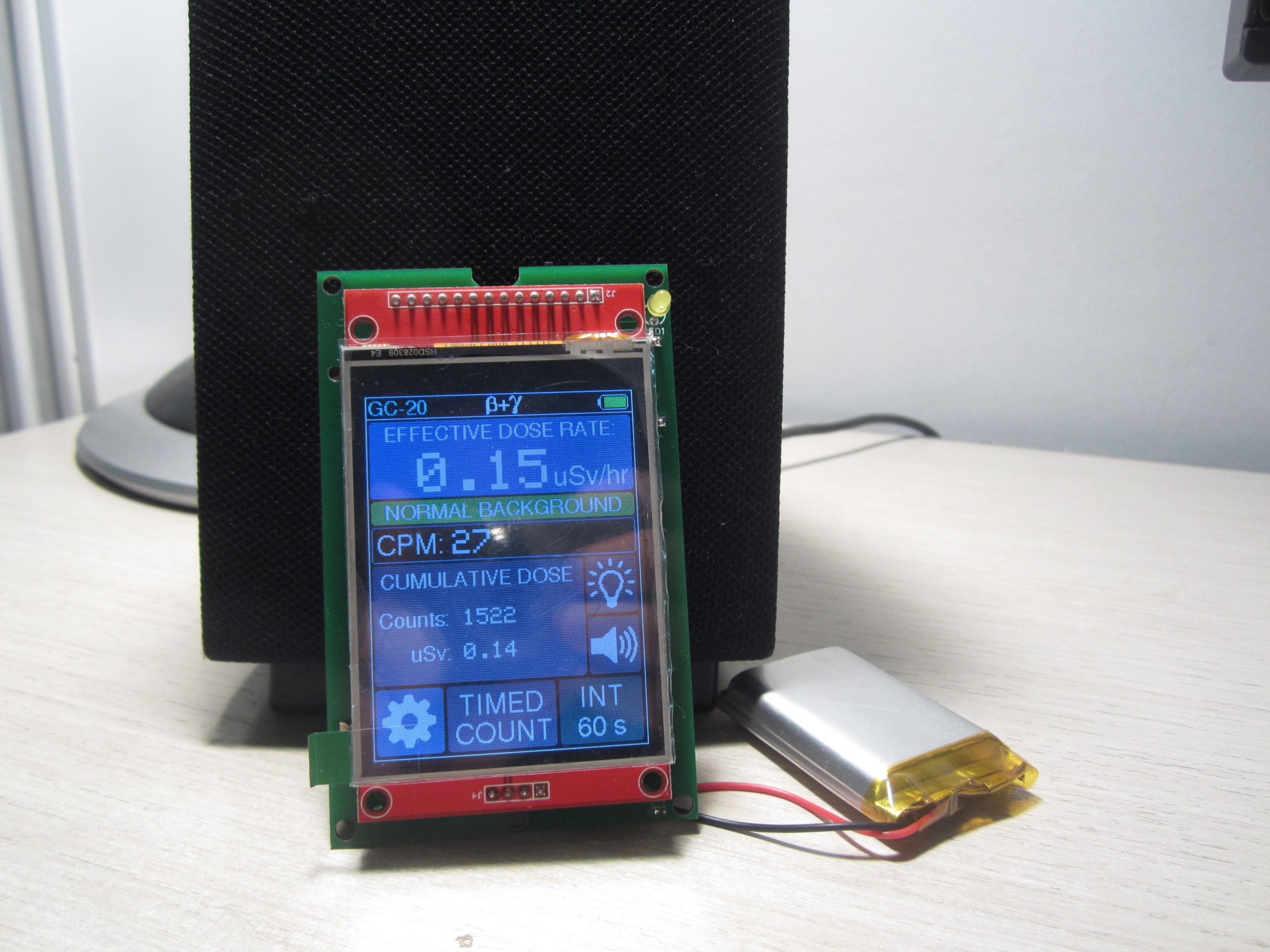
Displays counts per minute, current dose, and accumulated dose on the home screen
Sensitive and reliable SBM-20 Geiger-Muller tube
Variable integration time for averaging dose rate
Timed count mode for measuring low doses
Users can choose between Sieverts and Rems as the units for the displayed dose rate
User-adjustable alert threshold
Adjustable calibration to relate CPM to dose rate for various isotopes
Offline data logging
Post bulk-logged data to a cloud service (ThingSpeak) to graph, analyze and/or save to computer
Monitoring Station mode: device stays connected to WiFi and regularly posts ambient radiation level to ThingSpeak channel
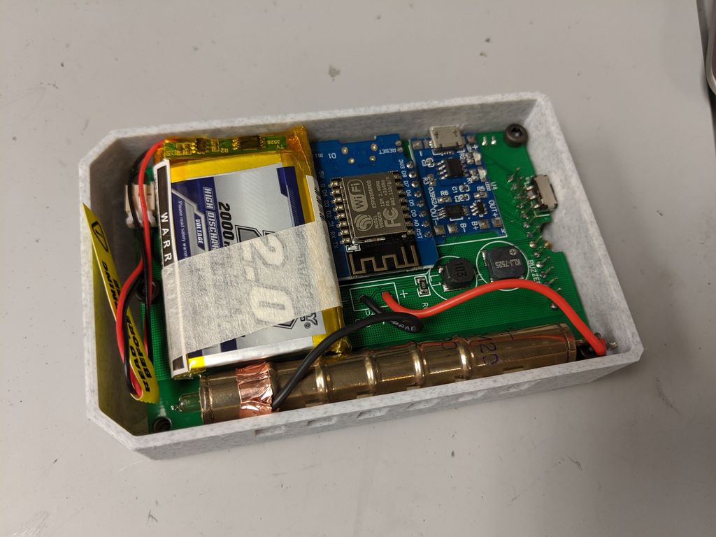
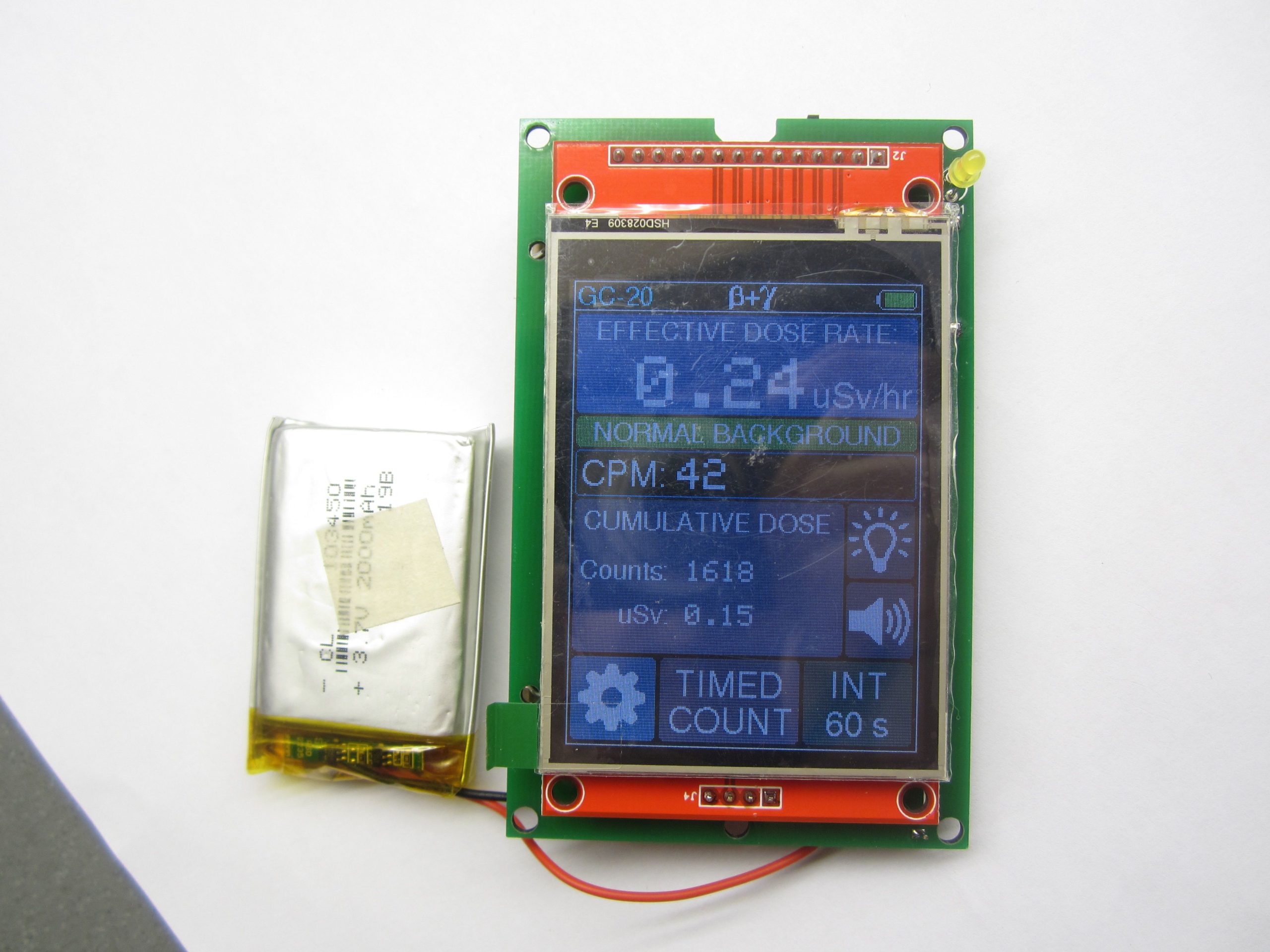
2000 mAh rechargeable LiPo battery with a 16 hour run time and a micro USB charging port
No programming required from the end-user as things like the WiFi setup is handled through the user interface.
While most of these upgrades will not make sense to a non-radiation nerd, the updates take the device to a more powerful level when compared with some of the regular Geiger counter available in the market.
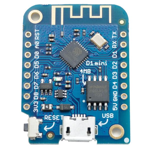
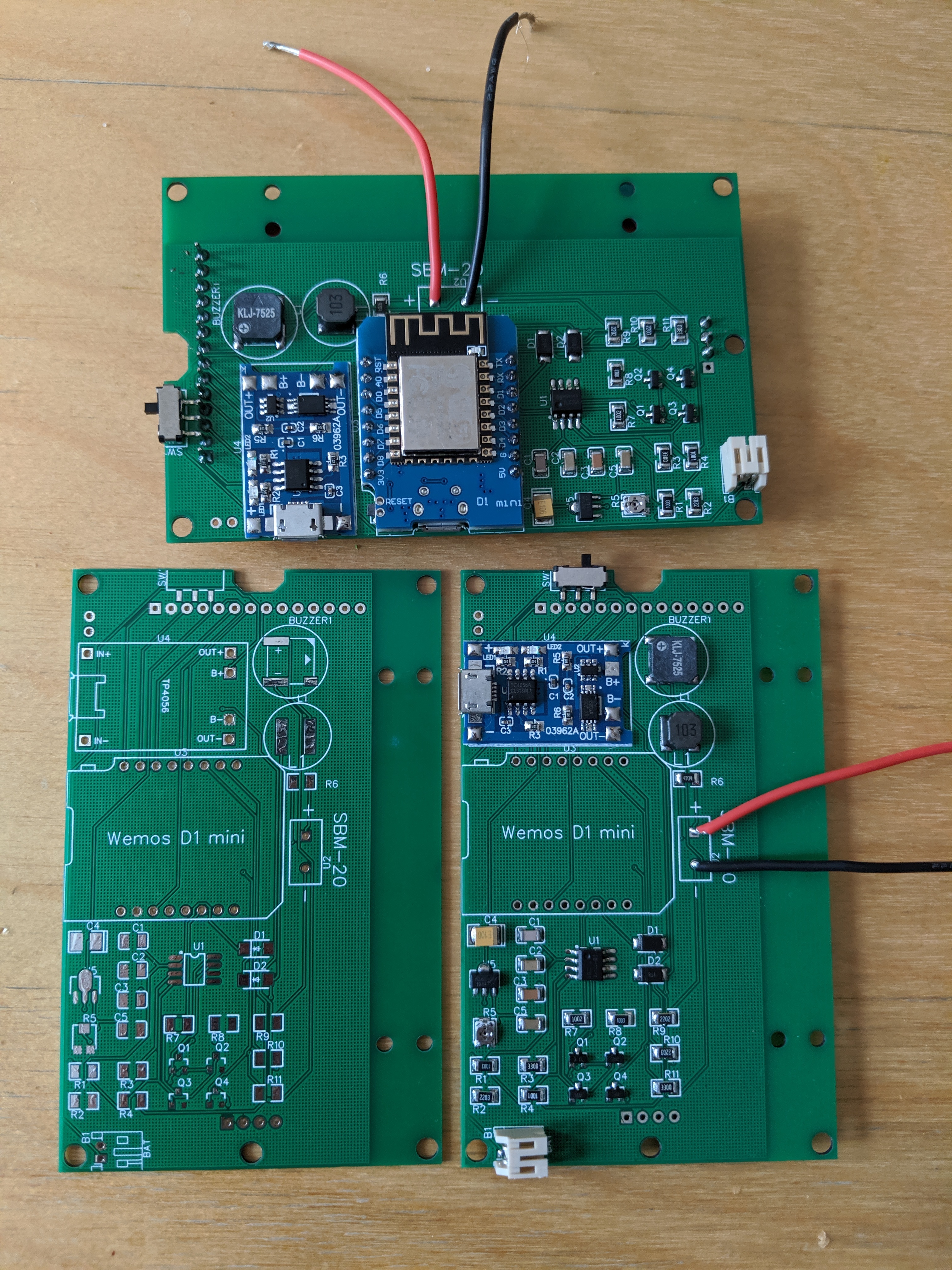
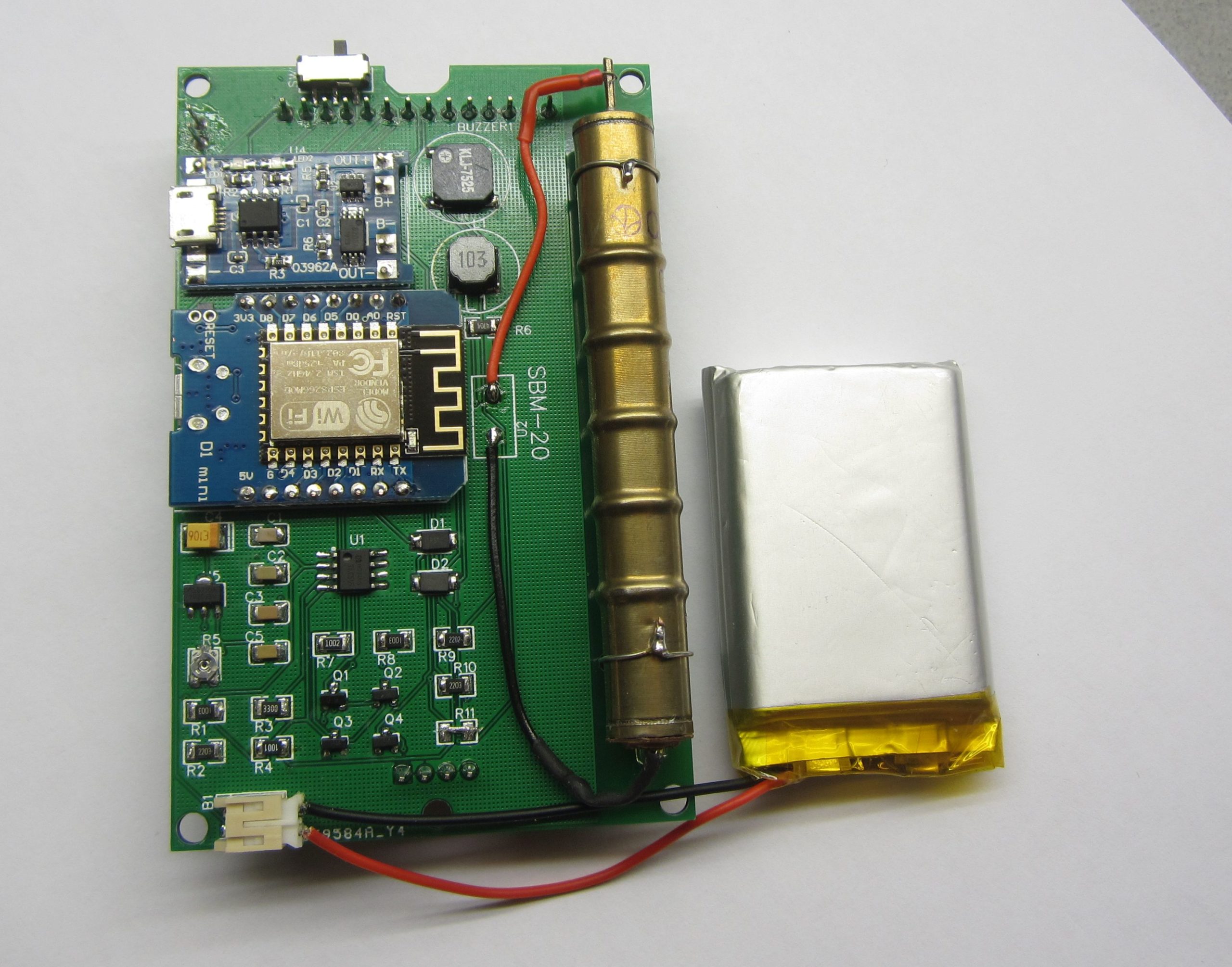
Wemos D1 mini board
The ESP8266 was retained from the previous version, but a Wemos D1 mini was used in place of the NodeMCU to reduce the overall size of the project. The SBM-20 Geiger Muller tube and the 2.8″ SPI touchscreen were also retained. Several other discrete components were used with most of them being of SMD types to make the device compact.
At the end of this tutorial, you would know not only how to replicate this project but how to implement tasks like; building IoT Devices capable of uploading data to Thingspeak, update WiFi details using a GUI without changing the code and so many other fascinating things.
Required Components
The components required in making the full assembly of the project are provided in the list below. The list does not include the discrete components which will be provided in a table so things are not messy.
Minimum anode resistor: 1 MΩ (voltage rating at least 500 V)
Recommended anode resistor: 5.1 MΩ (voltage rating at least 500 V)
Plateau length: at least 100 V
Plateau slope: 0.1% per 1 V
Minimum dead time: 190 μs (at 400V)
SMB-20 Tube Physical specifications
Diameter: 11 mm
Length: 108 mm (+/- 2.5 mm)
Weight: 10 g
Temperature rating: -60 to +70°C
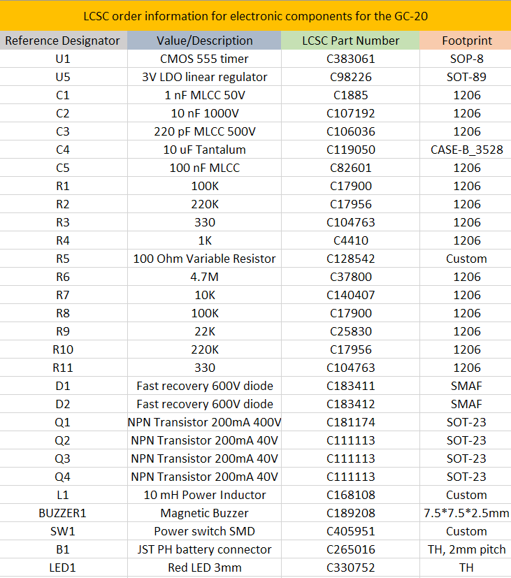
Other discrete components used are provided in the table below and the entire BOM is attached as a .CSV file under the download section.
A table containing discrete components used
All discreet components used for the project were purchased from LCSC.com, so entering the part numbers in the LCSC search bar will show the exact components.
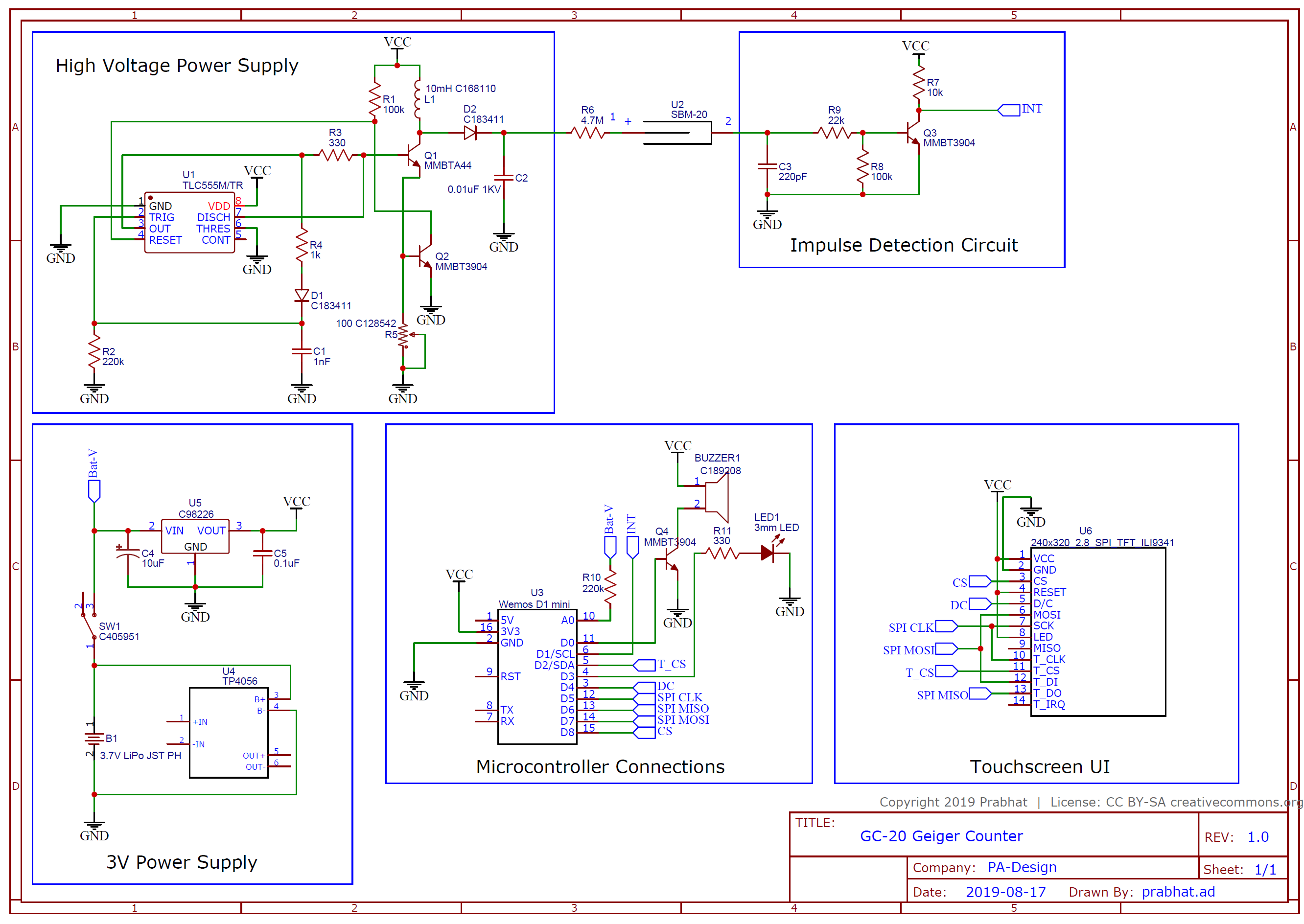
Schematics
The project was implemented using a PCB to make things compact and tidy. As mentioned earlier, most of the electronic parts used are SMD types, and this was done to reduce the size of the device as much as possible. The schematic for the project is designed by Prabhat and it is provided below:
To make it easier for those who may want to make modifications or reproduce the PCB, all of the project files including the schematics and PCB which were developed using Kicad, have been included in the zip file under the download section and can also be downloaded from Prabhat’s GitHub page.
All passive components (resistors, capacitors) were implemented with a 1206 footprint, while the transistors were implemented with SOT-23, LDO in SOT-89, and 555 timers in SOIC-8. Custom footprints were made for the inductor, switch and the buzzer and the required files for them are also zipped with the other files under the download section.
PCB
The PCB after fabrication will look like the image below;
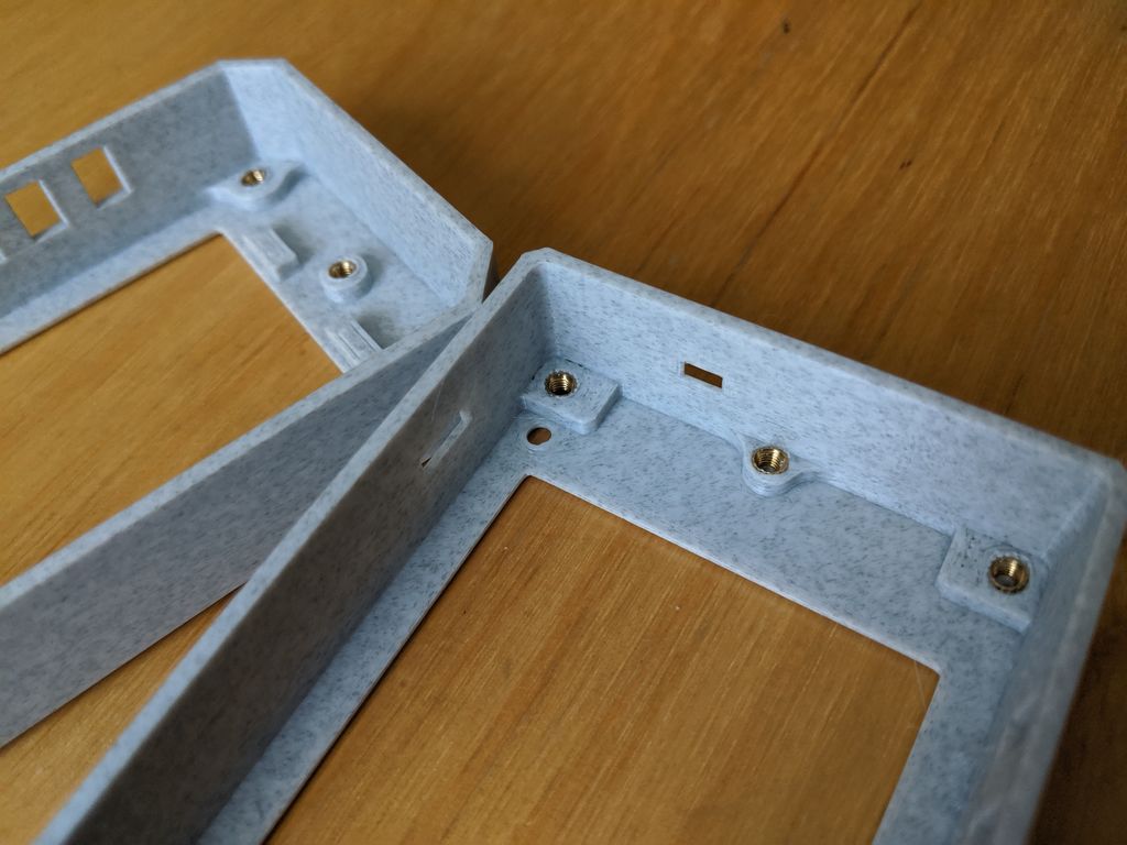
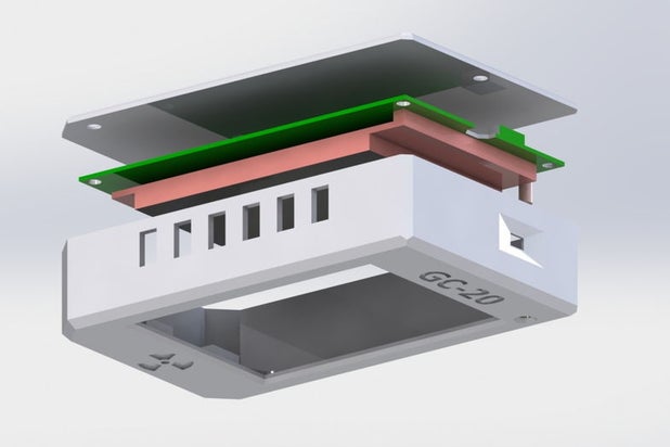
Enclosure Design
A change in the design and placement of components between the two versions means we will also need to create another enclosure for today’s project.
This enclosure was designed to match the new reduced size of the device. It contains fewer parts (just two) compared to the first version and screws are still used in its assembly. Rather than placing the Geiger Muller tube in the top part like the first version, it was placed on the sides of the enclosure to remove the need for additional space at the top of the device.
The .STL files of all parts of the enclosure are attached in the zip file under the download section.
Adjust camera position with the right mouse button.
Double-click to enter the fullscreen mode.
On mobile devices swipe to rotate.
On mobile devices pinch two fingers together or apart to adjust zoom.
On mobile devices 3 finger horizontal swipe performs panning.
On mobile devices 3 finger horizontal swipe performs panning.
Setup Thingspeak
As mentioned during the introduction, this version of the project will have the ability to operate in 3 modes, either as a Datalogger, Monitoring station or as the ordinary Geiger Counter. When used as a data logger or monitoring station, the device is sending it’s data to the cloud and for that reason, Thingspeak was used as the device cloud platform. As such, it is important to create a Thingspeak account and obtain all necessary credentials like; API key and Channel ID as they will be required when the project is being further developed.
Follow the steps below to set up your Thingspeak account;
1. Go to Thingspeak and signup or sign-in if you already have an account.
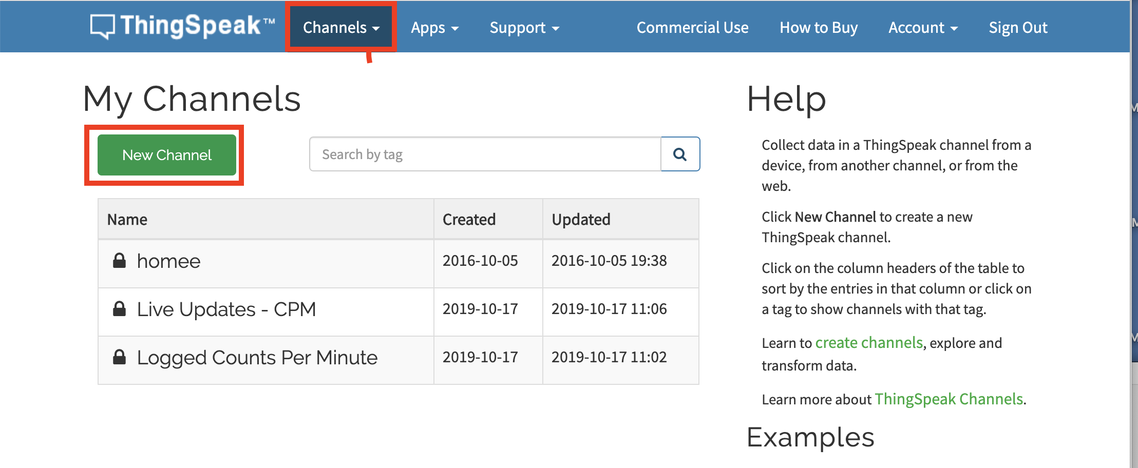
2. After logging in, click on the channels button. This will lead you to the channels page. The channels page provides you with a list of all the channels you have created. Click on the add new channel button to add a new one.
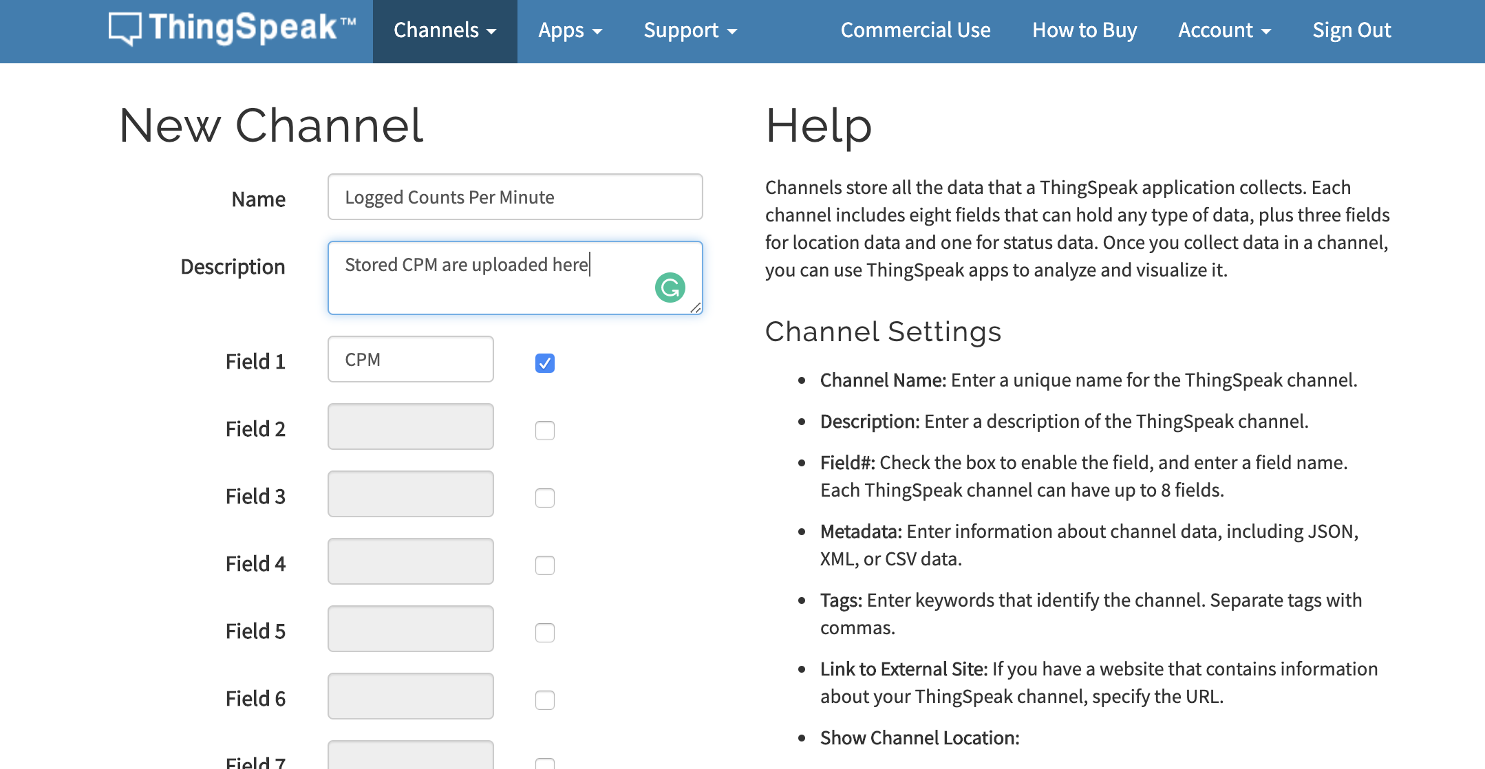
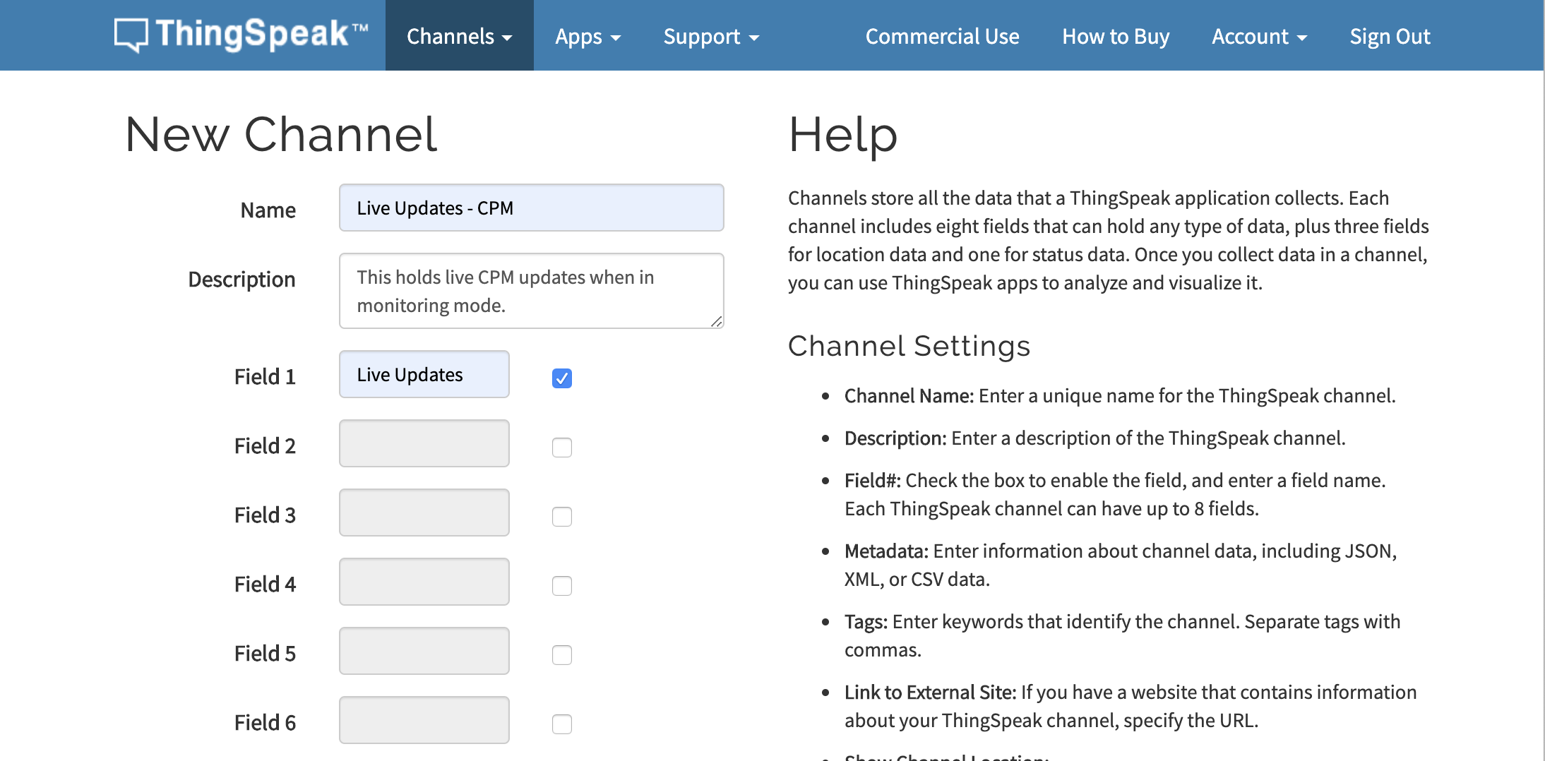
3. This will lead you to a page where you are expected to fill in the details of the channel. Enter the Name, a short description, and fields. For this project, we will create two channels. The first one will hold “Logged counts per minute” data with a field to hold the “CPM”.
4. While the second one will hold “Live Updates of CPM” data with a field called “Live updates“. Click on the OK button after filling the details.
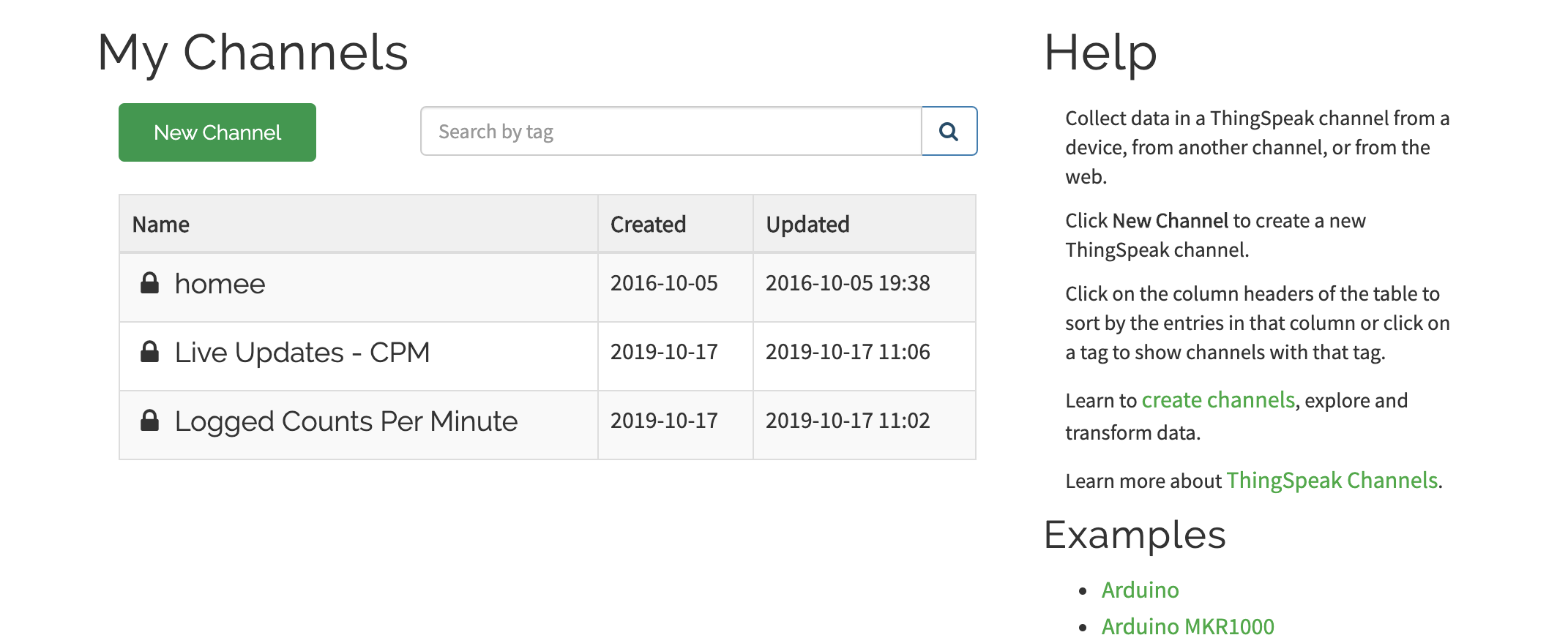
5. The two channels should now be added to your channel list like the image below.
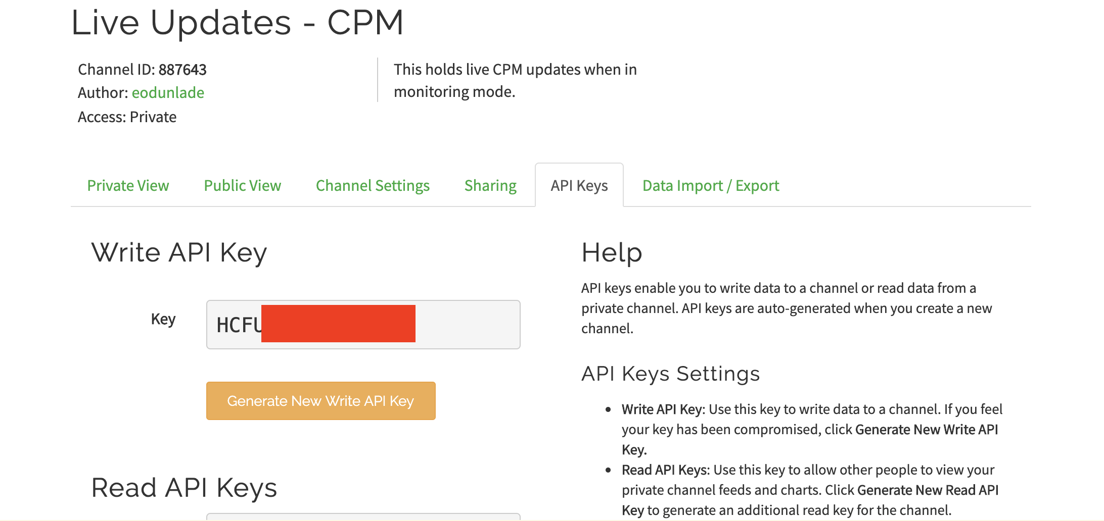
6. By clicking on each of the channels, you will be redirected to the dashboard for that channel where you will see it’s channel ID. Copy the channel ID for both channels as we will use them in our code.
7. On the channel dashboard, also click on API keys. This should show you the API keys to both read and write to the channel. Copy and keep the Write API key since our intention is to write to the channel.
With this done we now have all we need to write the code.
Device Assembly
Follow the steps below to put the device together after the PCB has been assembled.
Start by soldering all SMD components to the Main PCB first, using either a Hot Air Soldering station or reflow oven
Also, Solder the battery charger board to the pads and the through-hole components to the main PCB.
Remove the SD card reader from the LCD display to prevent it from interacting with the Process during data logging.
Solder the LCD board to the PCB AT THE END. You won’t be able to de-solder the D1 Mini after this. Another option is to install the D1 mini using header pins, so there won’t be a need to solder it and it will be possible to remove it at will.
Ensure there are no protruding LEDs and that all components were properly soldered.
Take two pieces of stranded wire and solder one end of the first wire to one end (Anode) of the SBM-20, and connect one end of the second wire to the body of the SBM-2o holding it in place with copper tape. Connect the other end of the two wires to the anode and cathode connections (respectively) on the board. Take care to ensure the polarity is correct.
3D print the case and the cover, and arrange the components inside the case securing the assembled PCB with 3.8mm Screws. Also, place the Geiger tube beside the grill and tape it to prevent it from falling off. Connect all the wires, along with the battery and close up the enclosure using the cover. You should now be ready to go.
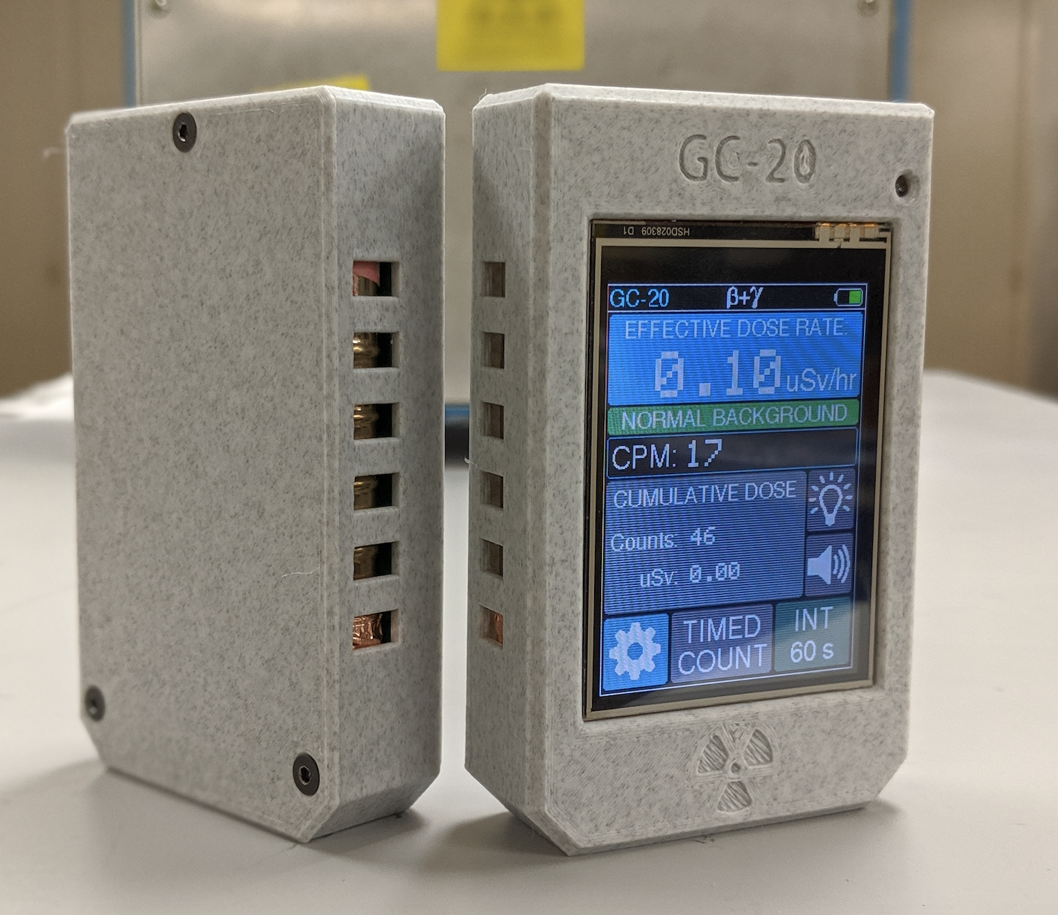
After assembling, the device should look like the image below before the back cover is mounted.
Assembled Geiger Counter
Code
Just like with the previous version, the code for this version is also developed using “PlatformIO IDE“. This means, if you didn’t go through the platformIO.org set up during the last tutorial, you have another chance to get it done now. Follow the tutorial we created a while back on how to Program the Arduino and ESP8266 Boards with Platform.io, to get it sorted.
The sketch for this project is heavily reliant on the Adafruit_ILI9341, the Adafruit GFX, the WiFi Manager library. The ILI9341 library allows us to directly interact with the display as it was used to create the user interface for the display, while the WiFi manager allows users to change the password stored on the device without making any changes to the code, removing the need to edit the code to add WiFi Credentials. Asides these libraries, we will use several other libraries like; the XPT2046_Touchscreen library, the EEPROM library, the SPI library among others. The XPT2046_touchscreen library allows us to use the touchscreen features of the display while the EEPROM library, on the other hand, allows us perform the same tasks it was used for in the first version; to save all the settings including WiFi credentials such that when power is recycled, the data is not lost and users won’t need to supply that information again. All of these libraries can be installed via the Arduino library manager.
The sketch is quite similar to the one for our last tutorial but as usual, I will do a quick explanation of some of the important parts of the code.
We start by declaring the libraries that will be used. In addition to the libraries mentioned above, we will add a couple of font libraries for use in displaying text on the display.
Next, we create an object of the touchscreen library with the CS pin as an argument and then create variables to hold the (4 extremes) calibration points for the touch screen and specify the pins of the Arduino to which the DC and CS pins of the display are connected.
We also create variables to hold the hex values signifying the different colors that we will be using after which we create variables to hold various WiFi/data upload parameters like the password, SSID, API key and channel ID as obtained from Thingspeak, Thingspeak server address among others.
#define BLACK 0x0000
#define BLUE 0x001F
#define RED 0xF800
#define GREEN 0x07E0
#define CYAN 0x07FF
#define MAGENTA 0xF81F
#define YELLOW 0xFFE0
#define WHITE 0xFFFF
#define DOSEBACKGROUND 0x0455

// WiFi variables
unsigned long currentUploadTime;
unsigned long previousUploadTime;
int passwordLength;
int SSIDLength;
int channelIDLength;
int writeAPILength;
char ssid[20];
char password[20];
char channelID[20]; // = "864288";
char channelAPIkey[20]; // = "37SAHQPEQ7FOBC20";
char server[] = "api.thingspeak.com";
int attempts; // number of connection attempts when device starts up in monitoring mode
Next, we create a WiFi through which the device will communicate over the web, and we create an instance of the Adafruit TFT library.
Other variables that will be used for data logging on Thingspeak, monitoring the battery, saving data in the EEPROM, and calculating the dosing units are then created.
const int interruptPin = 5;

long count[61];
long fastCount[6]; // arrays to store running counts
long slowCount[181];
int i = 0;         // array elements
int j = 0;
int k = 0;

int page = 0;

long currentMillis;
long previousMillis;
unsigned long currentMicros;
unsigned long previousMicros;

unsigned long averageCount;
unsigned long currentCount;  // incremented by interrupt
unsigned long previousCount; // to activate buzzer and LED
unsigned long cumulativeCount;
float doseRate;
float totalDose;
char dose[5];
int doseLevel;               // determines home screen warning signs
int previousDoseLevel;

bool ledSwitch = 1;
bool buzzerSwitch = 1;
bool wasTouched;
int integrationMode = 0; // 0 = medium, 1 = fast, 2 == slow;

bool doseUnits = 0; // 0 = Sievert, 1 = Rem
unsigned int alarmThreshold = 5;
unsigned int conversionFactor = 175;

int x, y; // touch points

// Battery indicator variables
int batteryInput;
int batteryPercent;
int batteryMapped = 212;       // pixel location of battery icon
int batteryUpdateCounter = 29;

// EEPROM variables
const int saveUnits = 0;
const int saveAlertThreshold = 1; // Addresses for storing settings data in the EEPROM
const int saveCalibration = 2;
const int saveDeviceMode = 3;
const int saveLoggingMode = 4;
const int saveSSIDLen = 5;
const int savePWLen = 6;
const int saveIDLen = 7;
const int saveAPILen = 8;

// Data Logging variables
int addr = 200;                 // starting address for data logging
char jsonBuffer[14000] = "[";
char data[14500] = "{\"write_api_key\":\"";
unsigned long currentLogTime;
unsigned long previousLogTime;


// Timed Count Variables:
int interval = 5;
unsigned long intervalMillis;
unsigned long startMillis;
unsigned long elapsedTime;
int progress;
float cpm;
bool completed = 0;
int intervalSize; // stores how many digits are in the interval

// Logging variables
bool isLogging;

bool deviceMode;

// interrupt routine declaration
void ICACHE_RAM_ATTR isr();

unsigned int previousIntMicros;              // timers to limit count increment rate in the ISR
Next, we declare all the functions that we will use. It is important to note that this may not be necessary but it just prevents errors that may be experienced with certain C/C++ compilers.
With that done, we then move to the void setup() function.
We start the void setup() function by initializing the serial monitor setting our baud rate to 38400. Feel free to set this to whatever you want, only ensure the serial monitor is set to the same baud rate.
void setup()
{
  Serial.begin(38400);
We then initialize the touchscreen(ts) and the TFT using the begin command and we set the rotation to an orientation that suits us (2 in this case). We also fill the screen with a black color to create a sort of black background.
We follow that up by initializing the EEPROM and initializing a couple of variables including doseUnits, alarmThreshold and conversionFactor , deviceMode, SSIDLength, Channel ID, etc., using data stored on the EEPROM.
The SSIDLength, passwordLength, ChannelIDlength, and writeAPILength are then used as pointers to fetch the SSID, Password, ChannelID, and APIkey, respectively, from the EEPROM.
for (int i = 10; i < 10 + SSIDLength; i++)
  {
    ssid[i - 10] = EEPROM.read(i);
  }
  Serial.println(ssid);

  for (int j = 30; j < 30 + passwordLength; j++)
  {
    password[j - 30] = EEPROM.read(j);
  }
  Serial.println(password);

  for (int k = 50; k < 50 + channelIDLength; k++)
  {
    channelID[k - 50] = EEPROM.read(k);
  }
  Serial.println(channelID);

  for (int l = 70; l < 70 + writeAPILength; l++)
  {
    channelAPIkey[l - 70] = EEPROM.read(l);
  }
  Serial.println(channelAPIkey);
Next, we call the drawHomePage() function to display the home page.
drawHomePage();
To wrap up the void setup(), we check to see if a mode was selected for the device. if no mode was selected, the ESP8266 WiFi features are turned off. But if a mode was selected, the WiFi details are set and the connection progress and status are displayed. Another instance of the drawHomePage is called after the device is successfully connected to the internet.
With that done, we then move to the void setup function.
Next is the void loop function. This is where all the action takes place. The void loop is definitely too long to explain but thanks to the very descriptive variable names that were used, it should be easy to follow. The basic idea is to monitor the dose adjusted parameter which is influenced by the dose rate which is in turn by the activities taking place in the GM tube. When the dose level attains a particular threshold, it triggers the alarm and displays the current critical level of radiation being experienced. There is also a part of the void loop code that creates a JSON file with the readings obtained from the device and uploads it to Thingspeak either at regular intervals or whenever WiFi/internet access is available. Other code snippets in the void loop function are related to displaying data and maintaining the good UI on the display.
Due to its bulkiness, the complete code for the project is attached along with other resources under the download section.
Programming
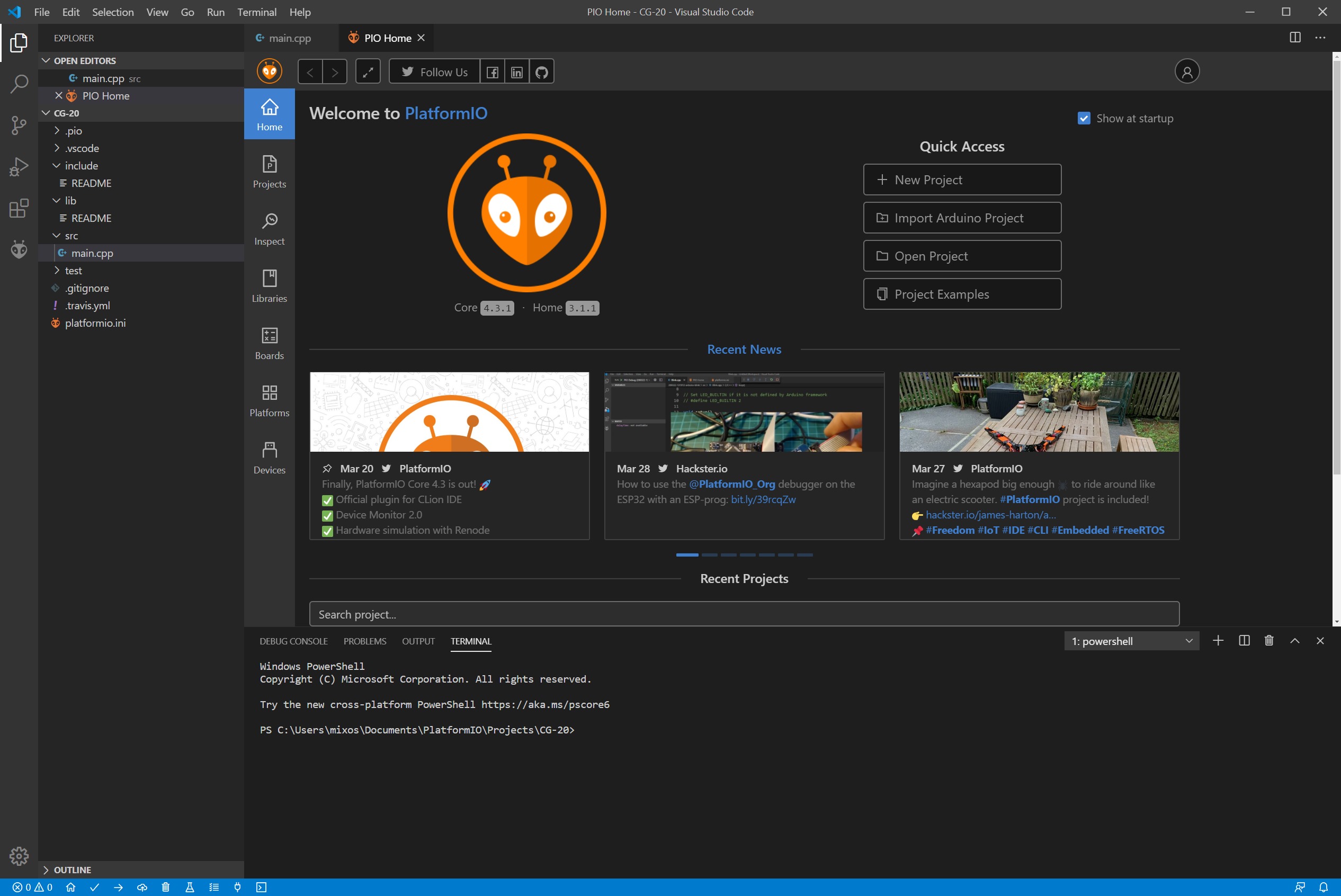
Compiling and upload of the code are done using the PlatformIO IDE as mentioned above. This is a new generation toolset for embedded C/C++ development that you need to install to use the code above. You will need first to download and install the Microsoft’s Visual Studio Code as PlatformIO IDE is built on top of it. To do so follow the short instructions here. Then re-launch the Visual Studio Code to apply the changes. You will now see the PlarformIO extension active as in the screen below:
PlarformIO installed on Microsoft Visual Studio Code
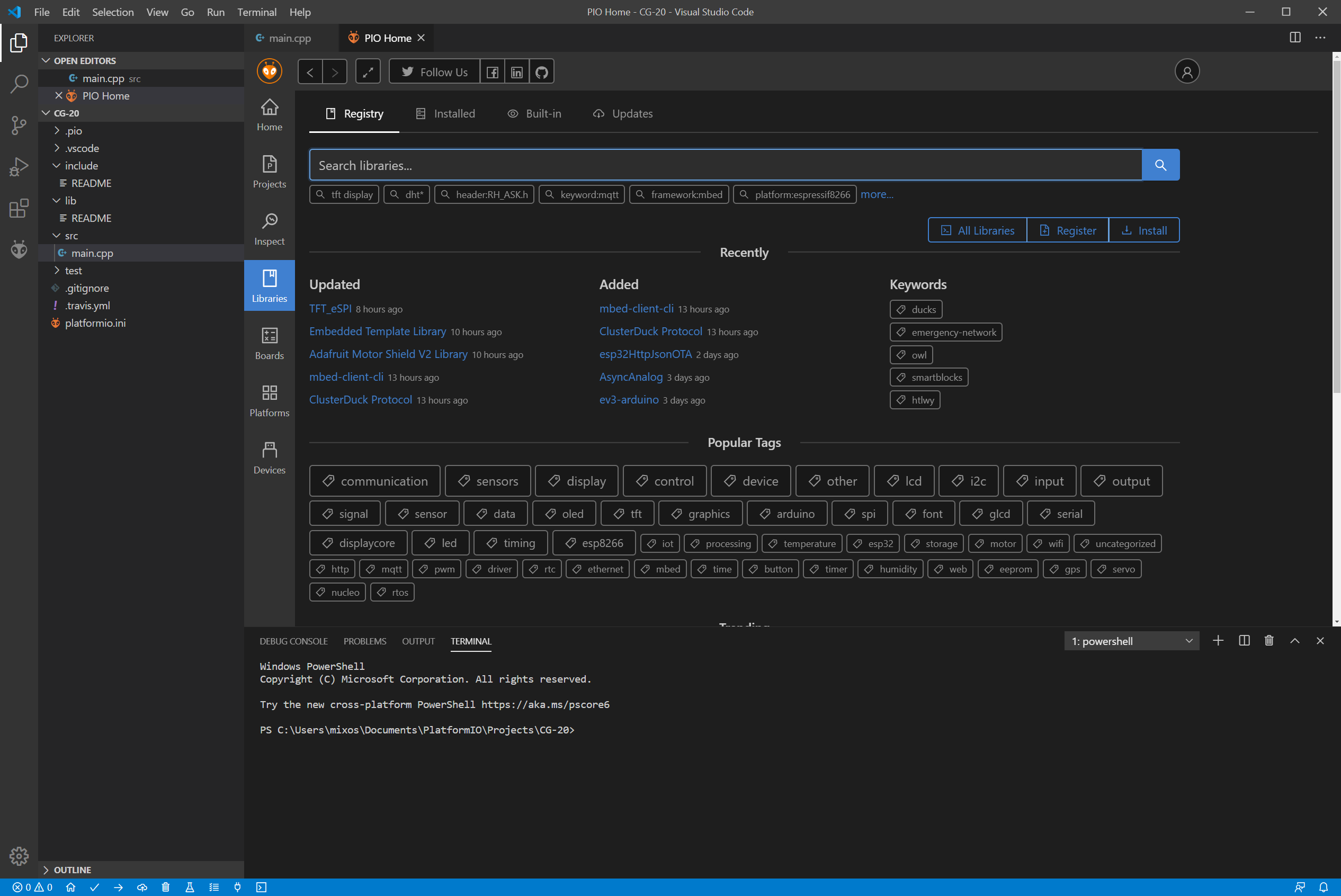
Next click “New Project” -> Add a project name -> Select board: WeMos D1 mini Lite -> Framework: Arduino -> Finish. You will then see a list of directories and files on the left. Select the main.cpp and paste the code found above in the editor. Now it’s time to compile the code and check if everything is fine. Before you do I would advise adding: #include <Wire.h> library in the list of headers as this is needed during compiling. Also, be sure to install the necessary libraries from the library manager:
PlatformIO Library Manager
The libraries needed are:
Adafruit GFX Library
Adafruit ILI9341
Adafruit TouchScreen
WifiManager
XPT2046_Touchscreen
In our case, we had to manually download Adafruit_TouchScreen library and place it in the following path:
C:\Users\<your username>\.platformio\lib
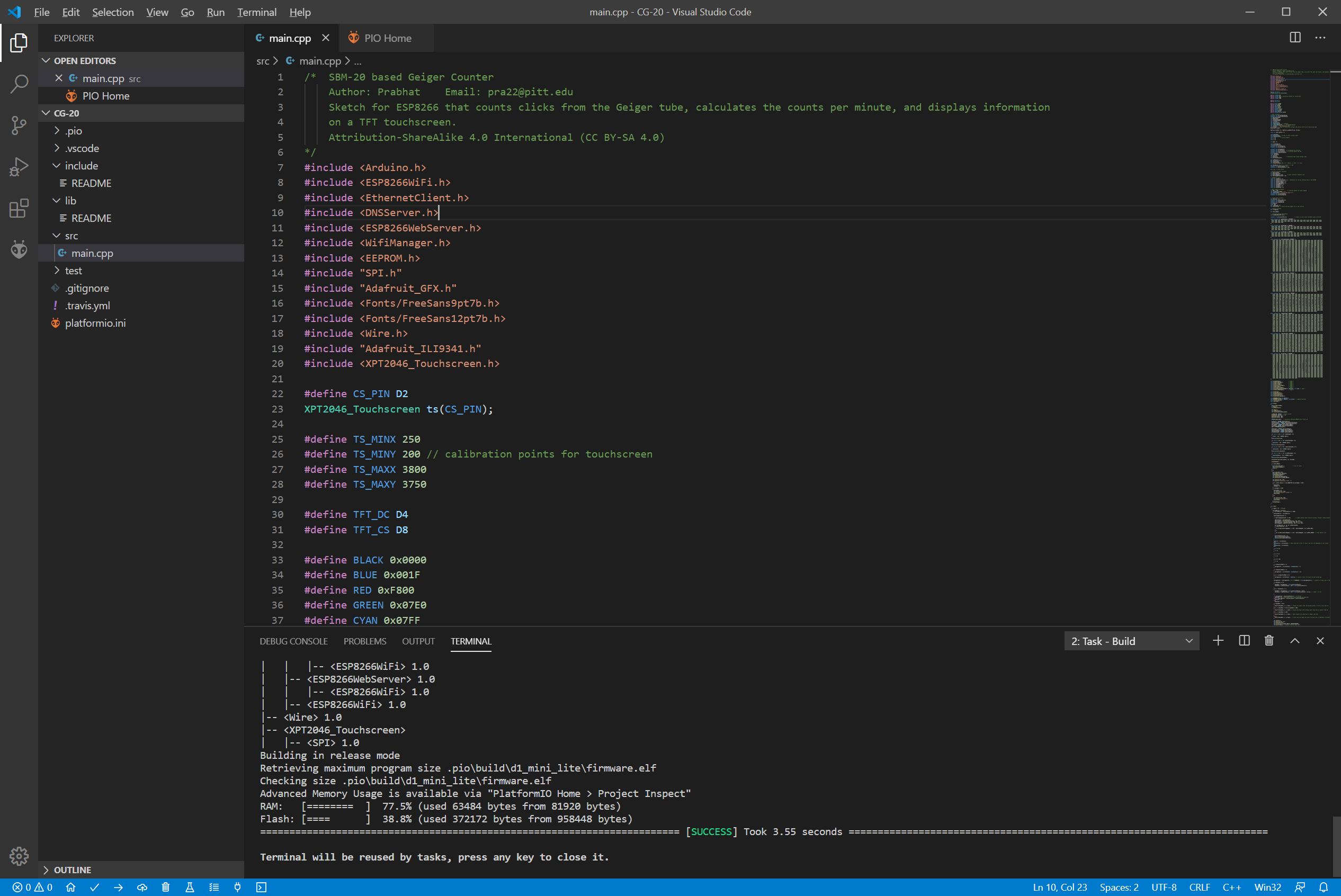
as the library from the build-in manager didn’t work for us. Now it’s time to compile the code using the “Build” button. If everything is fine the code should compile successfully.
Successful Build
Next, we are ready to upload the code to our WeMos D1 board. To do so click the “Upload” button at the bottom of the page. Wait for a few seconds and the code will successfully be uploaded.
Demo
You should now see the screen come up with the home page being displayed as shown in the image below.
Testing the Geiger Counter with various radioactive sources
To test the device, some radiation sources were placed next to it and it was detected as shown in the video below:
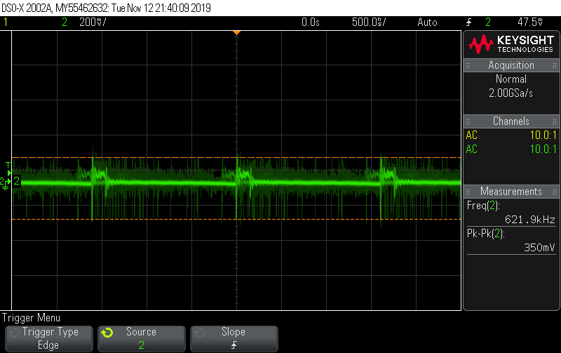
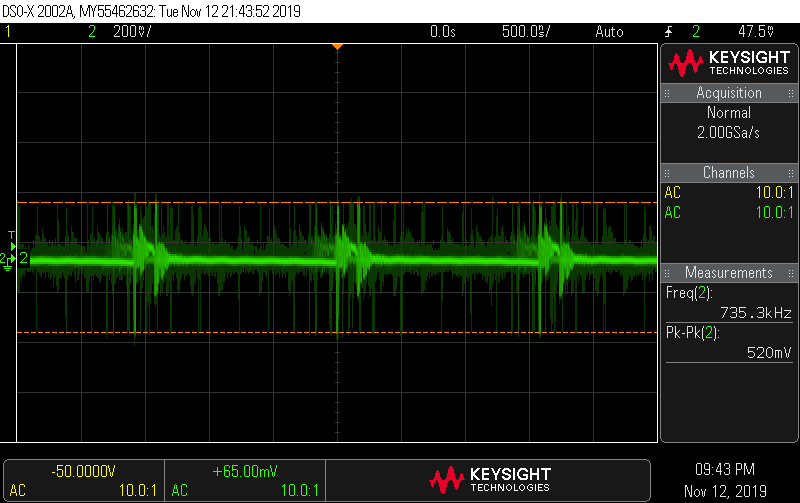
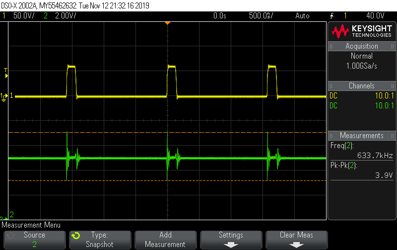
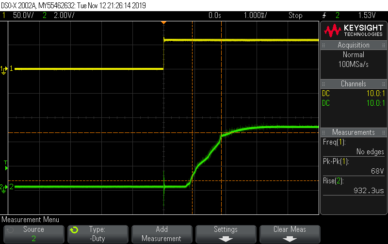
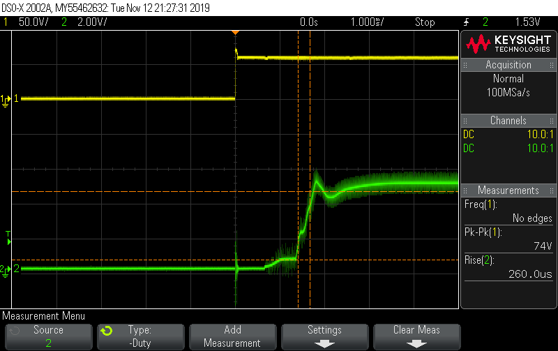
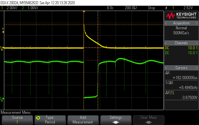
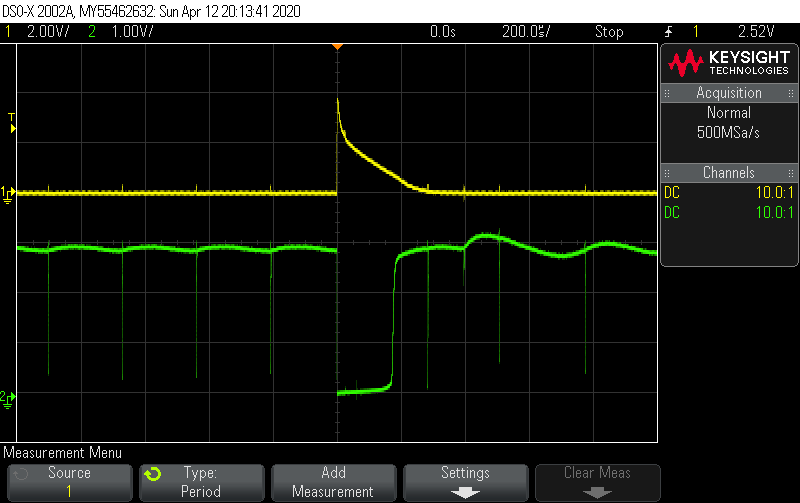
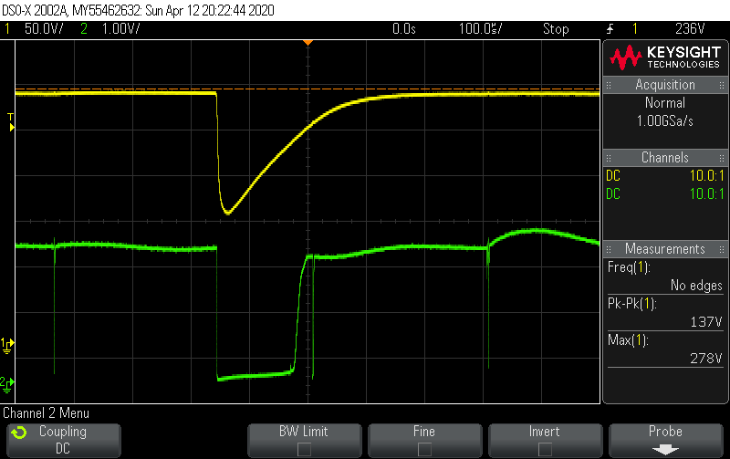
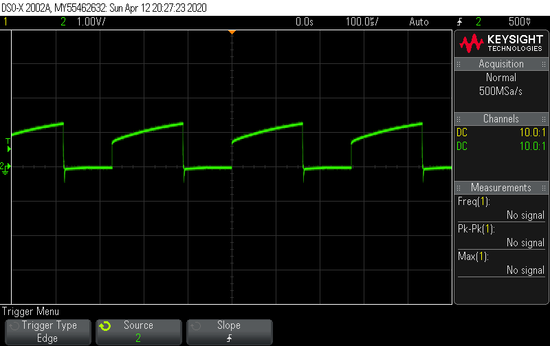
Oscilloscope Measurements
Yellow: The voltage spike from a γ-photon detection on the cathode of the tube. Green: the INT signal produced from the impulse detection circuit that drives the D1 pin of WeMos D1same as above without the measurement markers for better visibilityYellow: The voltage spike from a γ-photon detection on the anode of the tube (we see the voltage drop from 278V to almost half) Green: the INT signal produced from the impulse detection circuit that drives the D1 pin of WeMos D1The discharge voltage on 555 timer IC pin 6
Improvements
The Geiger Plateau Curve (source wikimedia.org)
While the Geiger counter seems to work fine for detecting hard β and γ photons, we should note that the tube working voltage can go as high as 280Vdc using the above 555 timer oscillator. This voltage is below the recommended operating voltage (350 – 475V) for the SBM-20 tube and seems to operate out of the plateau region (100V length) where the tube’s response is flat. So, we would recommend improving the high voltage power supply to a source that can generate higher voltages. This will help to operate the tube on the manufacture recommended voltage.
Conclusion
The GC-20 comes with several new features that allow users to make several changes to the configuration/setup via the user interface, and to make it easy to follow, Prabhat created a user manual for the device to show how it is used. Going through the manual might also help offer better insight into how the code works.
The improvements and features inculcated into the Geiger counter by Prabhat makes it more desirable compared to the regular ones in the market and this goes to show the power of improvement which DIY can bring to a project.
All project files are attached under the download section and do feel free to reach out to me via the comment section if you had any difficulty replicating the project.
A video demo of the project by Prabhat can be found on Youtube.
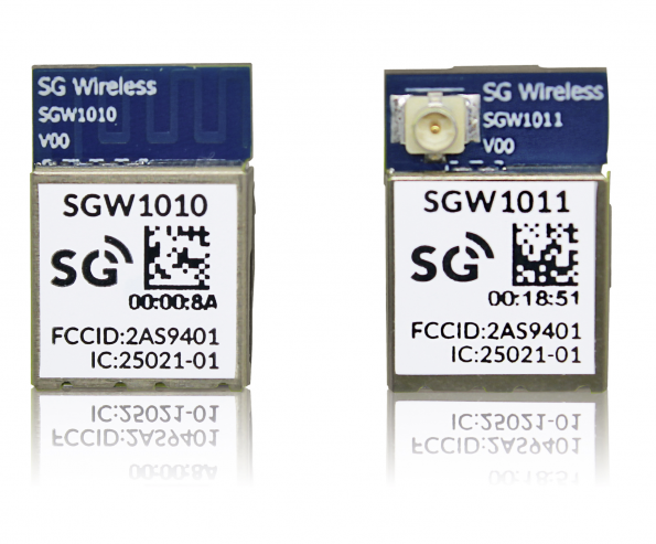
Nordic Semiconductor today announces that SG Wireless has selected Nordic’s nRF52840 Bluetooth® 5/Bluetooth power its SGW1010 and SGW1011 modules. By Wisse Hettinga @ eenewsembedded.com
The modules are designed to provide a complete RF solution for use in a range of IoT applications including connected home, smart city infrastructure, industrial mesh networks, industrial smart lighting, and transport and logistics.
The SGW1010 module provides an embedded PCB trace antenna, while the SGW1011 module offers a u.FL connector for an external antenna. Both modules take advantage of the Nordic SoC’s 64MHz, 32-bit Arm® Cortex® M4 processor with floating point unit (FPU), 2.4GHz multiprotocol radio (supporting Bluetooth 5, ANT™, Thread, Zigbee, IEEE 802.15.4, and proprietary 2.4GHz RF protocol software), 1MB Flash memory and 256kB RAM to provide an advanced, highly flexible, ultra low power multiprotocol solution enabling Bluetooth LE connectivity for portable and extremely low power embedded systems.
The SGW1010 and SGW1011 modules are supplied in a form factor of 10.2 by 15 by 2.1mm and are designed to reduce the engineering efforts and development costs associated with adding Bluetooth 5 to any product, thereby accelerating time to market. Enabled by the nRF52840 SoC’s support for Bluetooth 5, the modules allow OEMs to utilize the Bluetooth 5 Long Range and advertising extension support features in IoT product designs. The integrated nRF52840 SoC provides full Bluetooth 5 support, including 2x on-air raw data bandwidth (2Mbps); 4x range; and 8x broadcasting ability with advertising extensions that increase the advertising packet payload size to 251 bytes. The nRF52840 SoC’s new radio architecture with on-chip PA provides -95dBm RX sensitivity (at 1Mbps in Bluetooth LE mode), a maximum output power of 8dBm, and a total link budget of 103dBm.
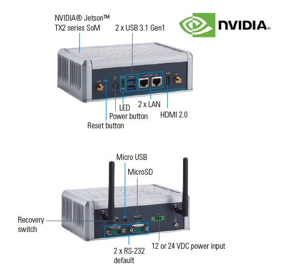
Axiomtek – a world-renowned leader relentlessly devoted in the research, development and manufacture of series of innovative and reliable industrial computer products of high efficiency – is pleased to release AIE500-901-FL, an advanced Artificial Intelligence embedded system for edge AI computing and deep learning applications. The high-performance embedded system employs an NVIDIA Jetson™ TX2 module which has a powerful 64-bit ARM® A57 processor; NVIDIA® Pascal™ GPU with 256 CUDA cores; and 8GB of 128-bit LPDDR4 memory. To withstand the rigors of day-to-day operation, the AIE500-901-FL has an extended operating temperature range of -30°C to +60°C and vibration of up to 3 Grms with its strong construction. This fanless Artificial Intelligence edge system is dedicated to achieving operational excellence, efficiency, reliability in smart manufacturing and intelligent edge applications.
The noticeable edge computing device provides solutions as Edge AI embedded system, specifically designed for video analysis, object classification, computer vision, quality control and more. “Under the ultra-compact enclosure design, the AIE500-901-FL comes with 32GB eMMC onboard and is equipped with one M.2 Key M 2280 SSD slot with PCIe and SATA signal and one Micro SD slot for massive data processing and AI applications. Besides, this reliable embedded system has one full-size PCI Express Mini Card slot and one SIM slot for 3G/4G, GPS, Wi-Fi and Bluetooth connections,” said Annie Fu, a product manager of Product PM Division at Axiomtek.
This outstanding fanless embedded system features a diverse design of I/O interfaces, including one HDMI 2.0 port, two USB 3.1 Gen1 ports, two GbE LAN, two COM ports or two CAN ports, one OTG port and one MicroSD port. It also offers one reset button, one power button, one recovery switch and four SMA-type antenna openings. To meet the industrial and automatic requirements, the reliable edge AI system has a 12 or 24 VDC power input. Moreover, the AIE500-901-FL bundles with NVIDIA® JetPack 4.2.1 to help developers to jump-start their development environment for developing with the NVIDIA Jetson™ platform and minimize what they need to do to develop AI-related applications. It is an ideal Edge solution in AI inference, GPU computing, machine learning, image processing, the artificial intelligence of things and other extended fields.
Advanced Features:
NVIDIA® Jetson™ TX2 with Pascal™, 256 CUDA cores GPU
High performance edge AI computing performance for GPU-accelerated processing
Ideal for intelligent edge applications, machine learning and computer vision
One full-size PCI Express Mini Card slot and one SIM slot
Supports M2. PCIe & SATA SSD and MicroSD slot
Supports 2 USB 3.1 Gen 1 and 2 COM or 2 CAN
Wide operating temperature range from -30°C to +60°C and vibration of up to 3Grms
JetPack 4.2.1 support
Axiomtek’s AIE500-901-FL is now available for purchase. For more product information or customization services, please visit our global website at www.axiomtek.com or contact one of our sales representatives at info@axiomtek.com.tw.
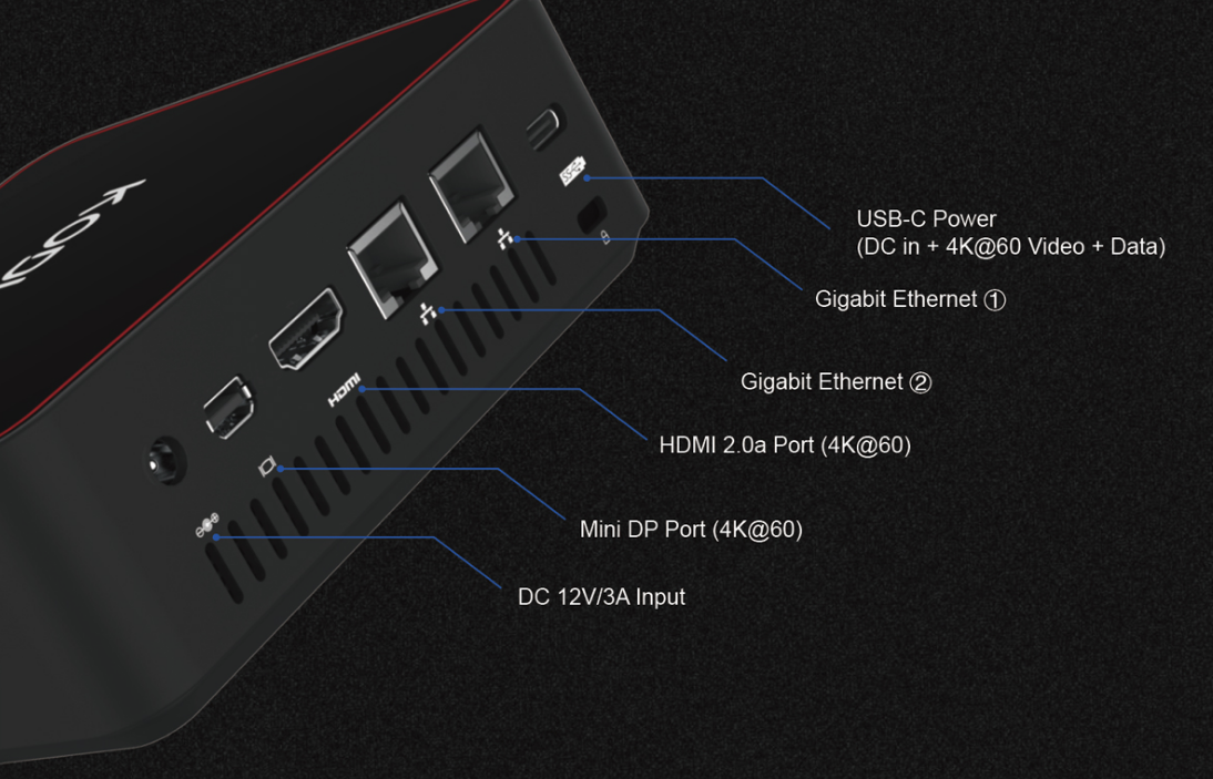
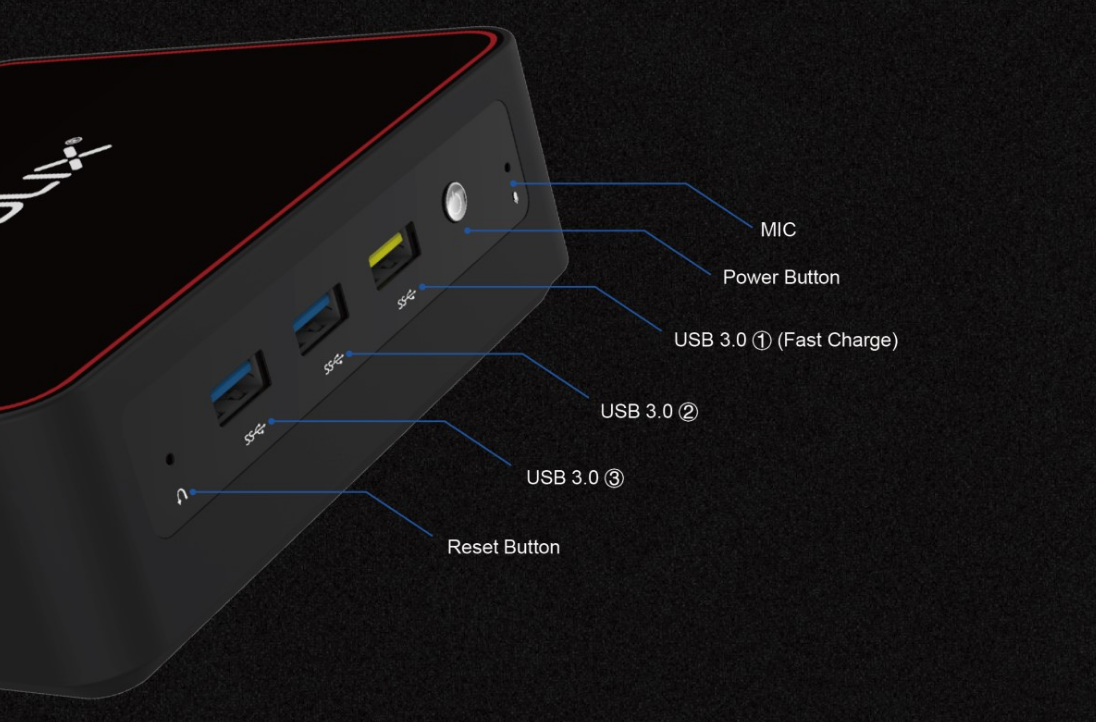
Kodlix computers and accessories are designed for industry and home use. The GK45 is the latest mini-PC built for 4K video options and features, and supports as many as 3 SSDs. The GK45 has 1 x DP, 1 x HDMI, 2 x Ethernet Ports, as well as a USB Type-C display/power port.
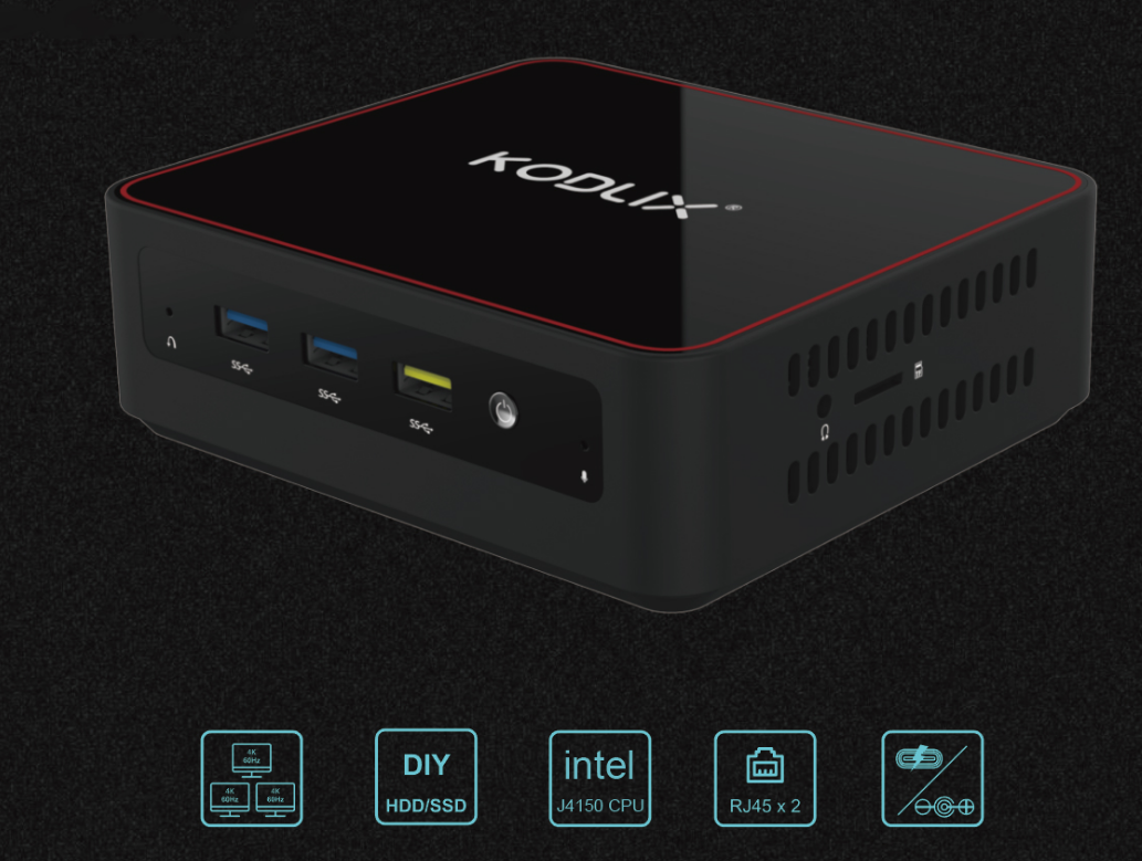
The GK45 runs an Intel Celeron J4105 Gemini Lake processor, that runs at a speed of up to 2.5 GHz. The mini PC can drive up to 3 displays, through mini DP, HDMI 2.0 and USB Type-C, and supports for VP9 10-bit and HEVC 10- bit decoding. All ports that can support a display or monitor or TV up to 4K @ 60Hz.
The GPU is an Intel UHD Graphics 600, with support for video and digital signs, home TV use (larger screens dimensions) medical equipment and education applications.
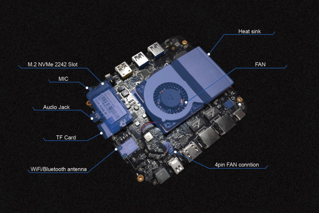
There is support for Windows 10, Linux loaded to the NVMe SSD, for quicker start speeds and loading capabilities. There is 4GB or 8GB LPDDR4 2133 MT/s onboard RAM and a TF Card Reader (SD).
The GK45 has expanded storage capabilities, and can support up to 3 SSDs, in various formats, starting with 64 GB of eMMC (on-board) or M.2 NVMe 2242 128GB SSD, with support for expansion as follows: