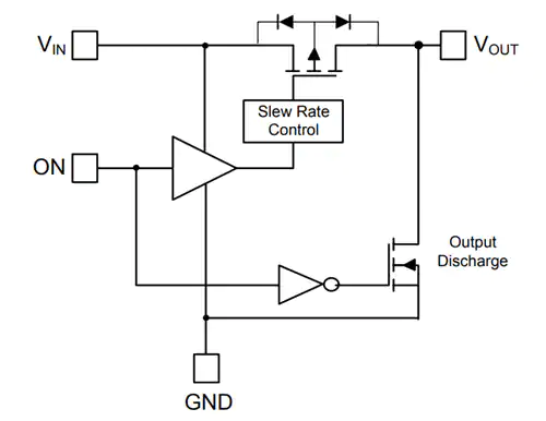
Diodes Incorporated has announced the introduction of the AP22913, a 2A single-channel, slew-rate-controlled load switch with true reverse current blocking for high-side load-switching applications.
Single-channel high-side load switches provide an effective way of applying or removing power to a load, particularly to removable peripherals powered through a USB port.
The AP22913A load switch incorporates true reverse current blocking, which removes the normal body diode unwanted current paths to provide a solution to load switching.
With a load current of up to 2A across a wide operating voltage range, the AP22913 is designed to deliver a typical Rds(on) of 92mΩ at 1.5V and 54mΩ at 5.0V. The firm claims this achieves maximum load current handling capacity with a low forward voltage drop.
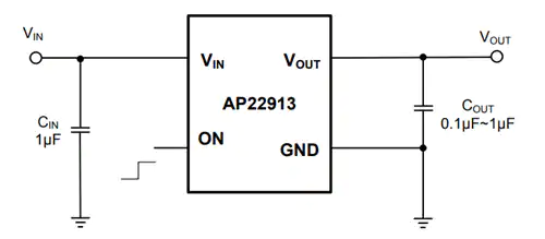
AP22913 typical application
The turn-on slew rate of the device is controlled internally to provide a soft-start feature for sensitive loads while the device also features an active-high enable input to enable load switching. To ensure true reverse current blocking when disabled and in its off state, the vin and vout terminals are completely isolated internally.
Features
1.4V to 5.5V wide input voltage range
Low on-resistance (X1-WLB0909-4):
92mΩ typical @ 1.5V
76mΩ typical @ 1.8V
56mΩ typical @ 3.3V
54mΩ typical @ 5V
Low on-resistance (SOT26):
122mΩ typical @ 1.5V
106mΩ typical @ 1.8V
86mΩ typical @ 3.3V
84mΩ typical @ 5V
High DC current capability up to 2A
Truly Reverse Current Block (TRCB)
Discharging resistor on VOUT when disabled
1µA ultra-low quiescent current
Active-high control pin:
Minimum 1.1V VIH of ON
ESD protection:
2kV human body model
1kV charged device model
Package:
X1-WLB0909-4 with backside laminate
0.9mm x 0.9mm, 0.5mm ball pitch
Standard green SOT26
Totally lead-free and fully RoHS compliant
Halogen and Antimony free
The AP22913 load switch is designed to operate from 1.4-5.5V and consumes a quiescent current of 1µA, making it suited for 1.8V, 2.5V, 3.3V, and 5V systems. With a maximum load current of 2A, the AP22913 is suitable for applications in smart phones, portable, wearable and medical devices, and navigation devices as well as notebooks and ultra-mobile PCs.
The AP22913 is available in options including the AP22913CN4-7, which is housed in the X-WLB0909-4 package, and the AP22913W6-7, which is available in the SOT26 package, both in 1000 unit quantities.
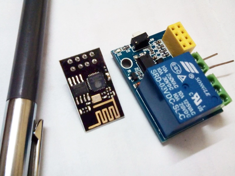
Out of curiosity I ordered a tiny ESP8266 relay switch board from aliexpress.com, for next to nothing. Blissfully unaware, then, of the struggle ahead to make the thing work as advertised. I survived and conquered — here’s the story. By Somnath Bera @ elektormagazine.com
The little gizmo pictured in Figure1 was stated by the vendor(s) to contain an inbuilt switching program, so all I had to do is “use some Android phone to control it”. Sadly, despite several attempts using various Chinese and English-language Android apps, nothing ever happened! Sure, the device gets connected with the Wi-Fi of my PC or laptop as a server and it also allocates the dynamic IP address — but nothing happens after that. No server page etc. opens anywhere! Utterly frustrated, one day I decided to develop and install my own program into its dumb head!
Free Elektor Article: A 3-Dollar Tiny Wi-Fi Switch That Works – [Link]
Researchers at Penn State have developed a fast charging technique to charge a battery in in electric vehicle in just ten minutes. By Nick Flaherty @ www.eenewspower.com
The fast charging technique uses a self-heating battery design to provide faster charging at 60ºC, while cooling the rest of the system to make sure that the battery doesn’t overheat.
“We demonstrated that we can charge an electrical vehicle in ten minutes for a 200 to 300 mile range,” said Chao-Yang Wang, chair of mechanical engineering, professor of chemical engineering and professor of materials science and engineering, and director of the Electrochemical Engine Centre at Penn State. “And we can do this maintaining 2,500 charging cycles, or the equivalent of half a million miles of travel.”
Charging lithium ion batteries at ambient temperatures is slow can can damage battery cells, as the lithium deposits in spikes on the surface of the carbon anode. This lithium plating reduces cell capacity, but also can cause electrical spikes and unsafe battery conditions. Batteries heated above the lithium plating threshold, whether by external or internal heating, do not exhibit lithium plating, so charging at higher temperatures would be more efficient, but long periods of high heat also degrade the batteries.
The self-heating battery uses a thin nickel foil with one end attached to the negative terminal and the other extending outside the cell to create a third terminal. A temperature sensor attached to a switch causes electrons to flow through the nickel foil to complete the circuit. This rapidly heats up the nickel foil through resistance heating and warms the inside of the battery.
“Fast charging is the key to enabling wide spread introduction of electric vehicles,” said Wang. “The 10-minute trend is for the future and is essential for adoption of electric vehicles because it solves the range anxiety problem.”
Wang and his team realized that if the batteries could heat up to 60ºC for only 10 minutes and then rapidly cool to ambient temperatures, lithium spikes would not form and heat degradation of the battery would also not occur. “Taking this battery to the extreme of 60ºC is forbidden in the battery arena,” said Wang. “It is too high and considered a danger to the materials and would shorten battery life drastically.”
The rapid cooling of the battery would be accomplished using the cooling system designed into the car, said Wang.
Adding to the reduction of range anxiety — fear of running out of power with no way or time to recharge — will be, according to Reuters, the establishment of 2,800 charging stations across the U.S., funded by the more than $2 billion penalty paid by Volkswagen after admitting to diesel emissions cheating. These charging stations will be in 500 locations.
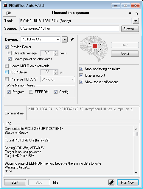
After 2 years in development, the PICKitPlus team is approaching the completion of their new programming tool called PICKitPlus: AutoWatch.
This new tool is designed to facilitate the automatic programming of PIC microcontrollers across a wide range of IDEs and compilers.
PICKitPlus: AutoWatch is software that enables you to simply and automatically program PIC microcontrollers across the very widest range of IDEs and compilers.
You simply select your programmer, select the source HEX file, select a few parameters and you are ready to automatically program your microcontroller. It will automatically detect and work with both the Pickit2, Pickit3 programmers and Xpress and Curiosity Microchip boards.
You select the programmer type, or programmer-on-board type. You manually select the microcontroller, or use automatic detection, then you click “Start”, the software will begin monitoring for changes to the source file and It will automatically program your chosen microcontroller whenever the source HEX file changes. That simple!
There are lots of features like pop programming event notices, you can control the ICSP programming performance, save/load projects and much more.
PICKitPlus: AutoWatch GUI
The new software does not need special integration with the IDE, therefore should work with the vast majority of IDEs. It correctly handles cleaning of IDE folder structures, and PICKitPlus: AutoWatch works with MPLAB-X for Windows and MPLAB-X Cloud.
You may be thinking “I can already do this with the PICKitPlus GUI application”. You can, sort of… but, HEF/SAF is not handled; the GUI will fail when the IDE cleans the folder structure; and it is just generally less robust.
The new tool handles the monitoring and programming procedure in a much more reliable manner and help you do the job in less time.
The PickitPlus team is looking for the first set of users of get the software at a massive discount. Are you willing to install, evaluate the software and provide a short review? If yes then contact the team on pickitplus@pickitplus.co.uk
Be the first to get the software. They are looking for users to review – so, be quick.
Two new 12-inch colour TFT displays from Display Technology Ltd offer superior performance for applications that require consistent readability in challenging conditions or full-HD with high image quality and low power consumption.
The AUO G121EAN01.2 12.1″ WXGA display has outstanding white luminance of 1000Cd/m2 (typical) to display images, graphics, and text clearly under a high level of ambient light. The wide viewing angle, 89° in both axes, ensures consistent visual performance and eases use in equipment such as machine-control panels, ticketing systems, and small displays for exhibition booths, museums, galleries, or similar. The operating ambient-temperature range of -30°C to 85°C allows use in industrial or outdoor settings, and the built-in LED-backlight driver simplifies system integration.
The 12.5” LG LP125WF4-SPQ1 has an ultra-slim 2.85mm profile for use where space is at a premium. With full HD 1920 x 1080 resolution in a 290mm x 170mm outline, the LP125WF4-SPQ1 features the latest embedded DisplayPort (eDP) interface that delivers a combination of high speed and frame rate, low power — drawing just 2.8W (typical) overall — and low EMI. Display Technology can provide a companion LVDS-to-eDP interface board, LVDS2EDP-03, to ease integration with systems that provide only an LVDS output, such as some industrial PCs.
Each of the displays features a 30-way connector that allows simple connection to the host system, requiring only the eDP or LVDS display signals, low-voltage logic power supply, and 12V backlight power supply. Both are in stock now at Display Technology. Please visit the website or call for further information and to place an order.
Data is regarded as the major value proposition of IoT. The ability to receive real time data from different sources, store it and process it into actionable insights to transform and optimize processes either in real time or not is of immense value. This is one of the reasons why device cloud is one of the most important (and sometimes most expensive) part of the architecture of any IoT solution/Project, since the data must be stored in a place where it can be readily accessed for further analysis. For individuals looking to deploy pilots and prototypes of scalable projects on a budget, coughing up the huge sums required for data storage on platforms like Azure, can be quite the burden, and while there are tons of free IoT platforms that can be used, they sometimes have one restriction or the other that makes them not suitable in certain situations. For today’s tutorial, we will look at a cheap/free alternative way to store your data in the cloud. We will look at how you can connect your IoT based devices to Google Sheet so to be able to log data.
IoT: Log Sensor Data to Google Sheets using NodeMCU – [Link]
Data is regarded as the major value proposition of IoT. The ability to receive real time data from different sources, store it and process it into actionable insights to transform and optimize processes either in real time or not is of immense value. This is one of the reasons why device cloud is one of the most important (and sometimes most expensive) part of the architecture of any IoT solution/Project, since the data must be stored in a place where it can be readily accessed for further analysis. For individuals looking to deploy pilots and prototypes of scalable projects on a budget, coughing up the huge sums required for data storage on platforms like Azure, can be quite the burden, and while there are tons of free IoT platforms that can be used, they sometimes have one restriction or the other that makes them not suitable in certain situations. For today’s tutorial, we will look at a cheap/free alternative way to store your data in the cloud. We will look at how you can connect your IoT based devices to Google Sheet so to be able to log data.
Google sheet is most commonly used in place of Microsoft Excel to develop spreadsheet documents. It provides a good way to store or process data in spreadsheet form and it can be integrated with dozens of other services provided by Google like Maps, to create truly innovative solutions. Through APIs and the use of Google script (Gscript), Google made it easy for developers to programmatically fill in data into a google sheet thus making it easy to build solutions using their services and this is what we will use for this tutorial..
As an example to show the use of Google Sheets as the device cloud, we will build a simple temperature and humidity based IoT weather monitor. The device will obtain temperature and humidity from the environment using DHT11 and upload the data over WiFi to a Google Sheet file.
Ready? let’s jump in.
Required Components
The following components are required to build this project;
ESP8266 NodeMCU
DHT11 Temperature and Humidity Sensor
LED
Jumper wires
Bread Board
The nodeMCU is being used because of its popularity and robust WiFi implementation. Any of the other ESP-12e based boards can also be used without much modification to the setup and code.
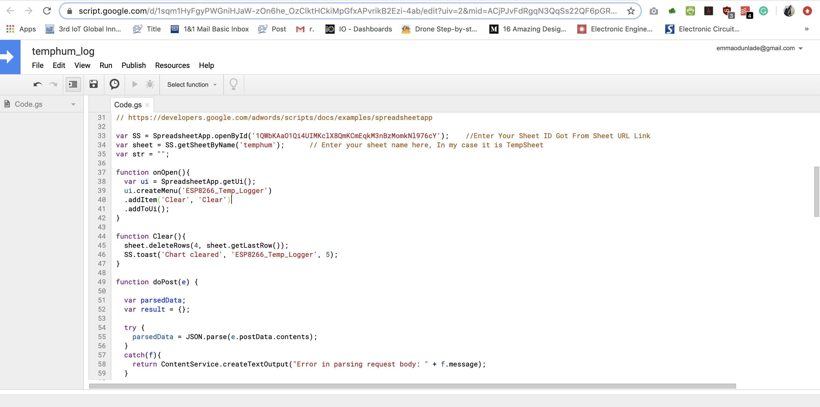
Schematics
The schematics for this project is quite straight forward. We only need to connect the LED and DHT to the Nodemcu as shown in the image below.
Schematics
The pin to pin map of the connection between the NodeMCU and the DHT is also illustrated below to make things clearer.
NodeMCU - DHT
3.3V - VCC
GND -GND
A0 - DO
Go over the connection to ensure everything is as it should be before proceeding to the next section.
Creating and Preparing the Google Sheet.
To send data to a google sheet, we need to first create the sheet and then prepare it to receive data from the device by creating a Gscript (Google Script) to tie the sheet to our device.
Follow the steps below to do this:
1. Point your web browser to docs.google.com.You might need to sign in to your google account or create a new one before you can access the link.
2. When the page opens, click on the menu button and select the Google sheet from the drop-down of applications.
3. The above will launch a new page where you can choose the option of creating a new sheet.
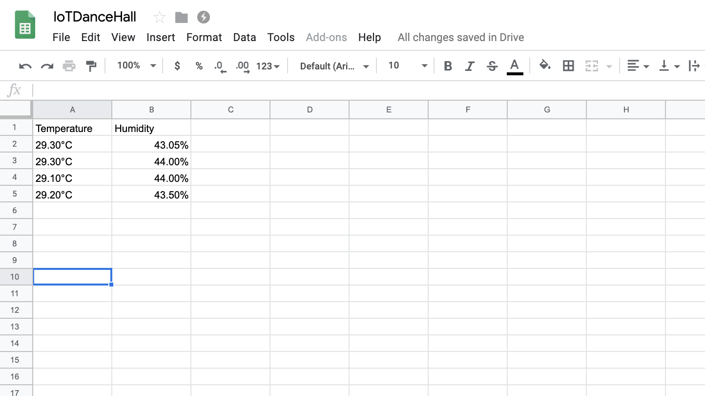
4. When the new Spreadsheet opens, Give it a name (Document title) that is easy to reference. Under every GoogleSheet document you can create multiple sheets, but for this project, we will only use the default sheet 1, also change the sheet name to something that resonates with you.In my case, the document title is IoTDanceHall while the sheet is name temphum.
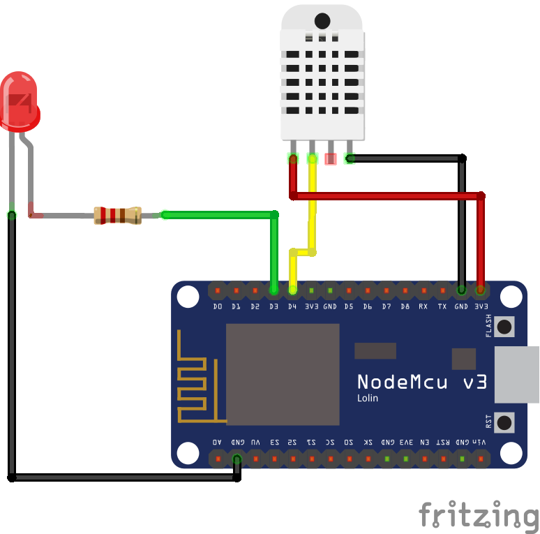
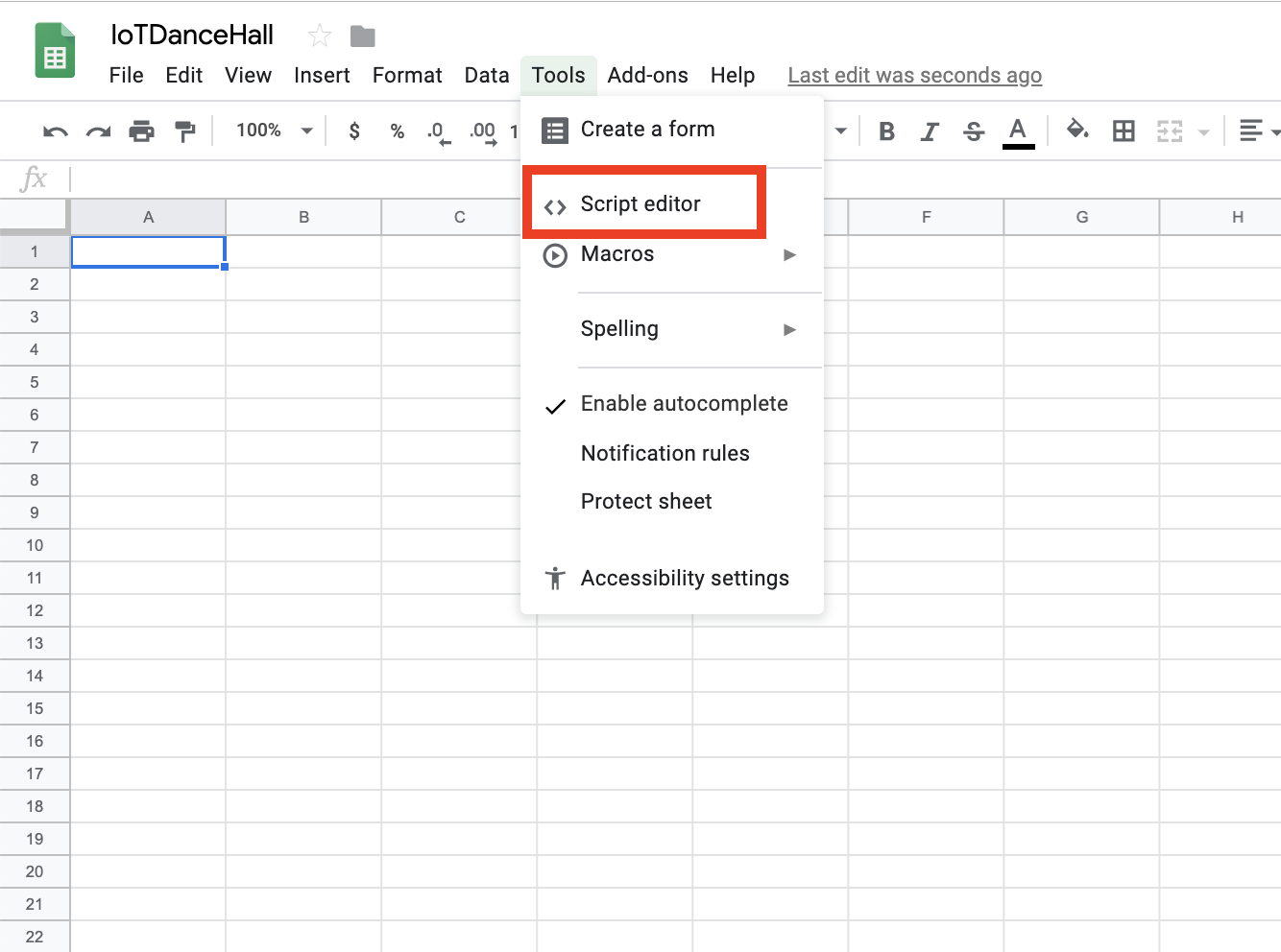
Rename the File and Sheet
5. With the sheet created and the names changed, it is now time to create the google sheet file for the project. Go to Tools on the menu bar and select script editor as shown in the image below.
Launch Script Editor
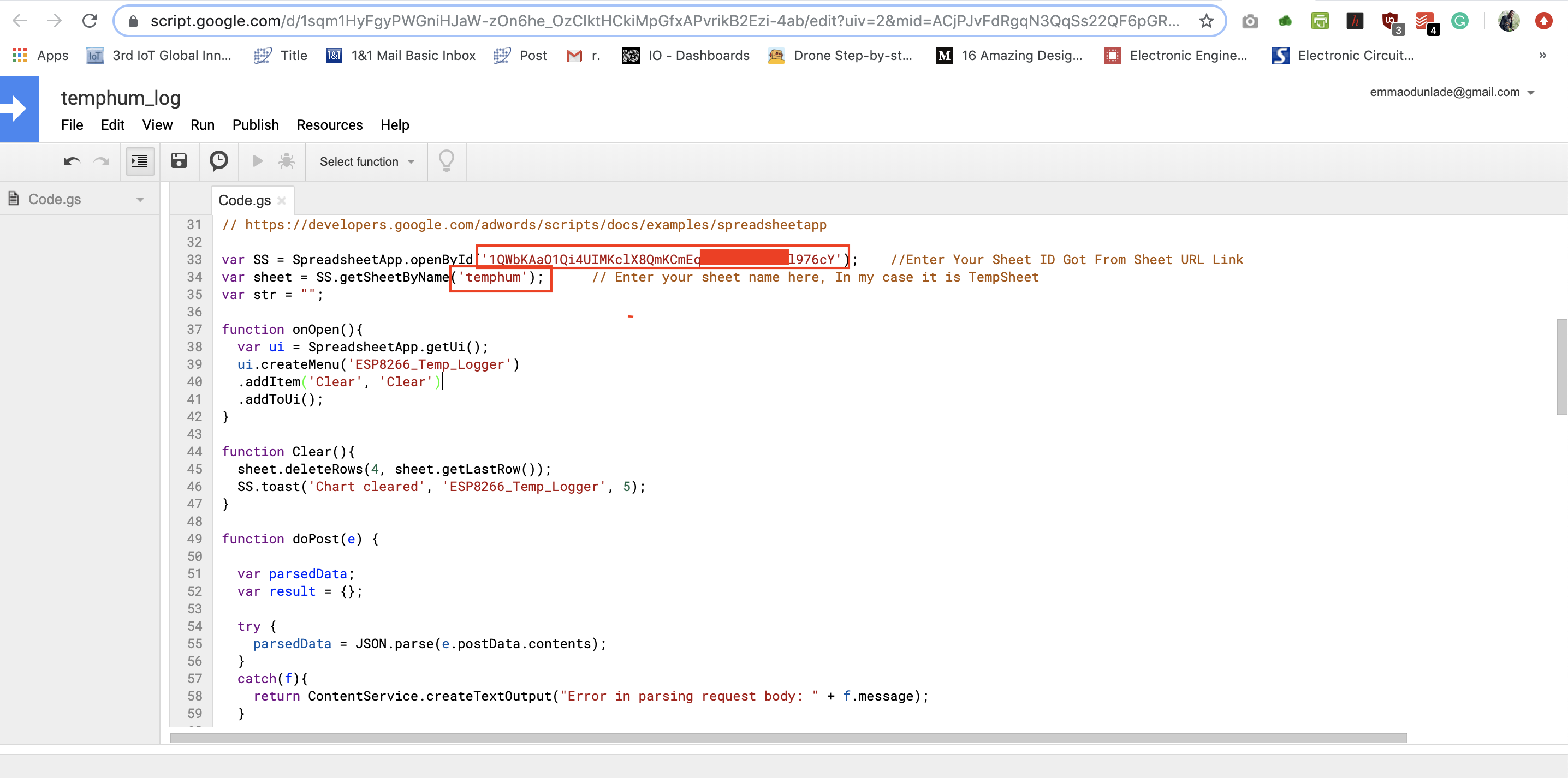
6. It will launch a new tab which will open the Google Script Editor. Rename the Google script file to a name you can relate with. For this tutorial, I will be calling the file “temphum_log“.
7. Next, we will borrow the script developed by Sujay which uses the google calendar to create blanks on a designated google sheet for the data being sent from the device to fill, making it easy to read and write to a GoogleSheet. The script is attached under the download section. Copy the script content and paste in the editor.8. Edit the sheet name and sheet ID in the code to match with your own sheet name (which is “temphum” in my case ) and your own sheet ID.
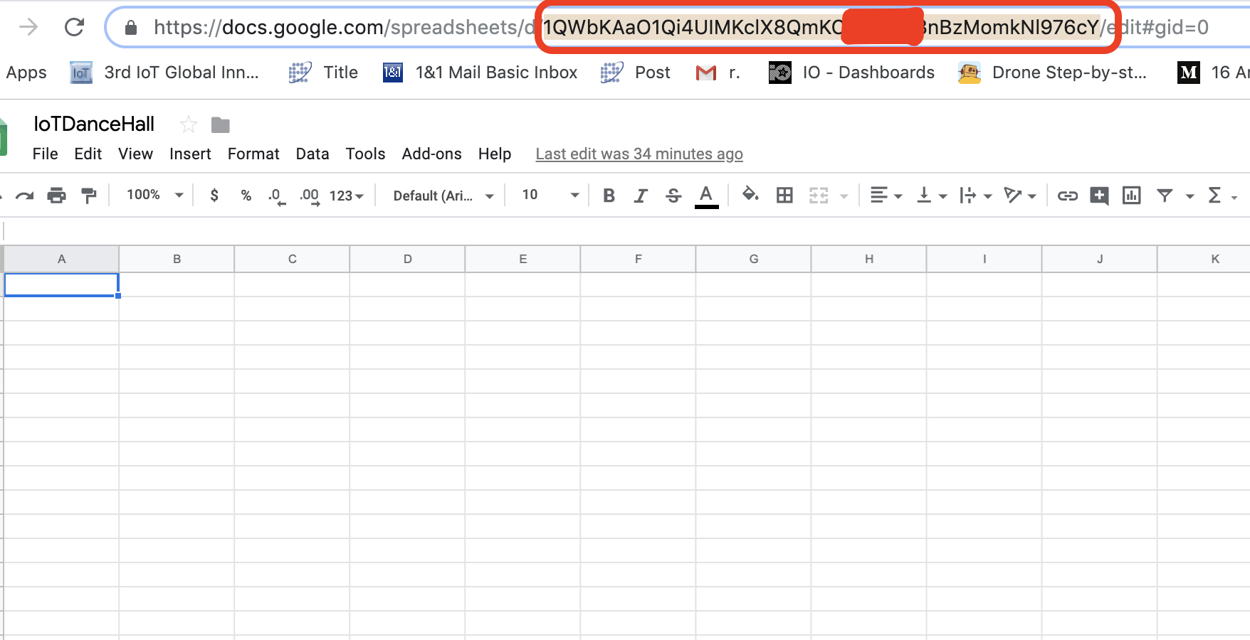
Enter Sheet ID and Name in Script
Your sheet ID is part of your sheet URL. It occupies the position between the backslash after “d” and the one before “edit” highlighted below in the URL
Double-check it before pasting to ensure nothing was omitted as the script will not be able to interact with your sheet if the ID is incorrect. Also Keep this ID safe for future use.
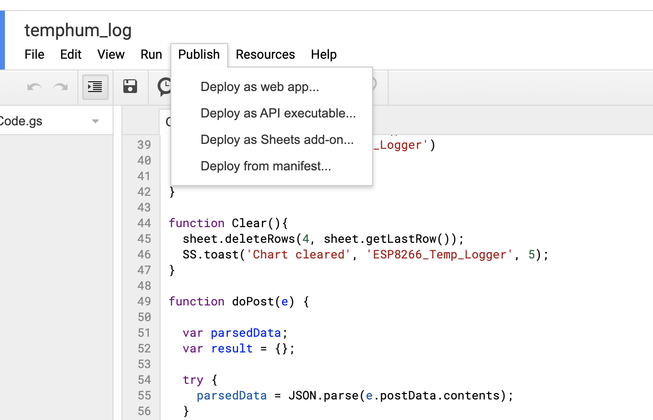
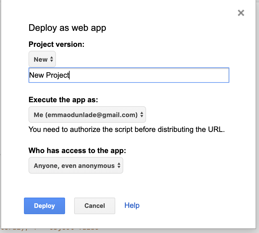
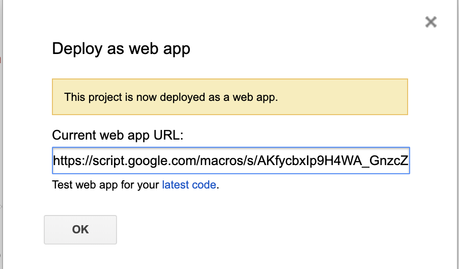
9. With the Gscript editing complete, click on the publish button on the top tool bar and select “deploy as web app” from the drop down.
10. It will launch an interface where you will need to fill a bunch of information. Fill as shown in the image below with the Project version set to new, your email ID selected, and given anyone, even anonymous access to the app. With that done, click on the deploy button.
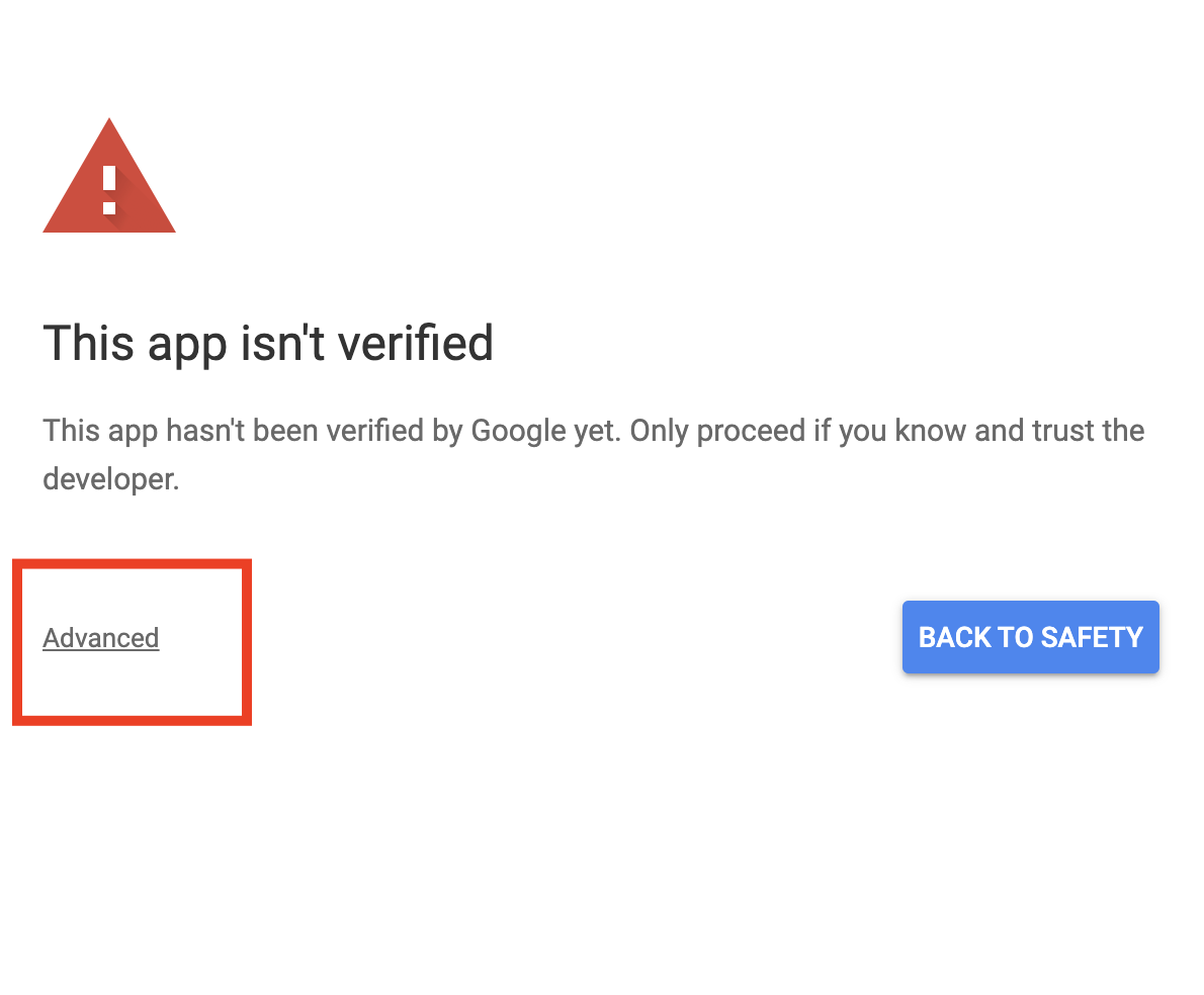
11. Deploying will require that you give the script some permissions. Click on review permissions when prompted. Since the script is not a verified google app, it will throw a warning as shown below. Review this by clicking the advanced button in the image below.
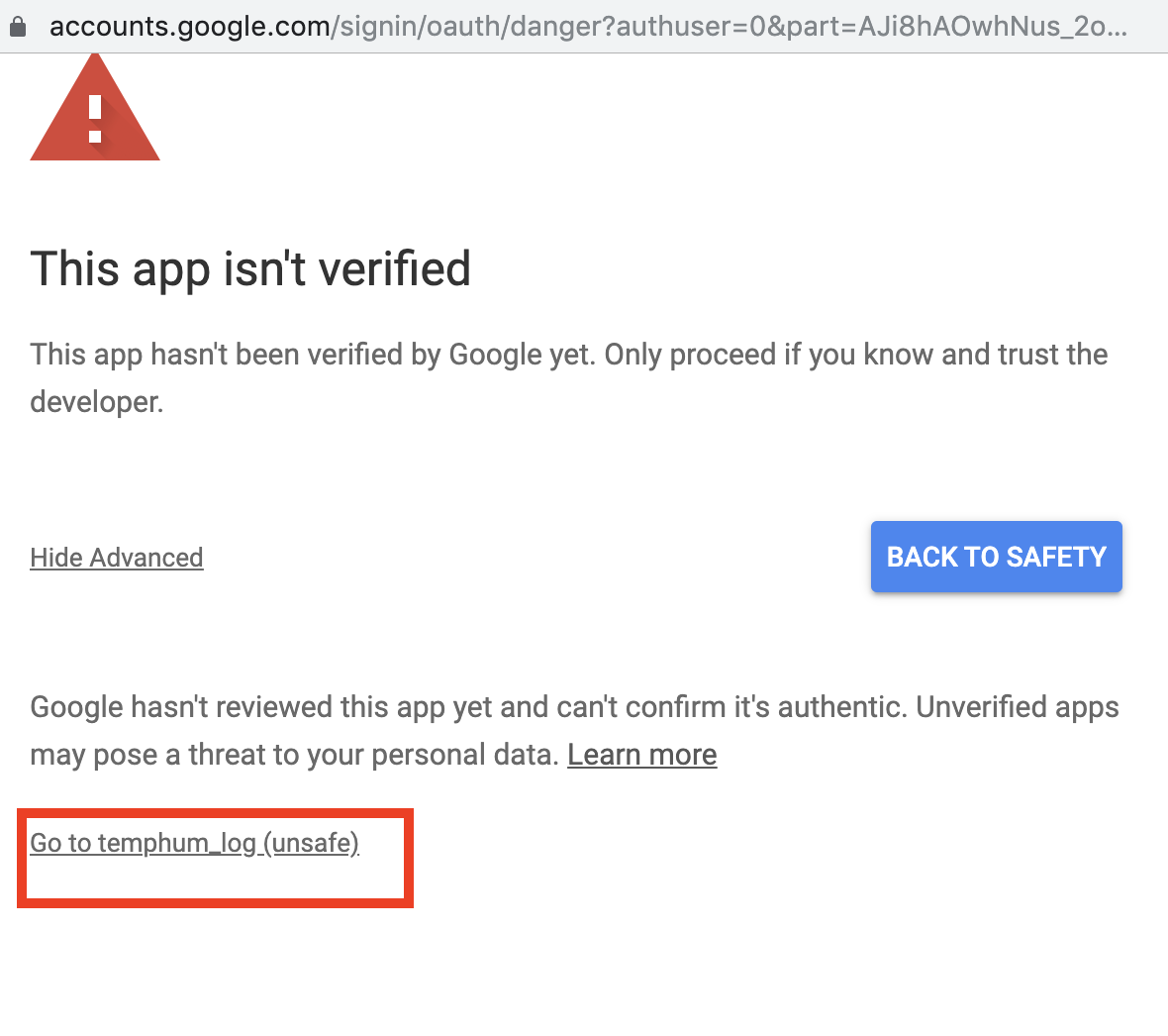
12. Proceed by clicking the goto “your script name”(unsafe) button highlighted below.
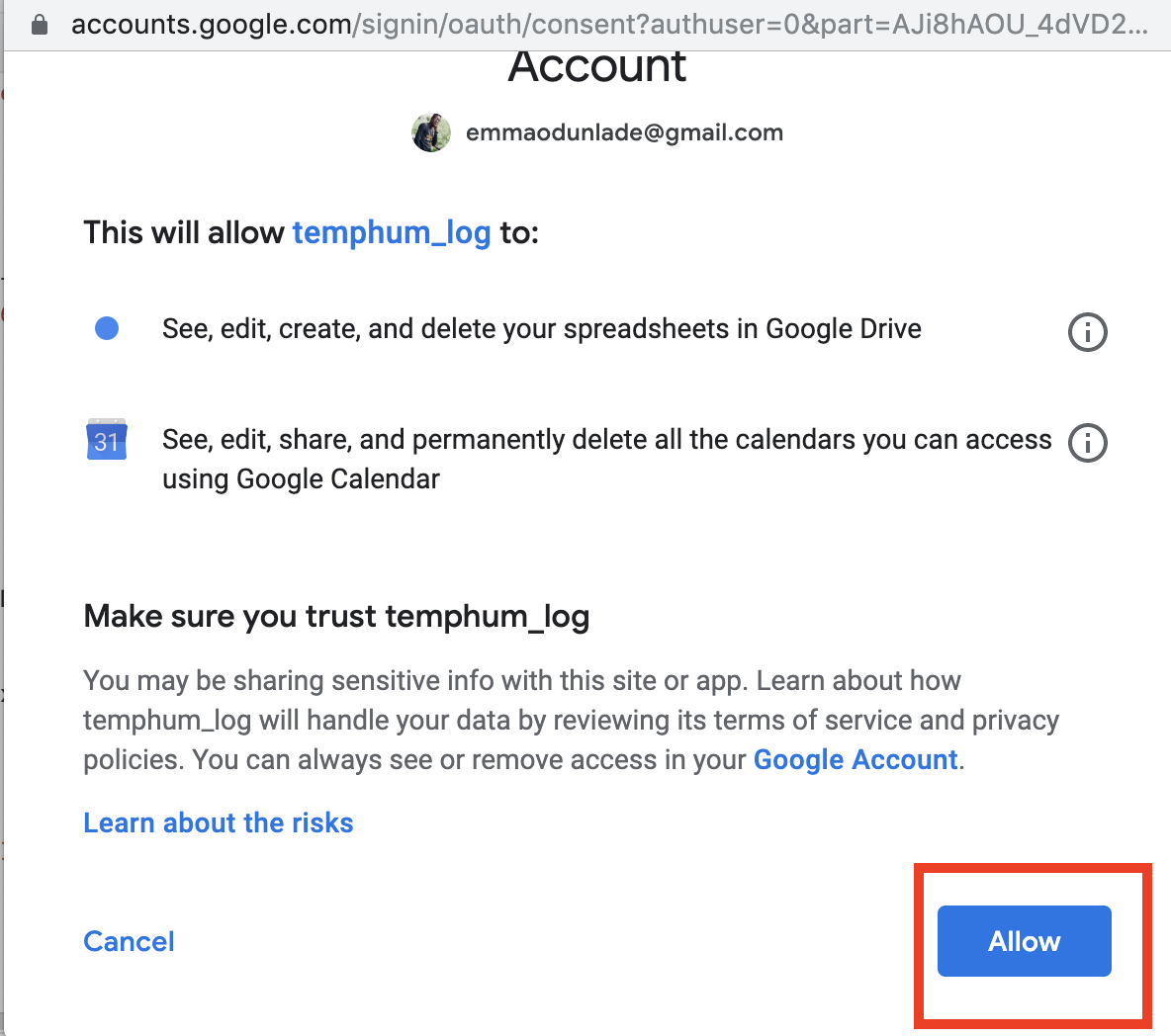
13. Ascribe permissions to the script and allow its connection to your google account and the google sheet we created, by clicking on the allow button.
Click on allow button to connect script.
14. With this done you should now see the success page. It will provide you with the web app URL. Copy this URL and keep safe as the script ID embedded in the web app URL will be used by the Arduino code to access the google sheet.
With this done, we are now ready to write the code for our ESP8266.
Code
The algorithm behind the sketch for today’s project is quite straightforward, but the implementation, to someone not familiar with https and JSON, might require some level of practice. The main task of the code is to obtain temperature and humidity data from the DHT11 and forward the data to the google sheet via WiFi connection to the internet.
We will develop the code for today’s project using the Arduino IDE as such, if this is the first time you are developing a sketch for the Nodemcu with the Arduino IDE, you will need to install the ESP8266 board support files for the Arduino IDE. For some help on getting that done, check out this tutorial we did on the topic a while back.
To simplify the code and reduce the amount of work that needs to be done, we will use 4 major libraries including; the ESP8266WiFi library, the HTTPSRedirectlibrary, the DebugMacros which is part of the HTTPSRedirect library, and the DHT library. The ESP8266WiFi library is installed when the ESP8266 board support files are installed for the Arduino IDE. It provides an easy way for users to access the robust WiFi implementation on the NodeMCU.The HTTPSRedirect library is based on the Wifi library. It provides the user with feature rich easy of communicating with servers via http or https. One of the requirements for HTTPS communication is connection certificates or in this case SHA-1 fingerprints of the websites. The debug macros library helps store and process request in that line. Finally, ther is the DHT library. It is used to facilitate easy interaction with the DHT11 to pull the temperature and humidity data with few lines of code.
As usual, I will do a “run through” of the code explaining the parts I feel might be new or difficult to grab.
We start the sketch, as usual, by including the libraries that will be used, followed by the declaration of the pin of the NodeMCU to which the DHT11 is connected and the creation of an instance of the DHT library.
#include <ESP8266WiFi.h>
#include "HTTPSRedirect.h"
#include "DebugMacros.h"
#include <DHT.h>

#define DHTPIN D4                   // Pin to which DHT is connected
#define DHTTYPE DHT11               // Declare DHT Type
DHT dht(DHTPIN, DHTTYPE);
Next, define variables that will be used to store temperature and humidity data after which we provide the credentials of the WiFi (router) through which our device is meant to access the internet.
float h;
float t;
String sheetHumid = "";
String sheetTemp = "";

const char* ssid = " ";                //Put wifi ssid within the quotes
const char* password = " ";         //Put WiFi password within the quotes
Next, we create variables to hold several google server credentials including the host address, the Gscript ID we obtained earlier and the port number which is usually 443 for https.
const char* host = "script.google.com";
const char *GScriptId = "enter your GSCript ID here"; // Replace with your own google script id
const int httpsPort = 443; //the https port is same
Next we define the URL to the Google Sheet where the data will be written, using the GscriptID as the reference. After that we create a payload with formatted in JSON to specify how the data should be sent to the google sheet.
// echo | openssl s_client -connect script.google.com:443 |& openssl x509 -fingerprint -noout
const char* fingerprint = "";

//const uint8_t fingerprint[20] = {};

String url = String("/macros/s/") + GScriptId + "/exec?value=Temperature";  // Write Teperature to Google Spreadsheet at cell A1
// Fetch Google Calendar events for 1 week ahead
String url2 = String("/macros/s/") + GScriptId + "/exec?cal";  // Write to Cell A continuosly

//replace with sheet name not with spreadsheet file name taken from google
String payload_base =  "{\"command\": \"appendRow\", \
                    \"sheet_name\": \"temphum\", \
                       \"values\": ";
String payload = "";
With that done, we then create an Https client which will be managing all the connections and move to the void setup() function.
HTTPSRedirect* client = nullptr;
We start the void setup by initializing serial communication to enable us use the serial monitor for debugging.
void setup() {
  delay(1000);
  Serial.begin(115200);
Next, we initialize the DHT and initiate WiFi connection to the access point provided.
Next, we create a client using the httpsredirect library for connection purposes. One notable thing done within this block of code is that we set the security status of the connection as insecure. This is to enable us connect without necessarily verifying the certificate of the server. The connection is retried severally and its status is displayed on the serial monitor for debug purposes.
// Use HTTPSRedirect class to create a new TLS connection
client = new HTTPSRedirect(httpsPort);
client->setInsecure();
client->setPrintResponseBody(true);
client->setContentTypeHeader("application/json");
Serial.print("Connecting to ");
Serial.println(host); //try to connect with "script.google.com"
// Try to connect for a maximum of 5 times then exit
bool flag = false;
for (int i = 0; i < 5; i++) {
int retval = client->connect(host, httpsPort);
if (retval == 1) {
flag = true;
break;
}
else
Serial.println("Connection failed. Retrying...");
}
if (!flag) {
Serial.print("Could not connect to server: ");
Serial.println(host);
Serial.println("Exiting...");
return;
}
If the connection is successful, the client fetches the spreadsheet details as well as the google calendar details to know which row was data last updated to. The buffer is then cleared by deleting the client to reduce the amount of memory being used.
Serial.println("\nWrite into cell 'A1'");
Serial.println("------>");
// fetch spreadsheet data
client->GET(url, host);
Serial.println("\nGET: Fetch Google Calendar Data:");
Serial.println("------>");
// fetch spreadsheet data
client->GET(url2, host);
Serial.println("\nStart Sending Sensor Data to Google Spreadsheet");
// delete HTTPSRedirect object
delete client;
client = nullptr;
}
Next, we move to the void loop() function.
We start the function by obtaining temperature and humidity information from the DHT, checking to see if there is any error in the Data and displaying the data obtained on the serial monitor.
h = dht.readHumidity(); // Reading temperature or humidity takes about 250 milliseconds!
t = dht.readTemperature(); // Read temperature as Celsius (the default)
if (isnan(h) || isnan(t)) { // Check if any reads failed and exit early (to try again).
Serial.println(F("Failed to read from DHT sensor!"));
return;
}
Serial.print("Humidity: "); Serial.print(h);
sheetHumid = String(h) + String("%"); //convert integer humidity to string humidity
Serial.print("% Temperature: "); Serial.print(t); Serial.println("°C ");
sheetTemp = String(t) + String("°C");
Next, we create connection session variables and add the data obtained from the DHT to the header payload.
static int error_count = 0;
static int connect_count = 0;
const unsigned int MAX_CONNECT = 20;
static bool flag = false;
payload = payload_base + "\"" + sheetTemp + "," + sheetHumid + "\"}";
The client is created, connected to the host and the new payload is uploaded to the google sheet. If any error is detected, the system retries for 3 times after which it clears its buffer and automatically restarts the Nodemcu by triggering the watchdog timer.
if (!flag) {
client = new HTTPSRedirect(httpsPort);
client->setInsecure();
flag = true;
client->setPrintResponseBody(true);
client->setContentTypeHeader("application/json");
}
if (client != nullptr) {
if (!client->connected()) {
client->connect(host, httpsPort);
client->POST(url2, host, payload, false);
Serial.print("Sent : "); Serial.println("Temp and Humid");
}
}
else {
DPRINTLN("Error creating client object!");
error_count = 5;
}
if (connect_count > MAX_CONNECT) {
connect_count = 0;
flag = false;
delete client;
return;
}
Serial.println("POST or SEND Sensor data to Google Spreadsheet:");
if (client->POST(url2, host, payload)) {
;
}
else {
++error_count;
DPRINT("Error-count while connecting: ");
DPRINTLN(error_count);
}
if (error_count > 3) {
Serial.println("Halting processor...");
delete client;
client = nullptr;
Serial.printf("Final free heap: %u\n", ESP.getFreeHeap());
Serial.printf("Final stack: %u\n", ESP.getFreeContStack());
Serial.flush();
ESP.deepSleep(0);
}
A delay of 2 seconds is provided at the end of the code to give a breather to the DHT as specified in its datasheet.
delay(2000); // keep delay of minimum 2 seconds as dht allow reading after 2 seconds interval and also for google sheet
}
The code runs in a loop so whenever a new data is provided by the DHT, it Is uploaded to the google sheet.
The complete code for the project is provided below and attached under the download section.
#include <ESP8266WiFi.h>
#include "HTTPSRedirect.h"
#include "DebugMacros.h"
#include <DHT.h>
#define DHTPIN D4 // what digital pin we're connected to
#define DHTTYPE DHT11 // select dht type as DHT 11 or DHT22
DHT dht(DHTPIN, DHTTYPE);
float h;
float t;
String sheetHumid = "";
String sheetTemp = "";
const char* ssid = " "; //Put wifi ssid within the quotes
const char* password = " "; //Put WiFi password within the quotes
const char* host = "script.google.com";
const char *GScriptId = "enter your GSCript ID here"; // Replace with your own google script id
const int httpsPort = 443; //the https port is same
// echo | openssl s_client -connect script.google.com:443 |& openssl x509 -fingerprint -noout
const char* fingerprint = "";
//const uint8_t fingerprint[20] = {};
String url = String("/macros/s/") + GScriptId + "/exec?value=Temperature"; // Write Teperature to Google Spreadsheet at cell A1
// Fetch Google Calendar events for 1 week ahead
String url2 = String("/macros/s/") + GScriptId + "/exec?cal"; // Write to Cell A continuosly
//replace with sheet name not with spreadsheet file name taken from google
String payload_base = "{\"command\": \"appendRow\", \
\"sheet_name\": \"temphum\", \
\"values\": ";
String payload = "";
HTTPSRedirect* client = nullptr;
// used to store the values of free stack and heap before the HTTPSRedirect object is instantiated
// so that they can be written to Google sheets upon instantiation
void setup() {
delay(1000);
Serial.begin(115200);
dht.begin();     //initialise DHT11

Serial.println();
Serial.print("Connecting to wifi: ");
Serial.println(ssid);

WiFi.begin(ssid, password);
while (WiFi.status() != WL_CONNECTED) {
  delay(500);
  Serial.print(".");
}
Serial.println("");
Serial.println("WiFi connected");
Serial.println("IP address: ");
Serial.println(WiFi.localIP());
// Use HTTPSRedirect class to create a new TLS connection
client = new HTTPSRedirect(httpsPort);
client->setInsecure();
client->setPrintResponseBody(true);
client->setContentTypeHeader("application/json");
Serial.print("Connecting to ");
Serial.println(host);          //try to connect with "script.google.com"

// Try to connect for a maximum of 5 times then exit
bool flag = false;
for (int i = 0; i < 5; i++) {
  int retval = client->connect(host, httpsPort);
  if (retval == 1) {
    flag = true;
    break;
  }
  else
    Serial.println("Connection failed. Retrying...");
}

if (!flag) {
  Serial.print("Could not connect to server: ");
  Serial.println(host);
  Serial.println("Exiting...");
  return;
}
// Finish setup() function in 1s since it will fire watchdog timer and will reset the chip.
//So avoid too many requests in setup()
  Serial.println("\nWrite into cell 'A1'");
  Serial.println("------>");
  // fetch spreadsheet data
  client->GET(url, host);

  Serial.println("\nGET: Fetch Google Calendar Data:");
  Serial.println("------>");
  // fetch spreadsheet data
  client->GET(url2, host);

 Serial.println("\nStart Sending Sensor Data to Google Spreadsheet");


  // delete HTTPSRedirect object
  delete client;
  client = nullptr;
}
void loop() {
h = dht.readHumidity();                                              // Reading temperature or humidity takes about 250 milliseconds!
 t = dht.readTemperature();                                           // Read temperature as Celsius (the default)
 if (isnan(h) || isnan(t)) {                                                // Check if any reads failed and exit early (to try again).
   Serial.println(F("Failed to read from DHT sensor!"));
   return;
 }
 Serial.print("Humidity: ");  Serial.print(h);
 sheetHumid = String(h) + String("%");                                         //convert integer humidity to string humidity
 Serial.print("%  Temperature: ");  Serial.print(t);  Serial.println("°C ");
 sheetTemp = String(t) + String("°C");
static int error_count = 0;
  static int connect_count = 0;
  const unsigned int MAX_CONNECT = 20;
  static bool flag = false;

  payload = payload_base + "\"" + sheetTemp + "," + sheetHumid + "\"}";
if (!flag) {
  client = new HTTPSRedirect(httpsPort);
  client->setInsecure();
  flag = true;
  client->setPrintResponseBody(true);
  client->setContentTypeHeader("application/json");
}

if (client != nullptr) {
  if (!client->connected()) {
    client->connect(host, httpsPort);
    client->POST(url2, host, payload, false);
    Serial.print("Sent : ");  Serial.println("Temp and Humid");
  }
}
else {
  DPRINTLN("Error creating client object!");
  error_count = 5;
}

if (connect_count > MAX_CONNECT) {
  connect_count = 0;
  flag = false;
  delete client;
  return;
}

Serial.println("POST or SEND Sensor data to Google Spreadsheet:");
if (client->POST(url2, host, payload)) {
  ;
}
else {
  ++error_count;
  DPRINT("Error-count while connecting: ");
  DPRINTLN(error_count);
}

if (error_count > 3) {
  Serial.println("Halting processor...");
  delete client;
  client = nullptr;
  Serial.printf("Final free heap: %u\n", ESP.getFreeHeap());
  Serial.printf("Final stack: %u\n", ESP.getFreeContStack());
  Serial.flush();
  ESP.deepSleep(0);
}
  delay(2000);    // keep delay of minimum 2 seconds as dht allow reading after 2 seconds interval and also for google sheet
}
Demo
Connect the setup to your computer, launch the Arduino IDE, paste the code, verify and upload to your board. With the upload done, open the serial monitor to ensure the WiFi is connected and there are no issues. Head to the Google sheet, you should now see temperature and humidity data as they stream to the cloud from your device.
Demo
To take things further, you can hook up a python script to parse the data being logged on the google sheet and generate all sort of graphs and insights. One other thing you could do is to add location data to the spreadsheet, and display it all on Google map.
That’s it for today’s tutorial guys. Thanks for reading and as usual, feel free to reach out to me via the comment section if you get stuck anywhere.
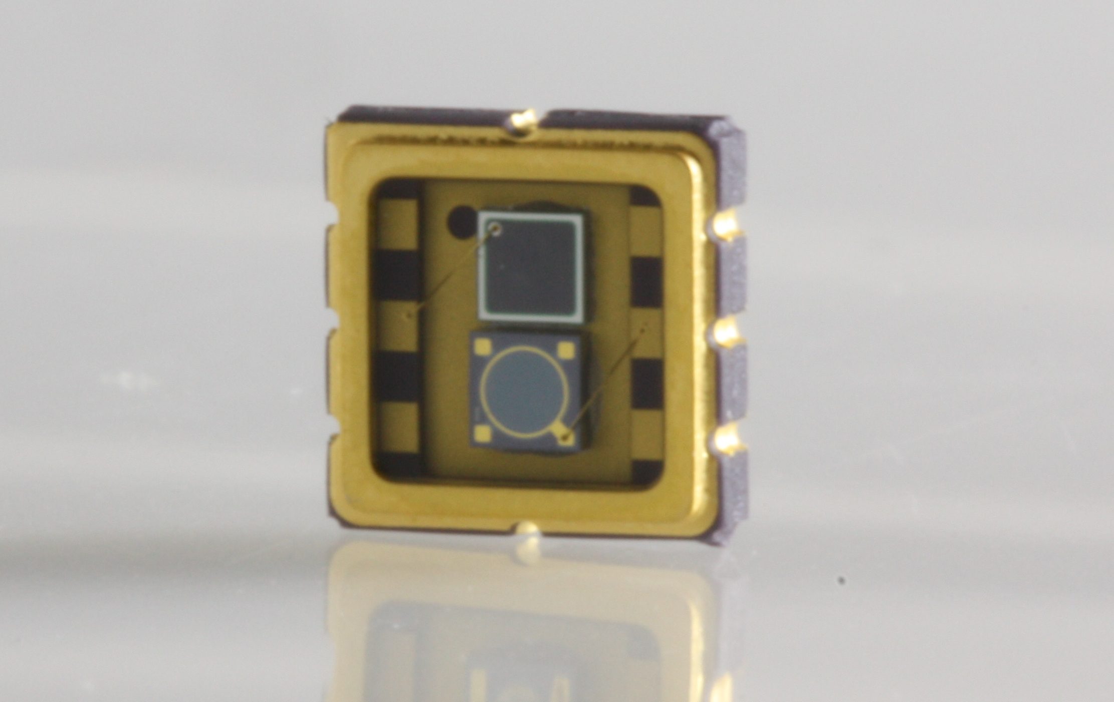
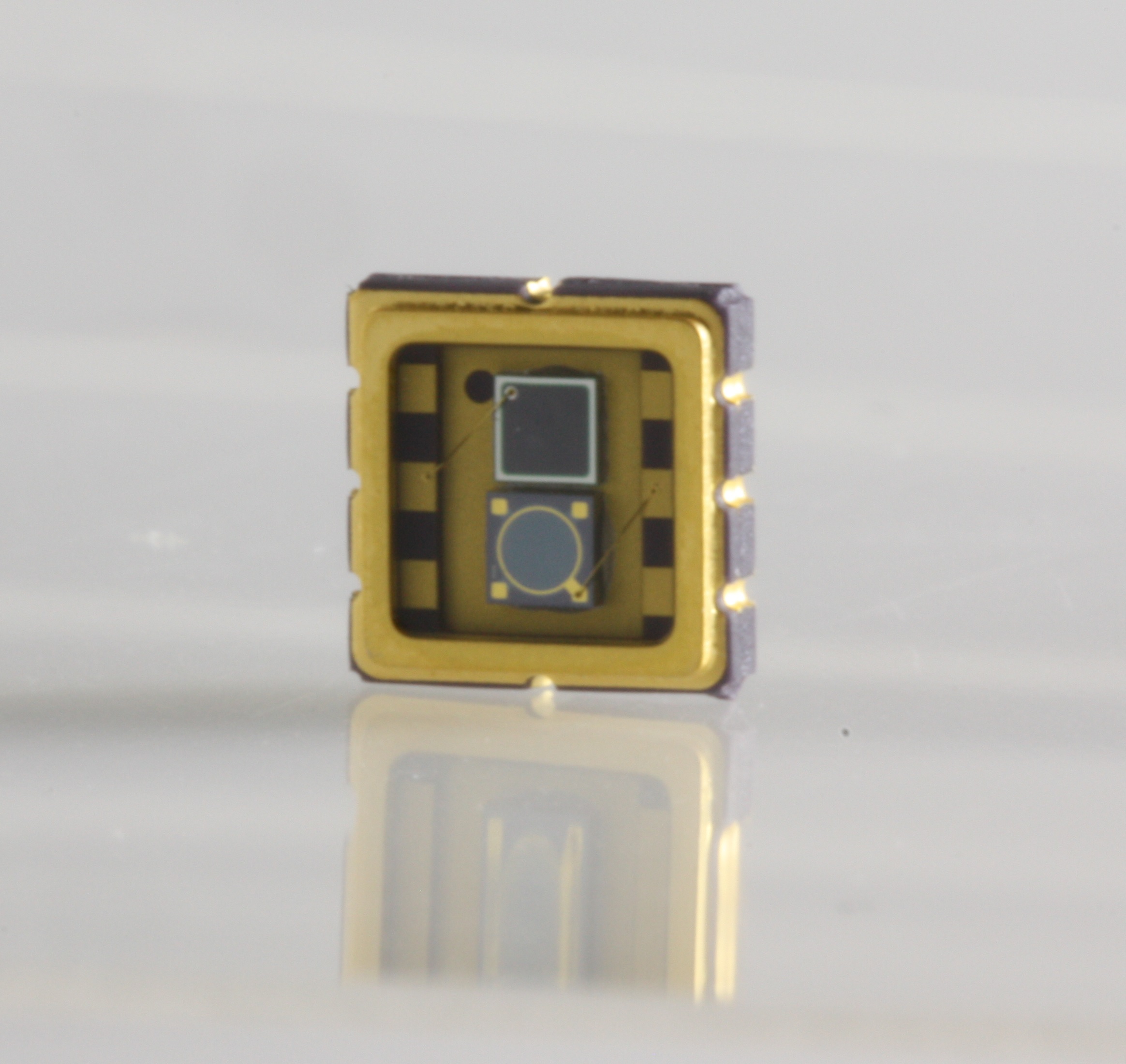
Marktech Optoelectronics, Inc. (Marktech), a privately-held, VOSB-certified, leading designer and manufacturer of standard and custom optoelectronics components and assemblies, including ultraviolet (UV), visible (VIS), near-infrared (NIR), and short-wave infrared (SWIR) emitters, detectors, InP epiwafers and other materials, today announced the global market introduction of its Models MT03-041 (TO-5) and MT03-047 (SMD), two new broadband hybrid Silicon-InGaAs photodetectors.
The industry-exclusive design of the Models MT03-041 and MT03-047 ensures versatile, accurate, reliable broadband detection over spectral ranges from UV-to-VIS-to-SWIR, with 250 nm (UV) to 1750 nm (SWIR) enhanced sensitivity. This wide dynamic range includes 365 nm blue-green enhanced Silicon-based and 1300 nm InGaAs-based detection, respectively; ultra-low-noise measurement performance; and high shunt resistance. The detectors are seamlessly integrated within a single, compact thru-hole or SMD package. They are also both REACH and RoHS compliant.
Small-to-medium-sized quantities of standard Models MT03-041 (TO-5) and MT03-047 (SMD) are typically available with 24-hour shipment from stock via Marktech global distribution partner, Digi-Key Electronics. Optional accessories for Models MT03-041 (TO-5) and MT03-047 (SMD), also available from Marktech, include UV-to-IR-to-SWIR range emitters. Each emitter may be mechanically and spectrally matched, then combined with the photodetector as a single, compact package. Custom designs may be produced in as few as 6-8 weeks from customer prototype approvals. Please consult Marktech’s Latham, New York global corporate headquarters and R&D center for assistance.
Typical applications for Marktech broadband hybrid Silicon-InGaAs photodetectors include medical, industrial, high-speed communications, security and spectroscopy. For more information about Models MT03-041 (TO-5) and MT03-047 (SMD), or other products and services available from Marktech, visit www.marktechopto.com.
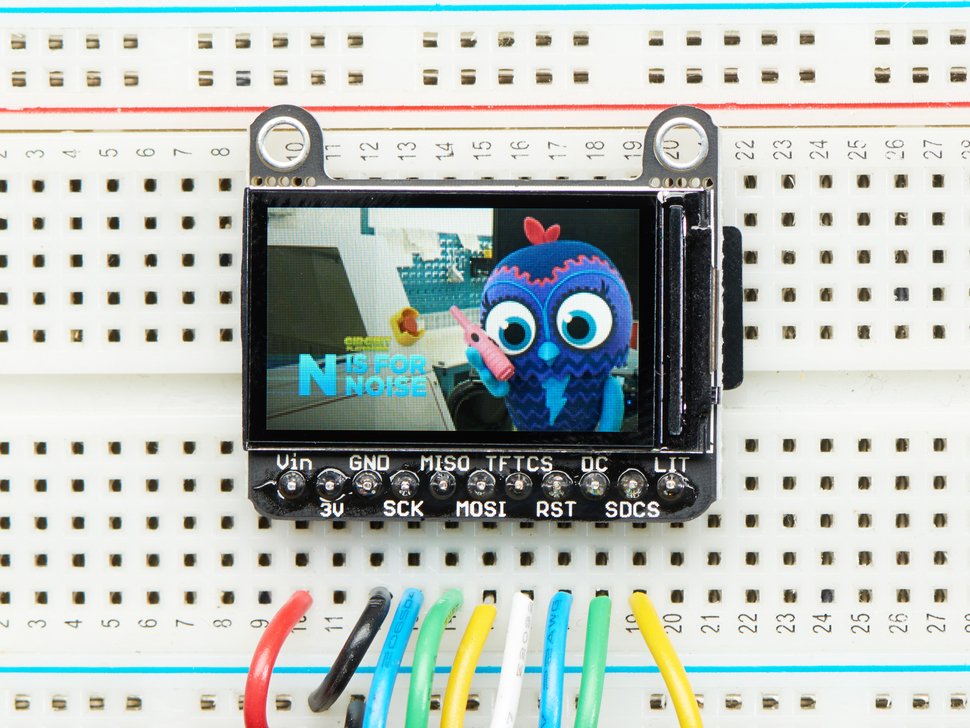
Say hello to the 1.14″ 240×135 Color TFT Display w/ MicroSD Card Breakout. It’s the size of your thumbnail, with glorious 240×135 high res pixel colour. This very very small display is only 1.14″ diagonal, packed with RGB pixels, for making very small high-density displays.
It’s so small only 1.14″ diagonal but has a high density of 260 PPI, 240×135 pixel display with full-angle viewing. It looks a lot like the 0.96″ 160×80 display but has 2.5x as many pixels. We’ve seen displays of this calibre used in smartwatches and small electronic devices but they’ve always been MIPI interface. Finally, here is one that is SPI and has a friendly display driver, so it works with any and all microcontrollers or microcomputers!
This lovely little display breakout is the best way to add a small, colourful and very bright display to any project. Since the display uses 4-wire SPI to communicate and has its own pixel-addressable frame buffer, it can be used with every kind of microcontroller. Even a very small one with low memory and few pins available! The 1.14″ display has 240×135 16-bit full-colour pixels and is an IPS display, so the colour looks great up to 80 degrees off-axis in any direction. The TFT driver (ST7789) is very similar to the popular ST7735, and the Arduino library supports it well.
The breakout has the TFT display soldered on (it uses a delicate flex-circuit connector) as well as an ultra-low-dropout 3.3V regulator and a 3/5V level shifter so you can use it with 3.3V or 5V power and logic. They also had a little space so they placed a microSD card holder so you can easily load full-colour bitmaps from a FAT16/FAT32 formatted microSD card.
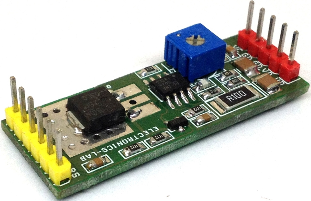
The project published here is a solid state power switch with current limiting that prevents damage to host devices from faulty load conditions. This analog current limit switch have low on-resistance P-channel MOSFET and INA202 driver IC from Texas instrument. The project operate from input voltage in the range 5V to 24V and can handle current up to 2Amps .The versatile project can be used in Smart Power applications. It is widely used to clamp the overload current, deliver constant current.
The project provides 2A current, if load current increases more than set point (2amps) automatically isolates the switch. The over-current limit threshold is set to 2 Amps but it can be programmed using an external resistor R7 and PR1 and by changing value of Shunt resistor R1, refer data sheet of INA202 for more information for current adjustment and current limit. Circuit also requires 5V logic supply other than the load supply. Trimmer potentiometer helps to set the threshold current. Setting the output is simple using trimmer pot, turn the trimmer potentiometer counter clockwise and connect current meter between load , tie the reset wire to VCC 5V switch on the logic supply and logic supply, turn the pot till it is latches the output. D1 is power LED.
Current Limit Solid State Power Switch with Latch – [Link]