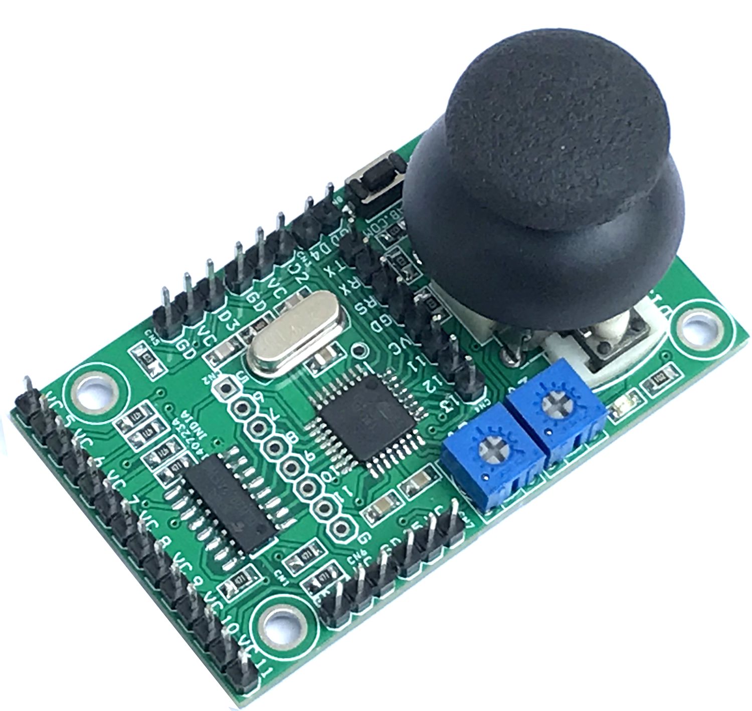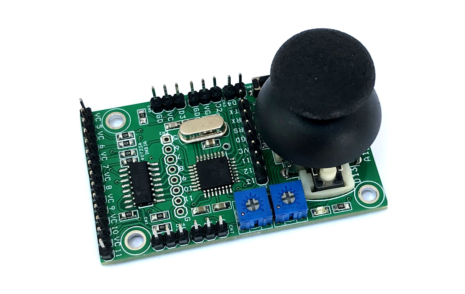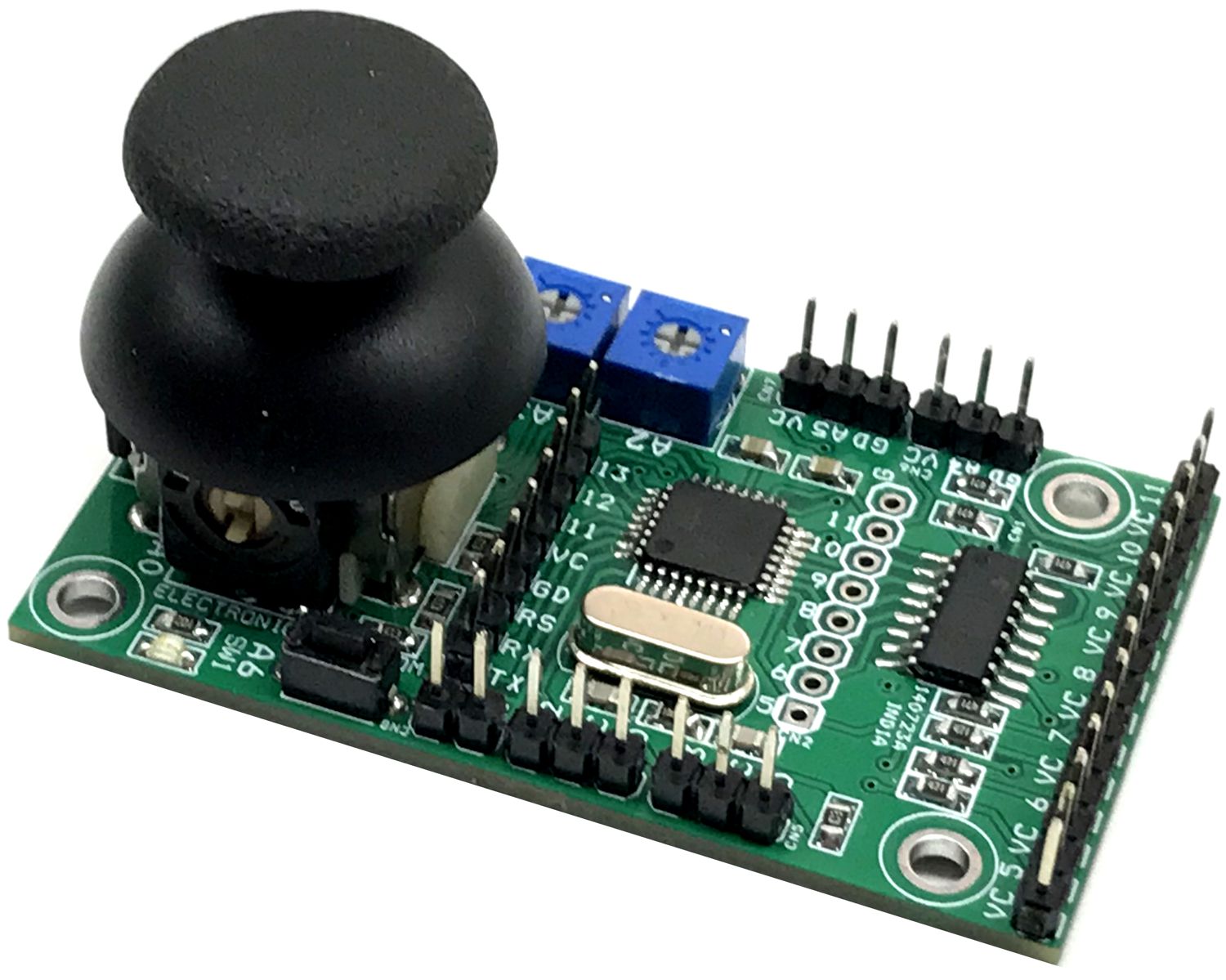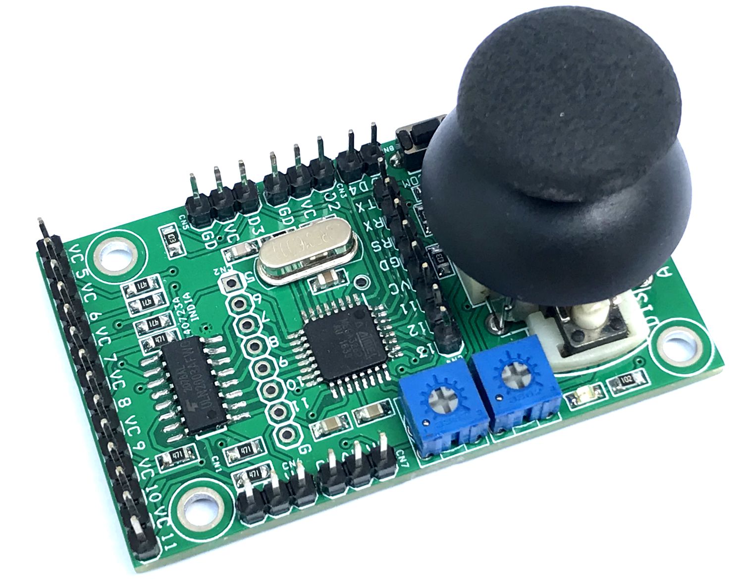
This is a pulse generator for a stepper motor driver using a joystick. It is a board that contains an Arduino-compatible microcontroller and circuitry for controlling up to 2-channel (2-axis) stepper motors. The board has multiple options to develop stepper motor-related control systems, from a 2-axis analog joystick to a trimmer potentiometer to a 7-channel open collector TTL output to interface stepper drivers with optocoupler inputs, etc.
Key Features of the Hardware
- ATMEGA328 Arduino Compatible Microcontroller
- Connector for Arduino Programming/Bootloader
- 2 x Axis (2 Channel Joystick) Cab used to drive stepper Forward, Reverse
- 2 x Trimmer Potentiometer Can be used to set acceleration/deacceleration or other functions.
- One Tactile Switch
- Connector for 7 Outputs Open Collector Type
- Optional Connector for Direct 7 Outputs
- Connector CN3 and CN5 for Limits switch or other function (with Pull-ups)
- Connector CN6 and CN7 for Analog Input
- Connector CN8 I/O
- One Tactile Switch Internal Joystick
- ULN2003 Chip Open connector to connect with stepper drivers
- Function LED Connected to D12
- Power LED
- Breakout Connectors with Pullups to Connect Limit Switches
Features
- Power Supply 5VDC
- Two Stepper Motor Controlled Using a Joystick
- All Step and Direction Signals Open Collector Type and TTL Level (7 Outputs)
- On Board Optional Connector CN2 for Direct Output from Arduino
- Various hardware options are available for the development of many applications for stepper motors
- 4 x 3 mm Mounting Holes
- PCB Dimension 61.28 x 36.20 mm
Application
- Stepper Motor Based Linear/Rotary Actuator
- Turn Tables
- Camera Sliders
- Camera Pan Tilt Head
- Robotics Arms
- Robotics
- Automation
- Animatronics
Arduino Example Code
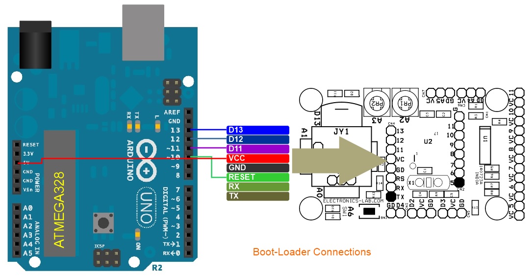
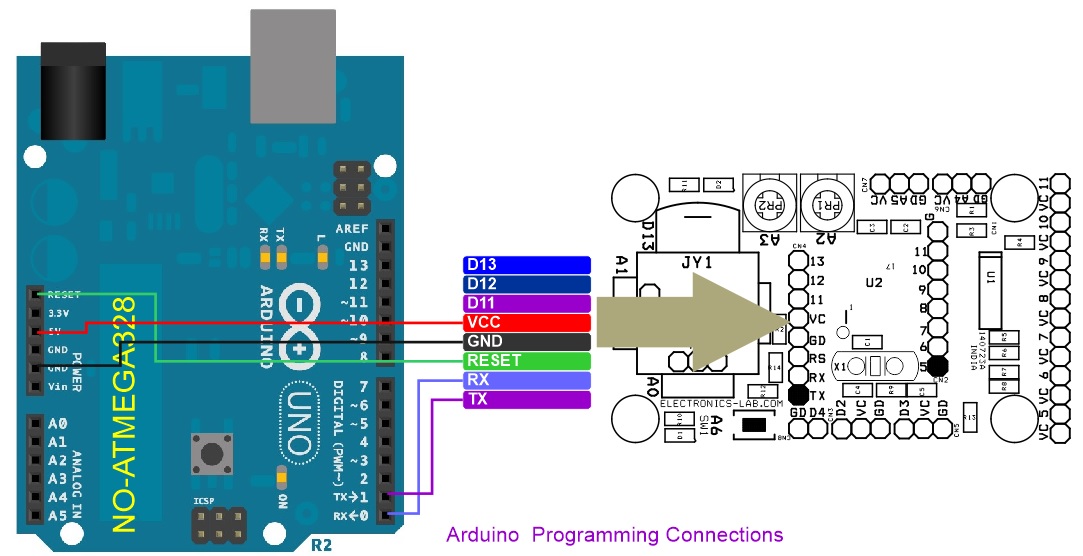
Arduino code is available for testing purposes. Before we start with a new ATMEGA328, it requires a bootloader and Arduino code. Check the link below to learn more about programming:
- https://www.electronics-lab.com/project/installing-the-arduino-bootloader-on-the-atmega328p-microcontroller/
- https://docs.arduino.cc/built-in-examples/arduino-isp/ArduinoToBreadboard
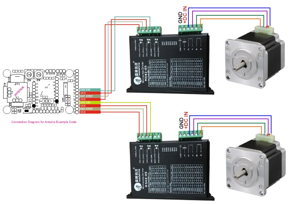
Hardware has many I/O lines. The following hardware is used in the example Arduino code:
- Joystick 2 x Axis
- Axis-1 Arduino D5 Step Pulse Out, D8 Direction Output (Outputs are Open Collector Types for Stepper drivers optocouplers)
- Axis-2 Arduino D6 Step Pulse Out, D7 Direction Output (Outputs are Open Collector Types for stepper drivers optocouplers)
The user will be able to run two stepper drivers using the joystick. Pls, check the connections diagram.
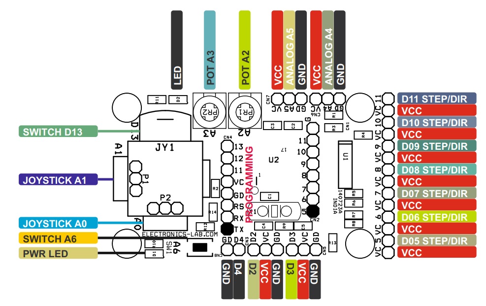
Connections and Hardware Details
- CN1: Pin 1 = OP11(D11), Pin 2 = VCC, Pin 3 = OP10(D10), Pin 4 = VCC, Pin 5 = OP9(D9), Pin 6 = VCC, Pin 7 = OP8(D8), Pin 8 = VCC, Pin 9 = OP7(D7), Pin 10 = VCC, Pin 11 = OP6(D6), Pin 12 = VCC, Pin 13 = OP5(D5), Pin 14 = VCC
- CN2: DNP (D5, D6, D6, D7, D8, D9, D10, D11) Direct I/O (Optional)
- CN3: Pin 1 = D2-Pullup, Pin 2 = VCC, Pin 3 = GND
- CN4: Pin 1 = TX, Pin 2 = RX, Pin 3 = Reset, Pin 4 = GND, Pin 5 = VC, Pin 6 = D11, Pin 7 = D12, Pin 8 = D13
- CN5: Pin 1 = D3-With Pullup, Pin 2 = VCC, Pin 3 = GND
- CN6: Pin 1 VCC, Pin 2 = A4, Pin 3 = GND
- CN7: Pin 1 VCC, Pin 2 = A5, Pin 3 = GND
- CN8: Pin 1 = D4-With Pullup, Pin 2 = GND
- SW1: Tactile Switch = Analog Pin A6
- D2: LED = D12
- D1: Power LED
- P1: Joystick X Axis = Analog A1
- P2: Joystick Y Axis = Analog A0
- PR1: Trimmer Potentiometer = Analog A2
- PR2: Trimmer Potentiometer = Analog A3
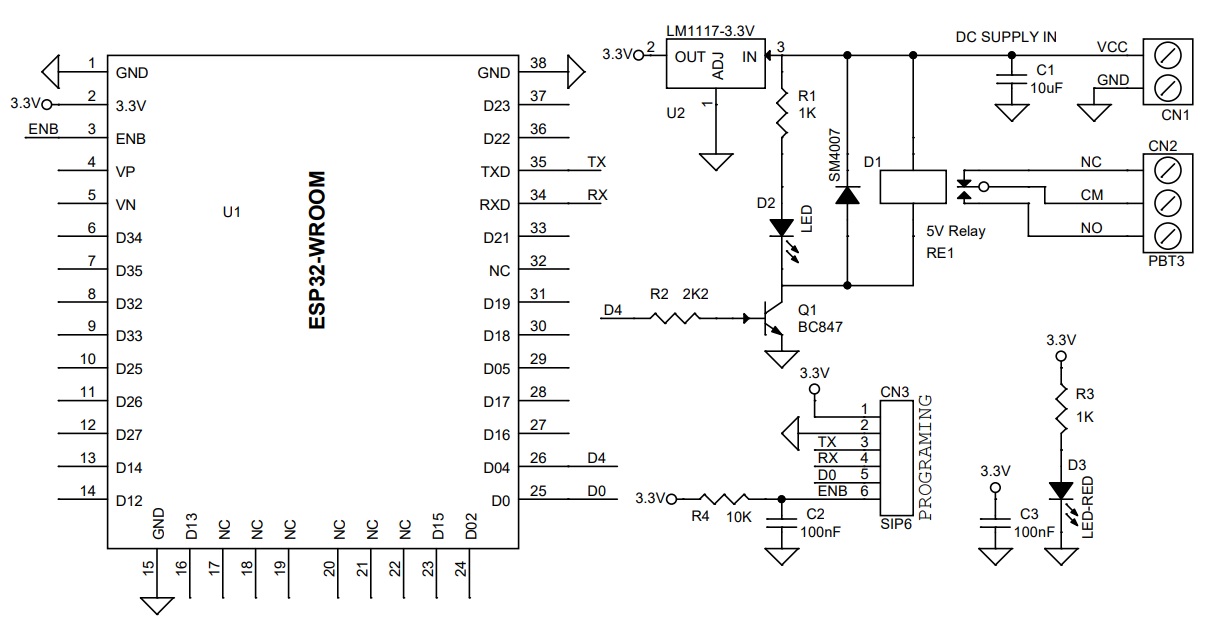
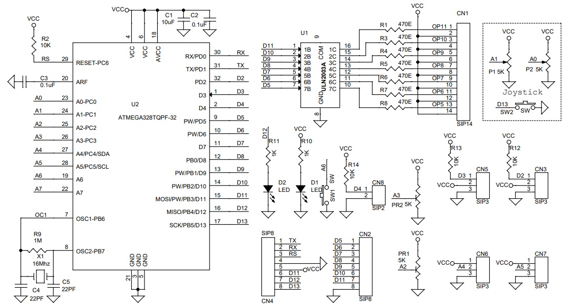
Schematic
Parts List
| NO | QNTY. | REF. | DESC | MANUFACTURER | SUPPLIER | SUPPLIER PART NO |
|---|---|---|---|---|---|---|
| 1 | 1 | CN1 | 14 PIN MALE HEADER PITCH 2.54MM | WURTH | DIGIKEY | 732-5325-ND |
| 2 | 2 | CN2,CN4 | 8 PIN MALE HEADER PITCH 2.54MM | WURTH | DIGIKEY | 732-5321-ND |
| 3 | 4 | CN3,CN5,CN6,CN7 | 3 PIN MALE HEADER PITCH 2.54MM | WURTH | DIGIKEY | 732-5316-ND |
| 4 | 1 | CN8 | 2 PIN MALE HEADER PITCH | WURTH | DIGIKEY | 732-5315-ND |
| 5 | 1 | C1 | 10uF/10V CERAMIC SMD SIZE 0805 | YAGEO/MURATA | DIGIKEY | |
| 6 | 2 | C2,C3 | 0.1uF/50V CERAMIC SMD SIZE 0805 | YAGEO/MURATA | DIGIKEY | |
| 7 | 2 | C4,C5 | 22PF/50V CERAMIC SMD SIZE 0805 | YAGEO/MURATA | DIGIKEY | |
| 8 | 2 | D1,D2 | LED RED SMD SIZE 0805 | OSRAM | DIGIKEY | 475-1278-1-ND |
| 9 | 4 | PR1,PR2 | 5K TRIMMER POTENTIOMETER | BOURNS | DIGIKEY | 3362P-502LF-ND |
| 10 | 7 | R1,R3,R4,R5,R6,R7,R8 | 470E 5% SMD SIZE 0805 | YAGEO/MURATA | DIGIKEY | |
| 11 | 4 | R2,R12,R13,R14 | 10K 5% SMD SIZE 0805 | YAGEO/MURATA | DIGIKEY | |
| 12 | 1 | R9 | 1M 5% SMD SIZE 0805 | YAGEO/MURATA | DIGIKEY | |
| 13 | 2 | R10,R11 | 1K 5% SMD SIZE 0805 | YAGEO/MURATA | DIGIKEY | |
| 14 | 1 | SW1 | TACTILE SWITCH | E-SWITCH | DIGIKEY | EG2513-ND |
| 15 | 1 | U1 | ULN2003A | TI | DIGIKEY | 296-1368-1-ND |
| 16 | 1 | U2 | ATMEGA328TQPF-32 | MICROCHIP | DIGIKEY | ATMEGA328PB-AURCT-ND |
| 17 | 1 | X1 | 16Mhz | ECS INC | DIGIKEY | X1103-ND |
| 18 | 1 | JOYSTICK P1,P2 | JOYSTICK WITH SWITCH AND POT 5/10K | C&K | DIGIKEY | 108-THB001P-ND |
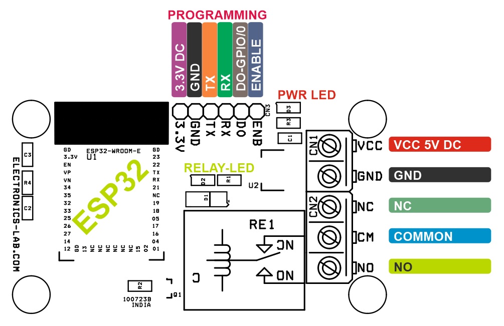
Connections
Gerber View
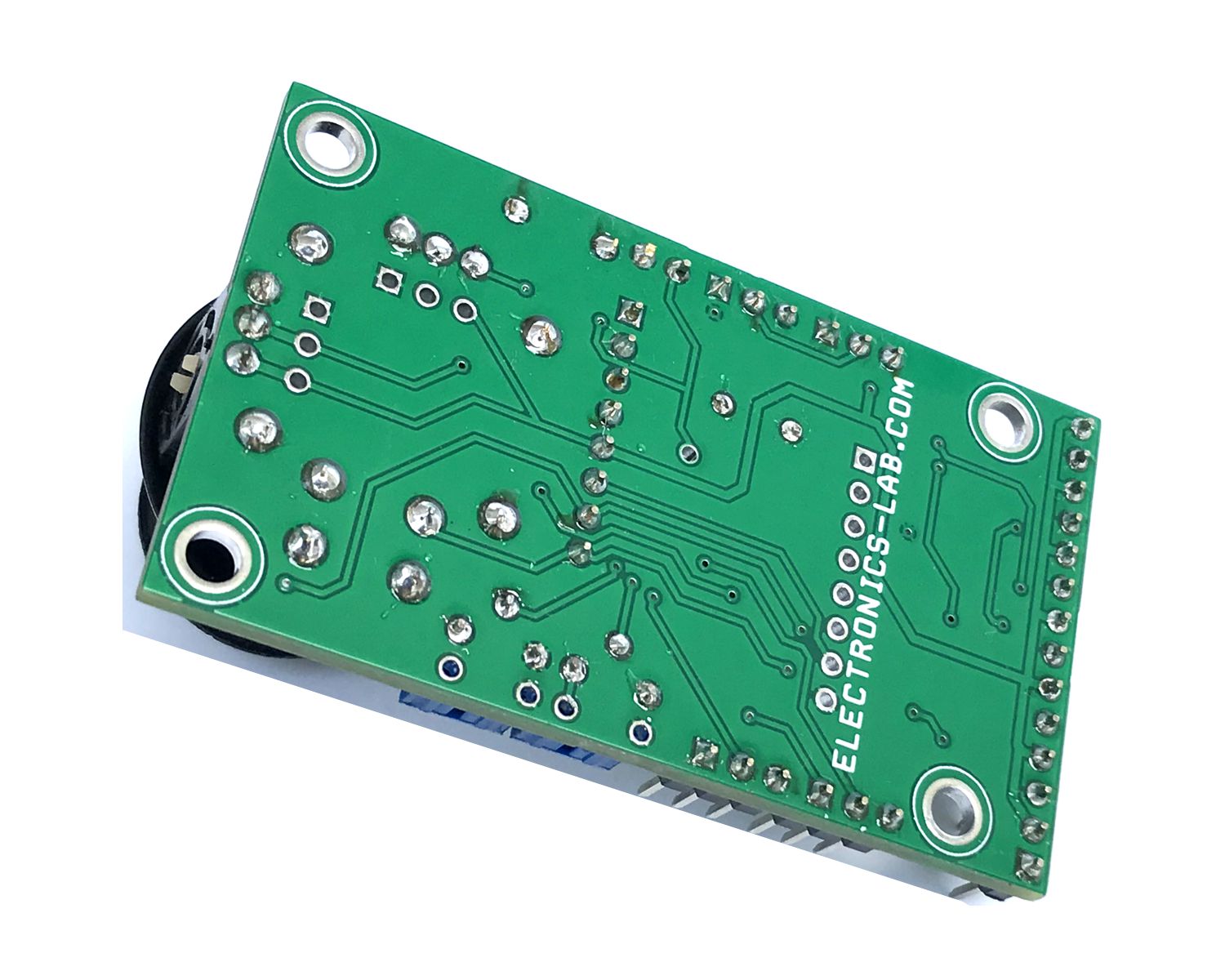
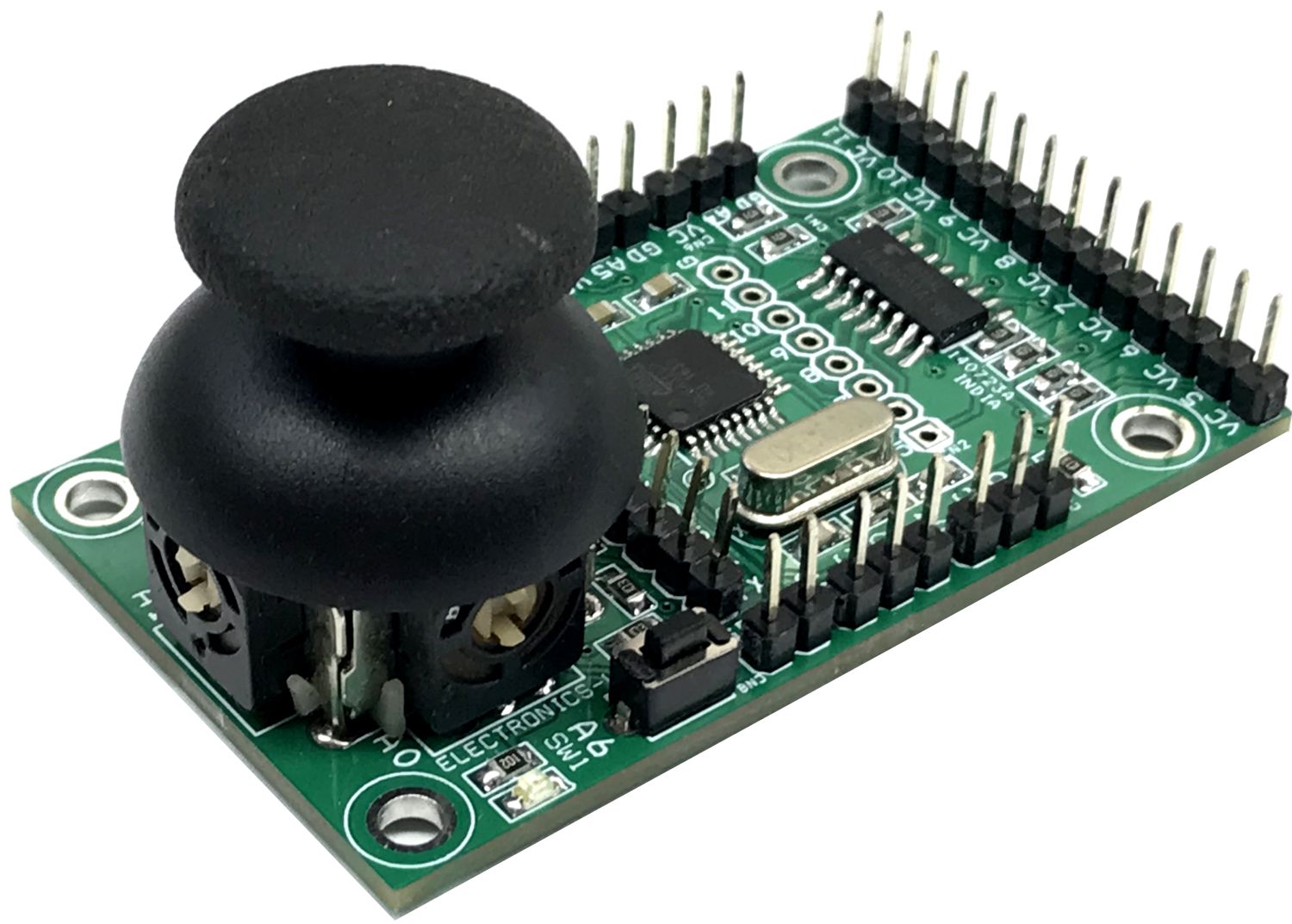
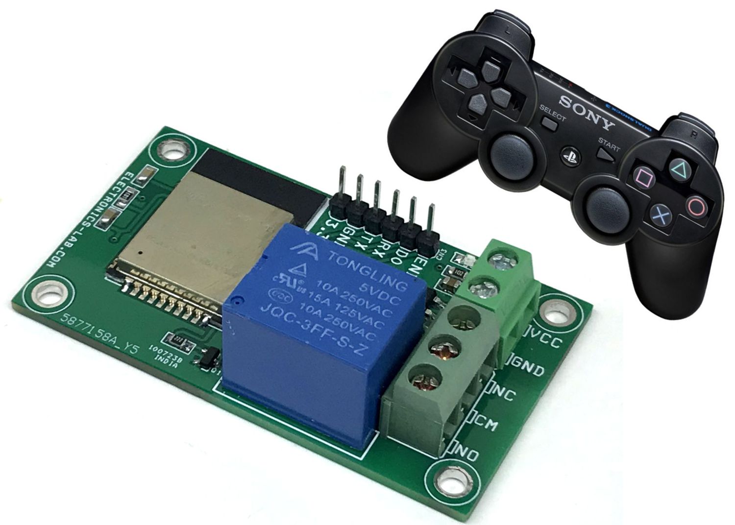
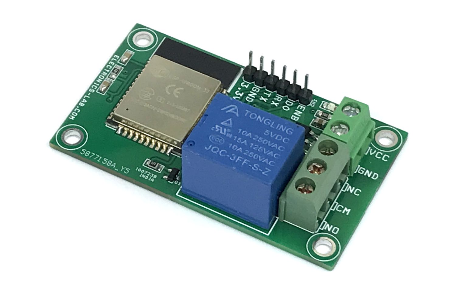
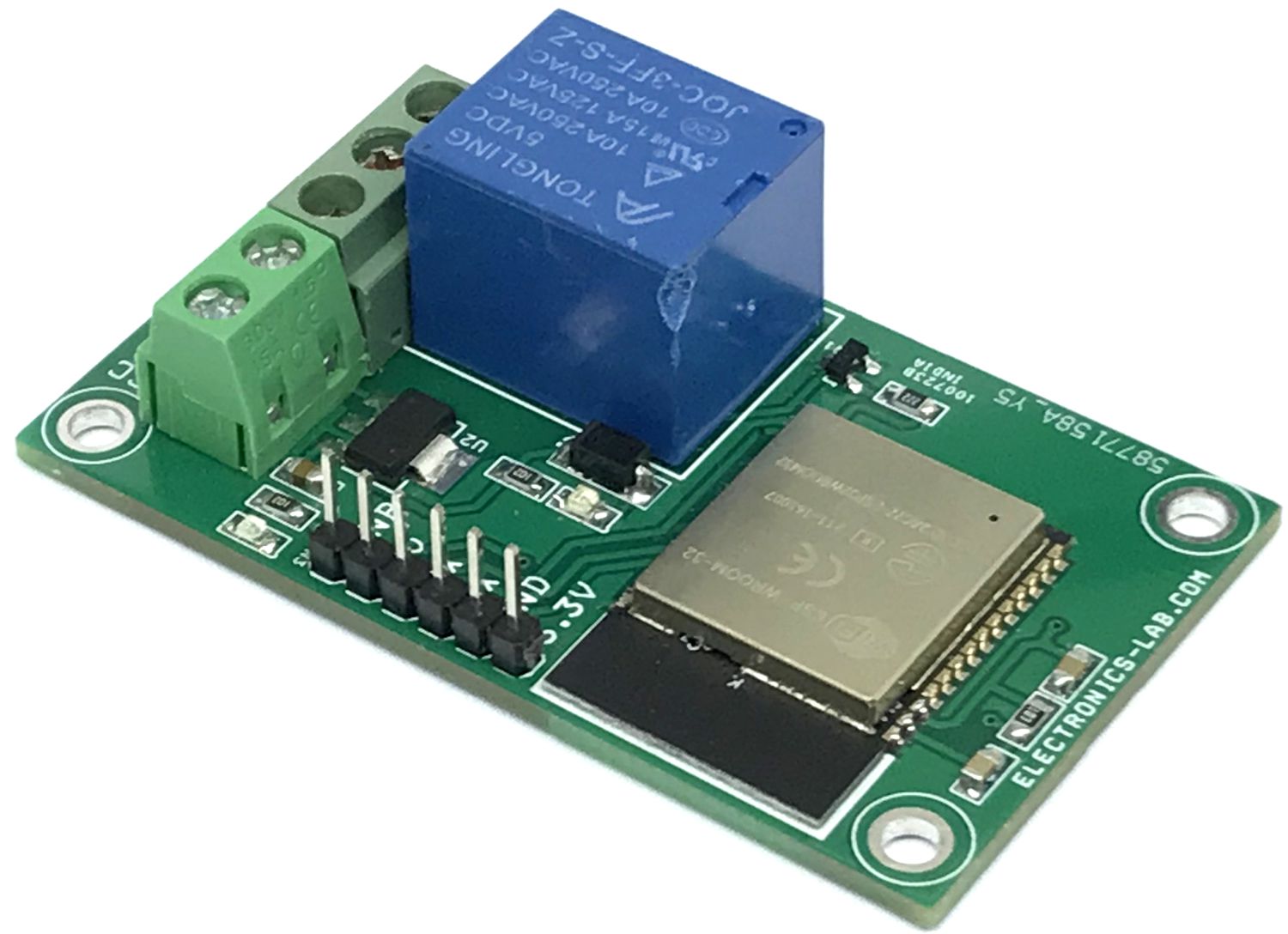
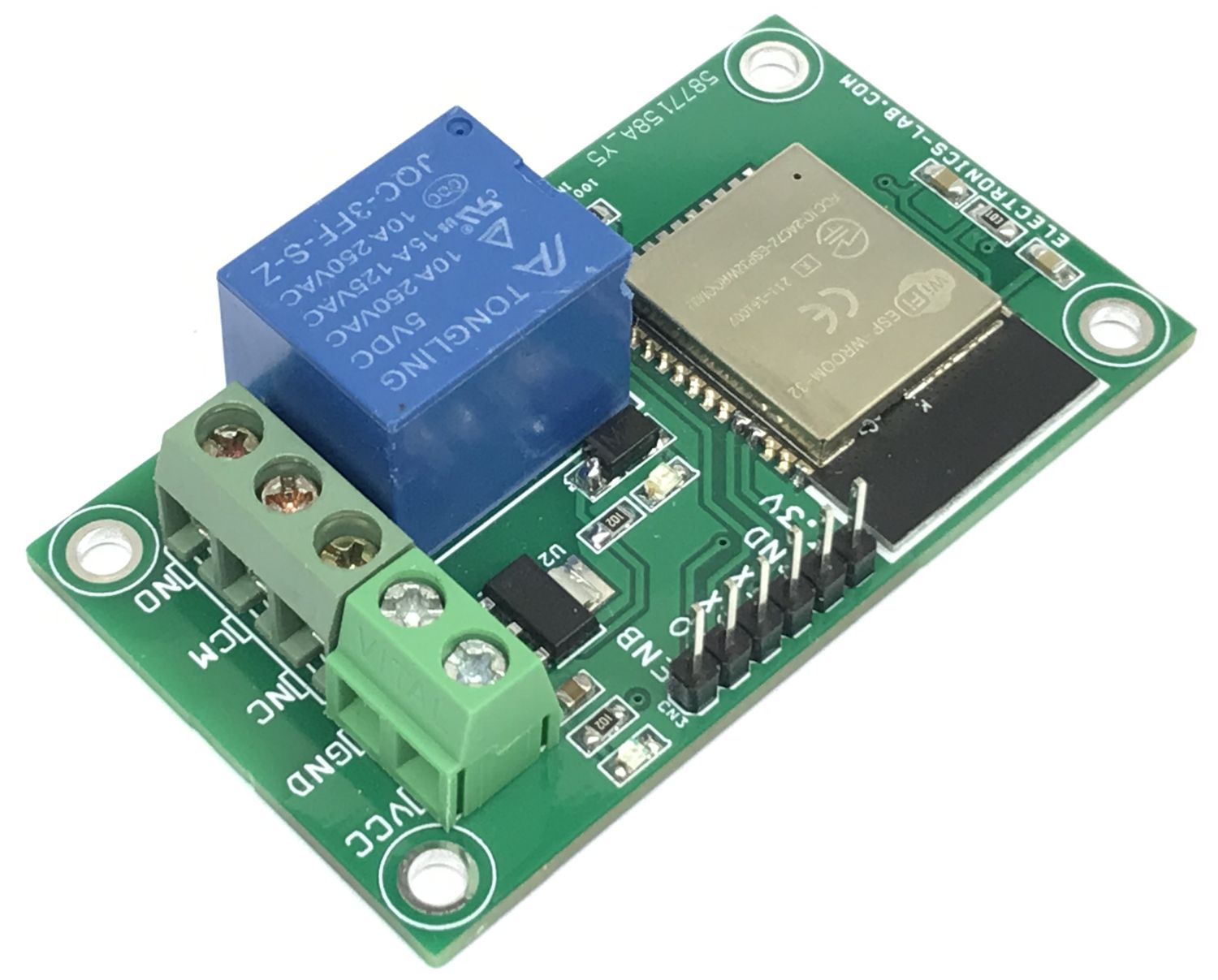
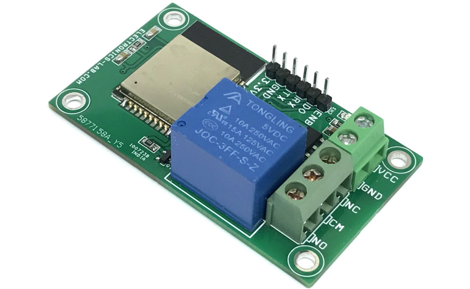
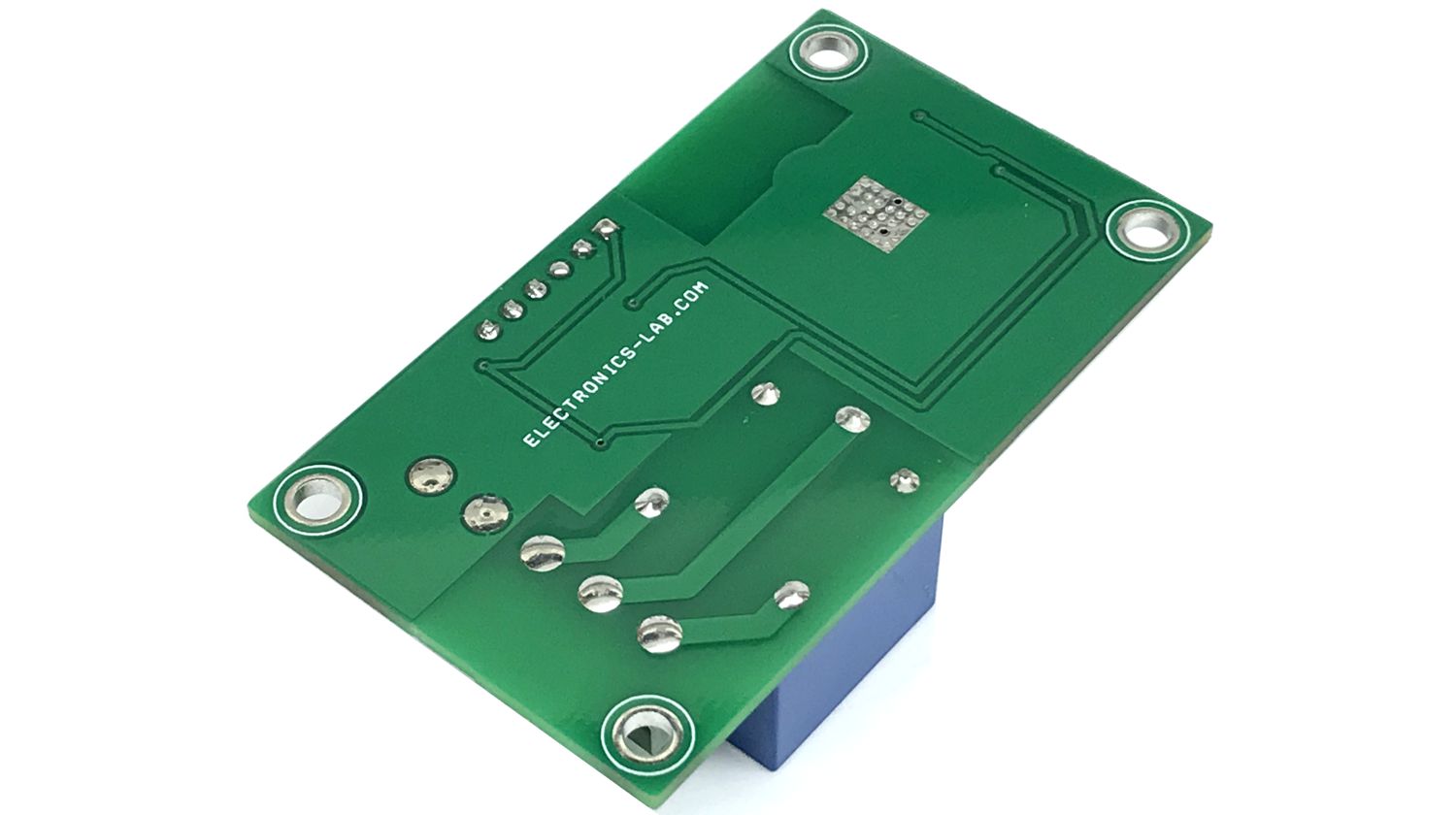
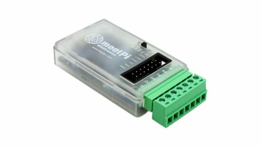
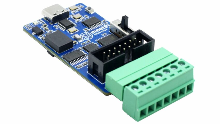
Photos