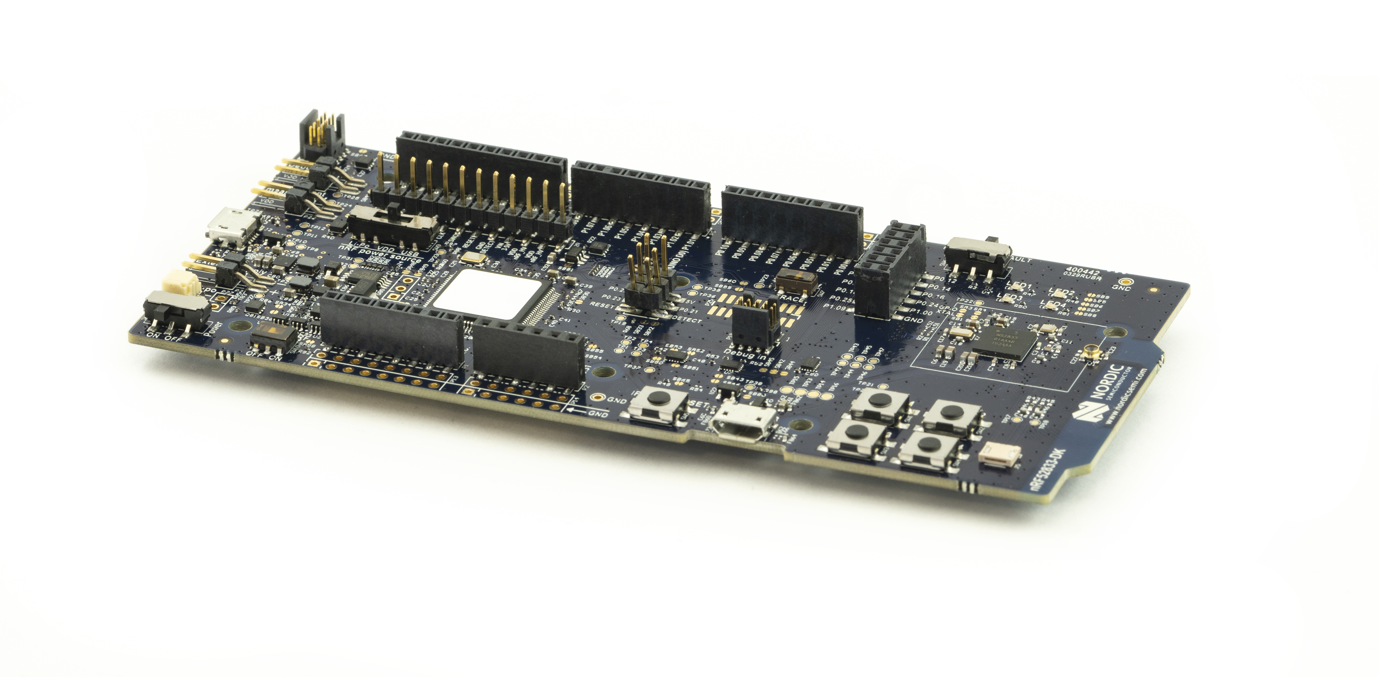
The nRF52833 DK is a versatile single board development kit for the Bluetooth® Low Energy, Bluetooth mesh, Thread, Zigbee (802.15.4), and 2.4GHz proprietary applications using the nRF52833 SoC. The kit supports all development for the nRF52833 SoC.
The kit is hardware compatible with the Arduino Uno Revision 3 standard, making it possible to use 3rd-party shields that are compatible with this standard. An included NFC antenna can be connected the kit to enable NFC-A tag functionality. The kit allows access to all I/O and interfaces via connectors and has 4 LEDs and 4 buttons which are user-programmable.
And on-board SEGGER J-link debugger allows programming and debugging both the on-board SoC and external SoCs through the debug out header. SEGGER Embedded Studio, Keil, IAR and GCC IDEs and toolchains are supported.
The DK is supported by an SDK for firmware development and a range of PC tools (Windows, MacOS and Linux) to develop end to end applications.
Key features
Affordable, rapid prototyping and development solution for nRF52833 SoC
Arduino Rev. 3 compatible connector for use with 3rd party shields
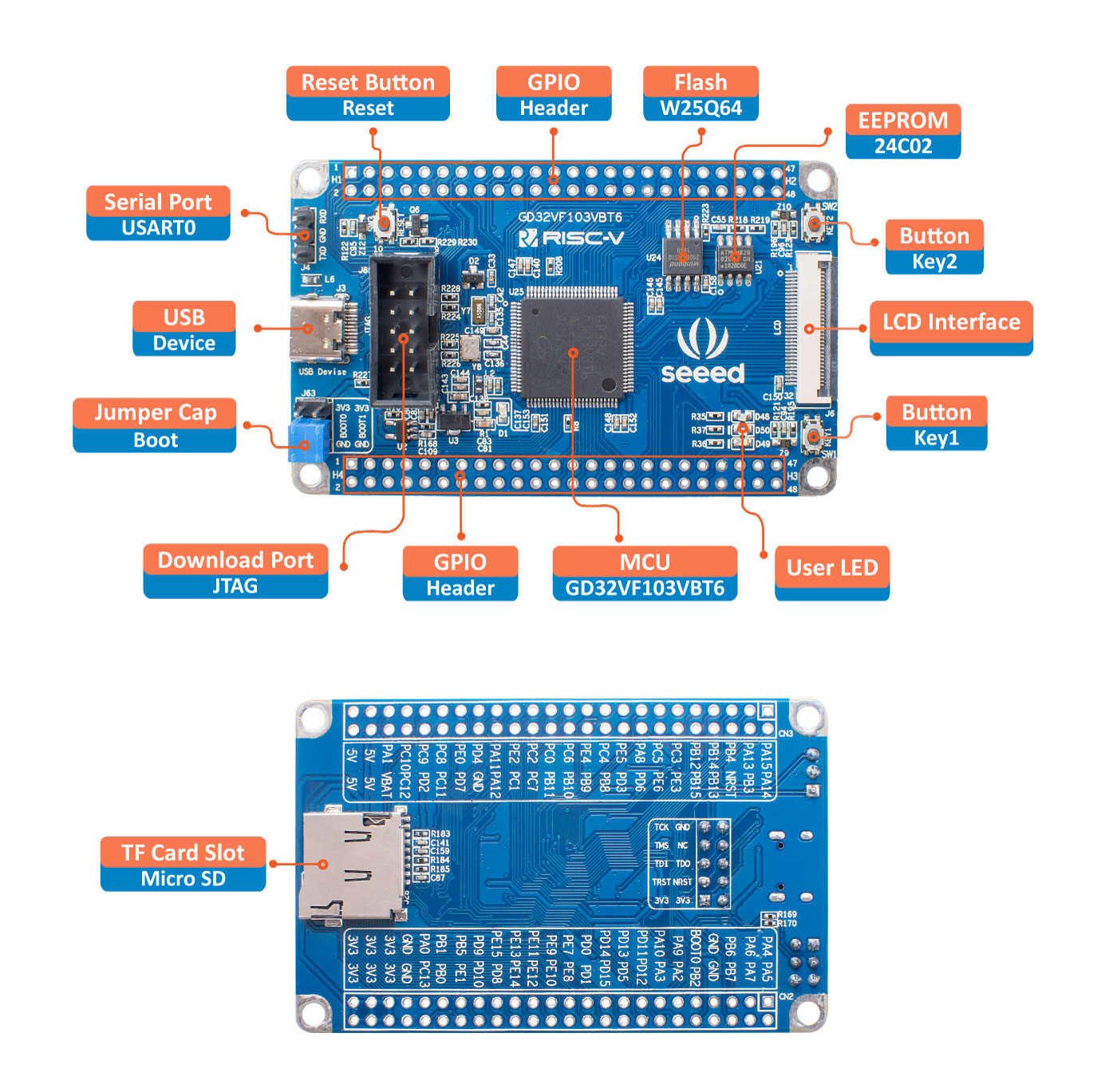
SeeedStudio GD32 RISC-V Dev Board is based on GD32VF103VBT6 MCU which can run at up to 108MHz. GD32VF103 device is a 32-bit general-purpose microcontroller based on the RISC-V core, it provides128 KB on-chip Flash memory and 32 KB SRAM memory. Meanwhile, it provides a wealth of interface resources: 5x U(S)ART, 2 x I2C, 3 x SPI, 2 x I2S, 2 x CAN2.0, 1 x USBFS.
We break out all the I/O Pins(80 GPIOs in total) of GD32VF103, which will meet your diverse development needs. With the onboard 8MB flash and 256Byte EEPROM, you can implement more complex applications. Moreover, we provide a wealth of peripheral resources on the development board, including an LCD, a type c USB port, a TF card slot, two user buttons, and three user LEDs.
SeeedStudio has been actively involved in the RISC-V software ecosystem. We support the PlatformIO IDE and the Arduino framework for Seeedstudio GD32. You can either develop with the Arduino API you are familiar with or copy your existing Arduino applications and directly compile and run them.
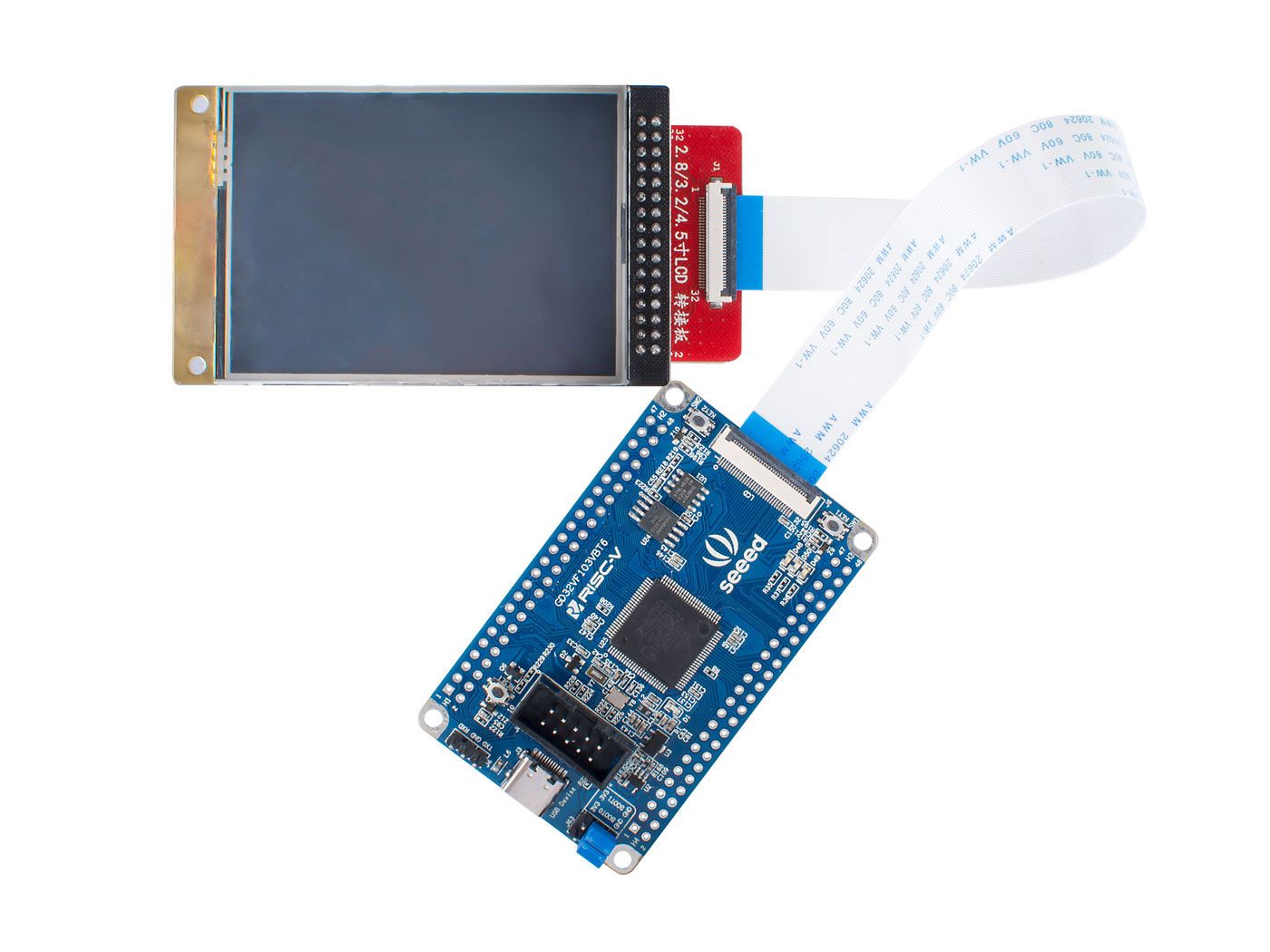
In addition, with this product, we have brought surprises to the developers who are interested in RISC-V, We support Seeed_Arduino_LCD for this product, which is a lightweight GUI based on Bodmer’s TFT_eSPI.You can use the TFT_eSPI API to develop your own products, and you can take applications based on TFT_eSPI and run them directly.
Features
GD32VF103VBT6 RISC-V MCU @108MHz
128KB on-chip Flash + 8MB on-board Flash
LCD Interface: 16-bit 8080 interface and SPI touch screen control interface
USB Type C
GUI support
Hardware Overview
The Seeed Studio development kit is available for pre-order on the Seeedstudio product page for $15.90. The product availability is scheduled for Nov 14th, 2019. The SeeedStudio GD32 RISC-V Dev Board can also be purchased individually without necessarily paying for the whole kit. The dev board is available for pre-order for $6.90, with an estimated availability for Nov 18th, 2019.
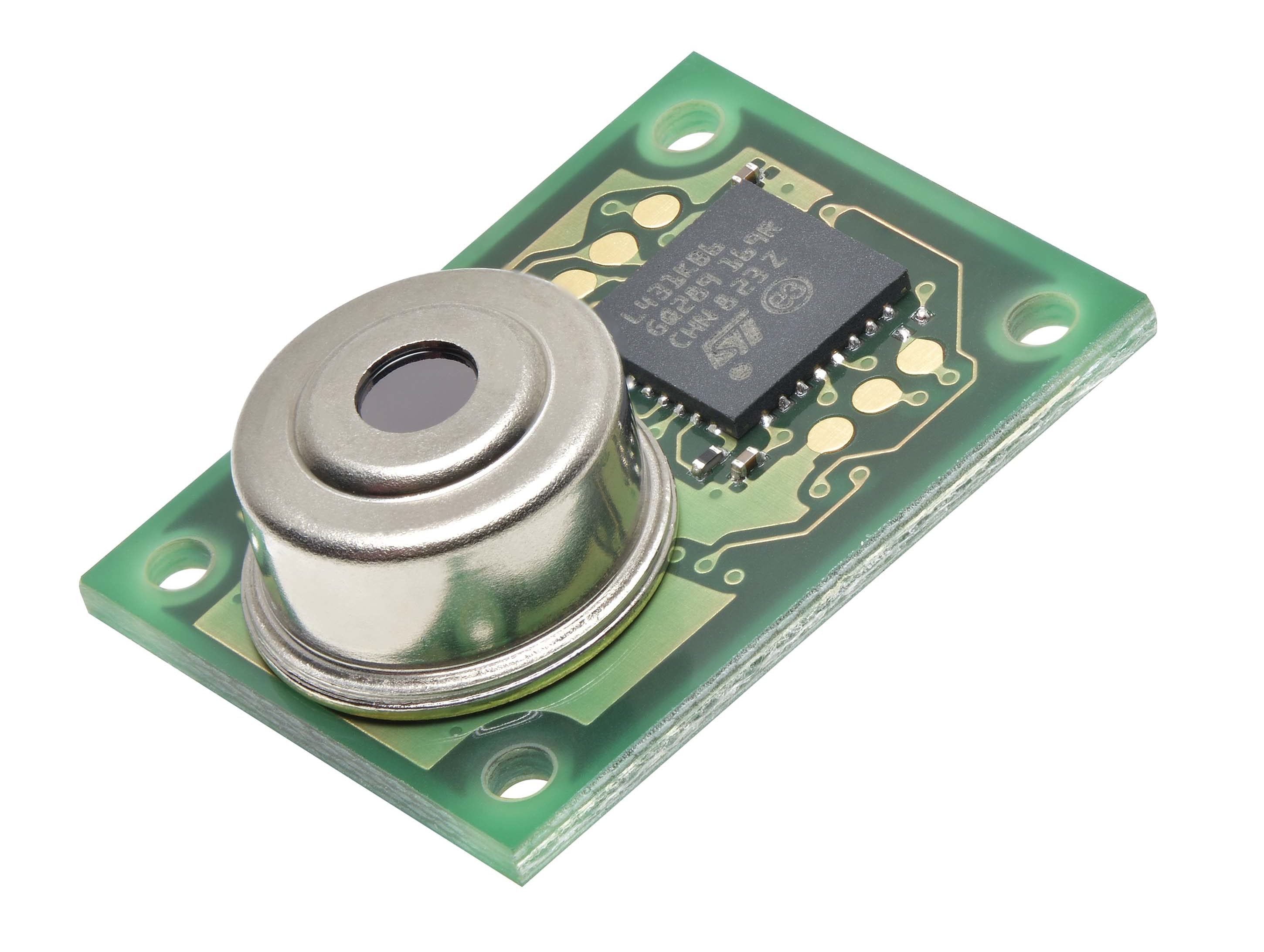
Omron Electronic Components has added a wide angle 32 x 32 element version of its D6T MEMS Thermal Sensors, offering the widest field of view that Omron has ever delivered. The new Omron D6T-32L-01A can view across 90.0° by 90.0°, able to encompass a wide area such as a whole room from a single point. This high performance sensor offers contactless measurement of temperatures of 0-200ºC in ambient temperatures of -10-70ºC.
The D6T-32L is one of three new D6T variants announced by Omron. Applications where a more restricted field of view is needed can be fulfilled by the 1×8 D6T-8L-09H and the 4×4 D6T-44L-06H, offering 54.5° x 5.5° and 44.2° by 45.7° respectively. These two devices offer contactless temperature measurement between 5-200ºC at ambient temperatures of 5-45ºC.
Gabriele Fulco, European Product Manager, Omron, said:
“The new additions to the D6T sensor range open up a great range of new applications. From the detection of abnormal temperatures in industrial equipment on the production line to monitoring of food and other temperatures in the kitchen, the D6T can make a valuable contribution to safety – identifying potential problems before they become major hazards.
“This can not only save lives but also costs, allowing preventative maintenance to be undertaken in a timely manner. People detection remains a further key application area, and the new sensors are able to detect the presence and location of people in a space more accurately and reliably than ever.”
Omron D6T MEMS thermal sensors are based on an IR sensor which measures the surface temperature of objects without touching them using a thermopile element that absorbs radiated energy from the target object. Incorporating a MEMS thermopile, custom designed sensor ASIC and signal processing microprocessor and algorithm into tiny package, the D6T is believed to offer the highest signal-to-noise ratio (SNR) in the industry.
It converts the sensor signal to a digital temperature output giving a straightforward interface to a microcontroller. The space saving design of the D6T, at only 14x8x8.93mm for the largest 32 x 32 element version, makes it exceptionally well suited to temperature detection in a wide range of IoT and other embedded applications.
Recent campaigns around environment pollution helped increase the awareness around it with more people beginning to monitor their pollution footprint while also paying attention to the quality of air they breathe in. Different countries and communities have now several Air quality monitoring solutions deployed in strategic locations but there are times where you as an individual will have the desire for your own personal air quality monitoring solution to monitor the quality of air in your immediate vicinity. For today’s tutorial, we will look at how you can build a DIY personal air quality monitoring solution to monitor the quality of air around you.
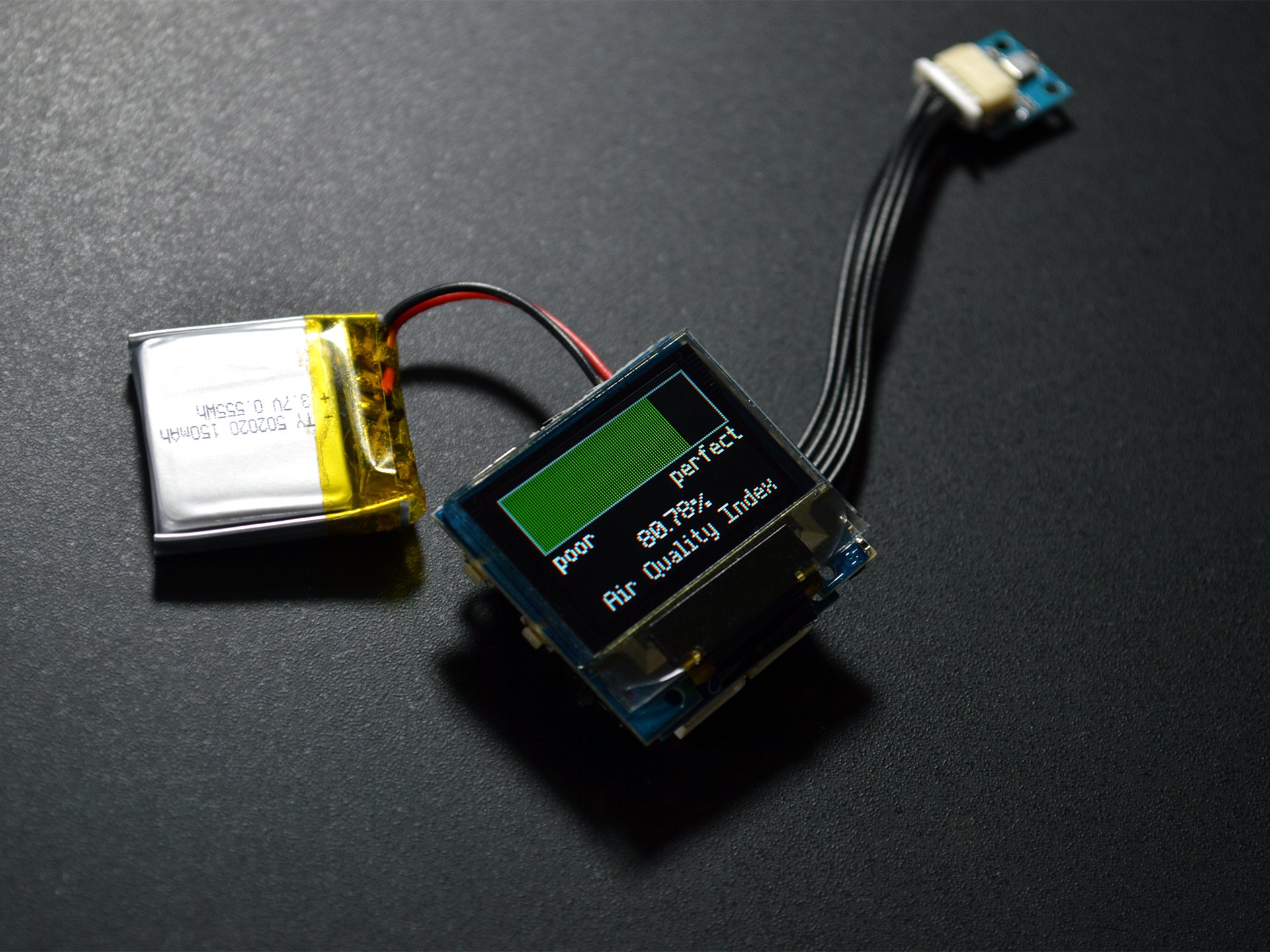
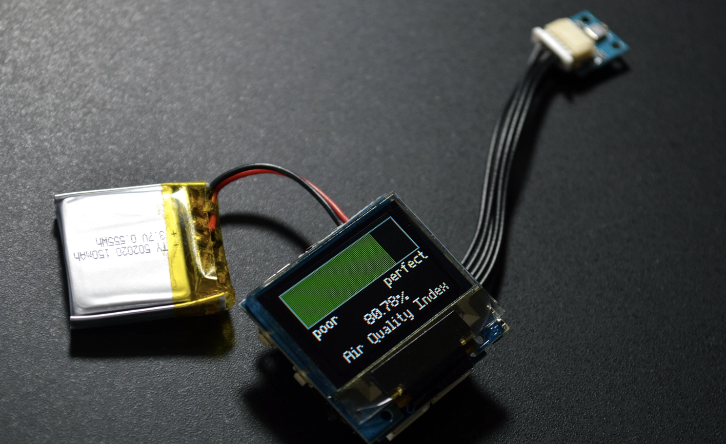
While there are several attempts at Air quality monitoring on the internet, today’s project will chronicle Zachary Lee‘s project because it provides a portable, battery powered, intuitive solution. The project makes use of an air quality sensor from TinyCircuits called the VOC whisker along with a TinyScreen+ which is used to display the air quality index as a bar, and a LiPo battery to power the entire system.
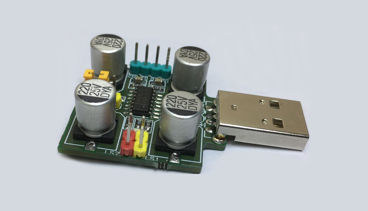
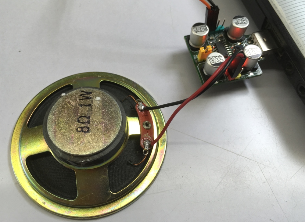
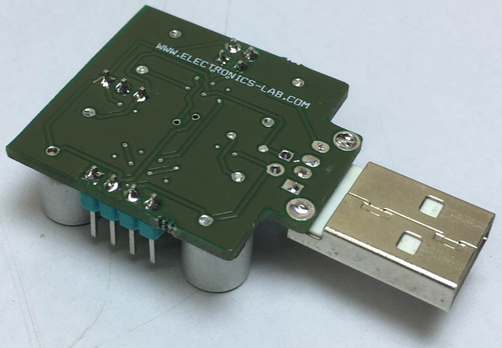
USB powered mini speaker amplifier is conveniently powered by USB and it is simple to set up. USB powered speakers are convenient for listening to your media while at home or on the go. Conventional computer speakers that require an electrical outlet to work can be prohibitive because they force you to be close to the power supply at all times. This audio amplifier is directly connected to a USB port and to the the input signal and you have real high quality sound output from mini speakers or headphone. It is class AB amplifier can drive 16 to 32 ohms load.
USB Powered Audio Amplifier using MAX4298 – [Link]
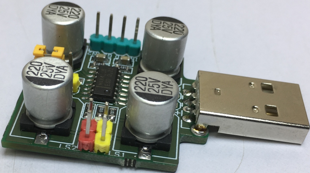
USB powered mini speaker amplifier is conveniently powered by USB and it is simple to set up. USB powered speakers are convenient for listening to your media while at home or on the go. Conventional computer speakers that require an electrical outlet to work can be prohibitive because they force you to be close to the power supply at all times. This audio amplifier is directly connected to a USB port and to the the input signal and you have real high quality sound output from mini speakers or headphone. It is class AB amplifier can drive 16 to 32 ohms load.
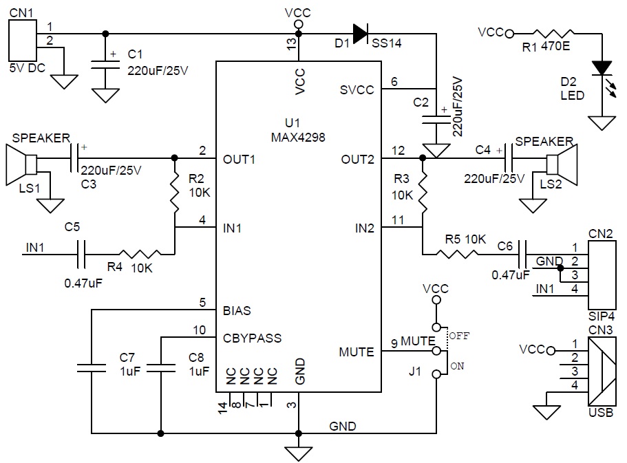
The headphone driver amplifier is a class AB amplifier designed to drive 16Ω loads. The amplifiers have innovative architectures for both the input and output stages to achieve ultra-high PSRR while maintaining rail-to-rail output drive capability. The output stage can drive high capacitive loads encountered when driving long cables used for desktop speakers or headphones.
The MAX4298 is an audio system ICs designed for single +5V applications. The MAX4298 features a stereo headphone driver. The MAX4298 IC designed specifically for harsh digital environments where board space is at a premium and the digital power supply is noisy. The design uses innovative design techniques to achieve ultra-high power-supply rejection across the audio signal band while, at the same time, delivering a high-current Rail-to-Rail output drive capability. The chip is designed to drive highly capacitive loads that may be encountered when driving long cables to a remote load such as desktop/notebook headphones or speakers. These devices are fully compliant with PC99 standards.
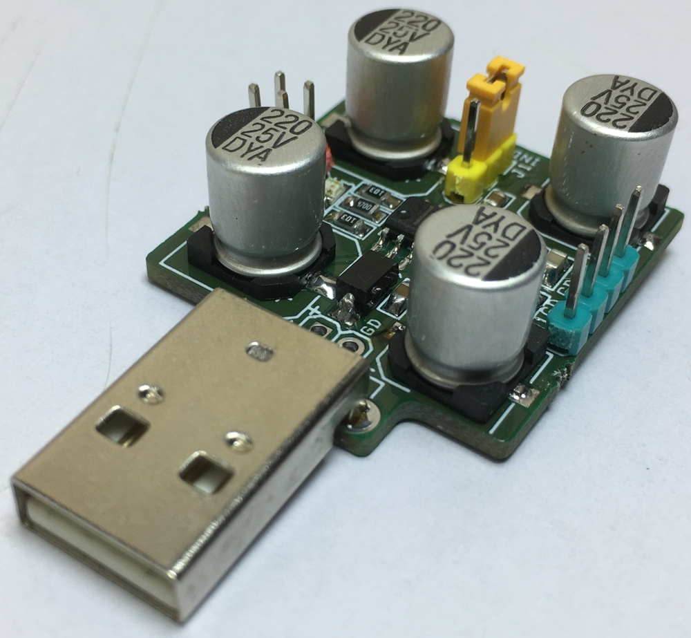
The amplifiers exhibit 115dB of DC power-supply rejection and 80dB at 100kHz. The output amplifiers are capable of driving a 1.5VRMS signal into a 10-kilohm load with 0.0008% THD+N. They can also drive 32Ω headphones to 1.2VRMS with 0.02% distortion.
The MAX4298 has short-circuited current protection on all outputs. They also have a thermal shutdown function designed to protect the chip from junction temperatures in excess of +150°C that may arise from temporary short circuits or operation beyond the power dissipation limit of the package. The driver amplifier outputs limit at around ±220mA.
Features
Supply USB Power 4.5V to 5.5V
Ultra-High PSRR Stereo Headphone Driver
93dB typ PSRR at 20kHz Operates Directly from Noisy Digital Supplies
Clickless/Popless Power Up, Power Down, Mute and Unmute
PC99 Compliant Output Drivers:
Better than 1VRMS Output into 16Ω Load and 1.5VRMS and 0.0008% THD+N into 10kΩ Load
Recent campaigns around environment pollution helped increase the awareness around it with more people beginning to monitor their pollution footprint while also paying attention to the quality of air they breathe in. Different countries and communities have now several Air quality monitoring solutions deployed in strategic locations but there are times where you as an individual will have the desire for your own personal air quality monitoring solution to monitor the quality of air in your immediate vicinity. For today’s tutorial, we will look at how you can build a DIY personal air quality monitoring solution to monitor the quality of air around you.
While there are several attempts at Air quality monitoring on the internet, today’s project will chronicle Zachary Lee‘s project because it provides a portable, battery-powered, intuitive solution. The project makes use of an air quality sensor from TinyCircuits called the VOC whisker along with a TinyScreen+ which is used to display the air quality index as a bar, and a LiPo battery to power the entire system.
The VOC Whisker is essentially a breakout board of the BME680 that allows you to monitor temperature, pressure, humidity, and Volatile Organic Compounds all at once. By its ability to measure VOC (Volatile Organic Compounds) levels, the VOC Whisker provides us with the required sensor to measure several carbon-based pollutants which when we are overexposed to, could lead to increased rates of allergies, respiratory disease, and various types of cancer.
Some of the most dangerous of the VOC’s that can be monitored with VOC whisker include:
Benzene (commonly found in cigarettes, paint, and gasoline and is classified as a human carcinogen by the CDC)
Formaldehyde (found in many glues, resins, foams, plywood, and cigarettes. It has been linked to brain cancer, leukemia and is one of the top 10 allergens)
Styrene (Sweet smelling neurotoxin and carcinogen found in many plastics, with high concentration levels in styrofoam)
While the VOC whisker may not be able to measure the concentration level of each of the VOC’s in existence, it is able to measure the total quantity of VOC’s in the environment and give the index of the quality of air in that environment.
Asides it super small form factor and the incredible amount of parameters it can measure, some of the other features of whisker include;
Digital interface I²C (up to 3.4 MHz) and SPI (3 and 4 wire, up to 10 MHz)
Operating range -40 – +85°C, 0-100 % r.H., 300-1100 hPa
Humidity, Pressure, Gas sensor can be independently enabled / disabled
RoHS compliant, halogen-free, MS
3.0V – 5.5V Operating Voltage
Low power (0.15 µA in sleep mode)
The VOC Whisker is also compatible with TinyCircuit’s TinyShield which makes it easy to connect it to other TinyCircuit products as it incorporates level shifting along with a local power supply to ensure proper and safe operation.
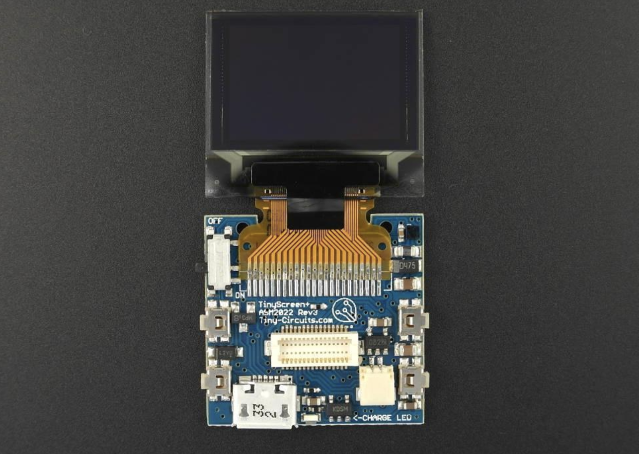
Another major component used in this project is the which doubles as the processor and the display. The TinyScreen+ is a combination of the TinyScreen shield from TinyCircuits (makers of TinyDuino), with an Atmel SAMD21 32-bit ARM processor (the same one used in the Arduino Zero), a USB port, power management IC/circuitry, and battery charger to get a super small, all-in-one, powerful OLED development platform. It retains the standard TinyShield expansion port which allows it for use of all of TinyCircuit’s current shields including whiskers and uses the same TinyScreen library inside the Arduino IDE with most TinyScreen examples working without with the TinyScreen+ without any modification.
At the end of today’s project, you would know not only how to build a personal air quality meter, but also the use of several awesome TinyCircuit components in your projects.
Required Component
The following components are required to build this project;
All of these components can be bought from TinyCircuits store or via the links attached to them.
Schematics
A good thing about TinyCircuit and the TinyShield is how most of the products are designed to snap into the shield, reducing the size of the project and eliminating the need to connect jumper wires from one place to the other.
Connect the Whisker Adapter TinyShield to the TinyScreen+ and connect the VOC Whisker to port 0 on the Whisker Adapter TinyShield via the Whisker cable such that the setup looks like the image above.
The battery should also be connected to it’s port on the TinyScreen+.
Preparing the Arduino IDE
If you have used products from TinyCircuits with the Arduino IDE in the past then you can skip this section but If this is the first time you will need to do some configuring of the Arduino IDE so it recognizes and is able to program the TinyScreen+ correctly. The configuration involves installing the TinyCircuits Core/Board support for the Arduino IDE. Follow the steps below to get this done.
1. Ensure you are running the latest official version of the Arduino IDE. You can download the latest version from their website.
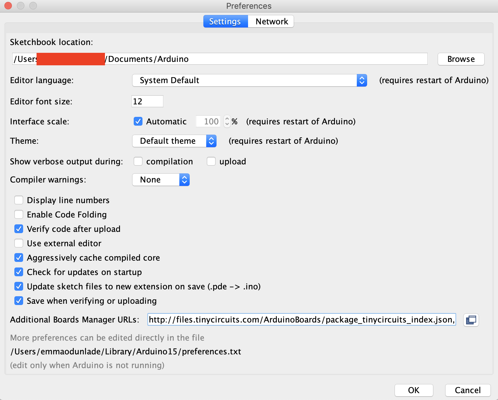
2. Open the preferences window from the Arduino IDE. Go to File > Preferences
3. On the preferences window, locate the “Additional Board Manager URLs” text box and enter http://files.tinycircuits.com/ArduinoBoards/package_tinycircuits_index.json into the field as shown below. As you may have other URLs there already, separate the URLs from each other using a comma (“,”) and click OK when done.
Enter the TinyCircuits Board URL
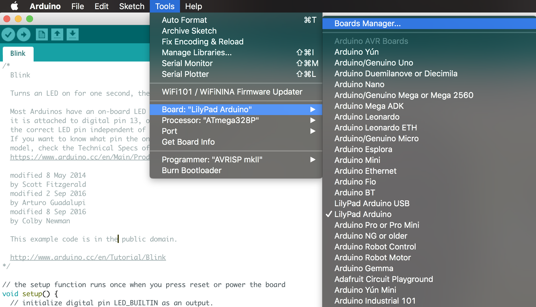
4. Next, open the Arduino board manager. Go to tools > Boards > Boards manager
Launch Board Manager
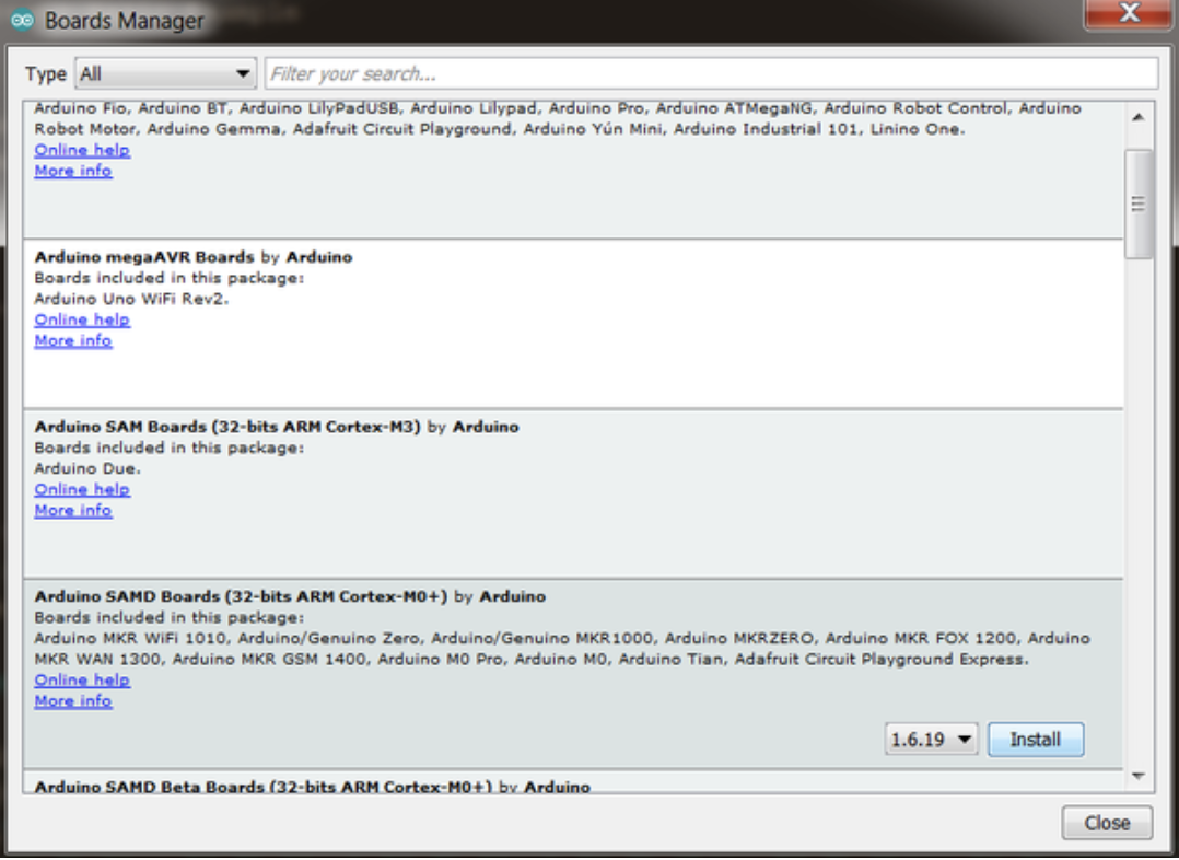
5. When the board manager opens, enter Arduino SAMD Boards into the search bar and scroll to the bottom, you will see “Arduino SAMD Boards (32-bits ARM Cortex-M0+) by Arduino”, select it and if not already installed and click on install.
6. In the same Board Manager window, enter TinyCircuits into the search bar and scroll down to select and install the TinyCircuits SAMD Boards.
7. With the above done, you should now have the TinyCircuit boards listed with the other boards on the IDE. Next, we need to install the TinyScreen Library. Go to Sketch->Include Library->Manage Libraries 8. Search for “TinyScreen”, select and install it.
The TinyScreen library can also be installed manually by downloading it from the attached link and extracting its content into the Arduino libraries folder.
With these done, the Arduino IDE is now ready to be used in programming the TinyScreen+.
Code
The code for today’s project is quite straight forward. We will use the raw VOC readings from the BME680 to calculate and graph (using a progress bar) the Air Quality Index.
As already mentioned, the code will be developed using the Arduino IDE and in addition to the TinyScreen Library which we installed earlier, we will use a few other libraries to reduce the amount of work that needs to be done in developing the sketch for the project. Some of these libraries will include; the Adafruit BME680 library, the Adafruit Sensor Library, the TinyAnimation library, and the Arduino Wire library. The wire library facilitates communication with I2C devices and will be used to facilitate communication with the VOC Whisker, while the Adafruit BME280 and Adafruit_Sensor Library will be used to interface with the Whisker since the VOC whisker is based on the BME680. The TinyAnimation library is used along the TinyScreen library to create the progress bar and update the data on the display as its changes. All of these libraries can be installed via the Arduino Library Manager or via the link attached to them.
As usual, I will do a quick “run” through the code to explain some of the key concepts.
We start, as usual, by including all the libraries required for the sketch.
// This library is used for communication with I2C devices, such as the BME680 board
#include <Wire.h>

// This library is used to print sensor values to a TinyScreen
#include <TinyScreen.h>
#include "TinyAnimation.h"

// These libraries are used to interface with the BME680 Sensor
#include "Adafruit_Sensor.h"
#include "Adafruit_BME680.h"
Next, we create an instance of the BME680 library along with a variable to be used in determining the approximate altitude.
#define SEALEVELPRESSURE_HPA (1013.25) // used to find approximate altitude
Adafruit_BME680 bme; // I2C
Next, we create variables that are specific to the TinyScreen display, including an instance of the library, the background and variables to hold what the progress bar should look like for a certain range of values.
Next, we create and initialize a few more variables that are important to the project including; a delayTime variable to specify the intervals between readings, a airQualityGraphic variable to let the user determine if the values are displayed graphically like with the progress bar or just dumped on the display without processing. Several other variables were created and initialized and they all have quite descriptive names so it should be easy to tell what if one stands for.
// Used to control how often sensor values are updated in the main loop()
unsigned long delayTime = 20;
// The power pin for our board, used for digitally writing to output
const int powerPin = 4;
const bool airQualityGraphic = true; // if set to true air quality graphic will be displayed instead of text output of all sensor data
const bool raw = false; // if set to true, raw VOC data will be displayed instead of an airQuality percentage based on that data
const bool displayAlt = false; // if set to true, altitude will be displayed on the TinyScreen+ instead of air quality/raw due to shortage of room. Will not impact serial output.
float airQuality = 0.00;
float allTimeHighest = 0.00;
float highestInRange = 0.00;
float secondHighestInRange = 0.00;
unsigned long highRangeTime = millis();
unsigned long secondRangeTime = millis();
const int MAX = 550000; // theoretical max raw air quality reading. used for a small percentage of the air quality calculation
const int RANGE_DURATION = 18; // 50% of the VOC portion of the air quality reading will be based on the difference between the current value and the extremes of the last RANGE_DURATION hours
Next, we write the void setup() function.
We start the function by initializing serial communication (with SerialUSB being the TinyCircuit library version of the “Serial” identifier in Arduino) so we can use the serial monitor for debugging.
void setup() {
SerialUSB.begin(9600); // Bandwidth for our communication
Next, we set the pinMode of the power pin of the sensor after which we initialize I2C wire communication, and set the port of the TinyScreen to which the VOC Whisker is connected.
// We want to see Digital Output from the sensor
pinMode(powerPin, OUTPUT);
digitalWrite(powerPin, HIGH);
Wire.begin();
selectPort(0); // The adapter board has 4 different ports (0-3),
// make sure your software matches the setup!
Next, we initialize the display; setting its brightness level, font, and text color.
// This is the setup used to initialize the TinyScreen's appearance
display.begin();
display.setBrightness(15);
display.setFlip(true);
display.setFont(thinPixel7_10ptFontInfo);
display.fontColor(TS_8b_White, background);
We set the cursor to a coordinate at the middle of the display and print a welcome message.
// Set the cursor to the following coordinates before it prints "BME680 Test"
display.setCursor(7, 54);
display.print("Air Quality Index");
Next, we check the status of the BME680 t0 see if it is properly connected. If it is, the system proceeds to set up oversampling and initialize filters for each of the parameters to be monitored but if it’s not, the processor is halted using a while(1) loop.
// If the bme sensor is not found, throw statement and stop program
// If you end up here, check to make sure your value in selectPort() is correct!
if (!bme.begin(0x76)) {
display.setCursor(12, 12);
display.print("No Sensor!"); // Printed to TinyScreen
SerialUSB.println("Could not find a valid BME680 sensor, check wiring!"); // Printed to Serial Monitor
while (1); // loop forever, because the rest of the program means nothing without the sensor
}
// Set up oversampling and filter initialization
bme.setTemperatureOversampling(BME680_OS_8X);
bme.setHumidityOversampling(BME680_OS_2X);
bme.setPressureOversampling(BME680_OS_4X);
bme.setIIRFilterSize(BME680_FILTER_SIZE_3);
bme.setGasHeater(320, 150); // 320*C for 150 ms
terriblebar.updateBarEndInfo(); // Apply the letters to the screen once so we don't have to every tick
}
Next, we write the void loop() function.
We start the function by reading the BME680 and based on the readings obtained, we compare and calculate the Air Quality value.
void loop() {
if (! bme.performReading()) {
SerialUSB.println("Failed to perform reading :(");
return;
}
validateRange();
compareAirQuality();
calculateQuality();
The value is then converted into a percentage and categorized, based on the percentage, into terrible, poor, average, good, or excellent, with excellent being a percentage between 80 – 100 and terrible being anything below 20. Based on the category the reading falls into, the right progress bar and the value is displayed on the on the TinyScreen+.
The remaining part of the sketch are the functions that were called within the setup and loop() functions including; the validateRange() function, CalculateQuality(), compareAirQuality(), and selectPort(). The code for these functions contain variables with very descriptive names and it should be easy to follow to understand what each one does.
// **This function is necessary for all Whisker boards attached through an Adapter board**
// Selects the correct address of the port being used in the Adapter board
void selectPort(int port) {
Wire.beginTransmission(0x70); //I2C
Wire.write(0x04 + port);
Wire.endTransmission();
}
void compareAirQuality()
{
float temp = (bme.gas_resistance/1000);
if(temp>allTimeHighest)
{
allTimeHighest = temp;
}
if(temp>highestInRange)
{
secondHighestInRange = highestInRange;
secondRangeTime = highRangeTime;
highestInRange = temp;
highRangeTime = millis();
}
}
void validateRange()
{
if(((((millis()-highRangeTime)/1000)/60)/60)>RANGE_DURATION)
{
highestInRange = secondHighestInRange;
}
if(((((millis()-secondRangeTime)/1000)/60)/60)>RANGE_DURATION)
{
secondHighestInRange = bme.gas_resistance/1000;
}
}
void calculateQuality()
{
float raw = (bme.gas_resistance/1000);
float rawHumidity = bme.readHumidity();
float shortTermQuality = 1-((highestInRange-raw)/highestInRange);
float longTermQuality = 1-((allTimeHighest-raw)/allTimeHighest);
float theoreticalQuality = 1-((MAX-raw)/MAX);
float humidityIndex = 1-(abs(rawHumidity-40.00)/100); // absolute difference between current humidity and optimal humidity
airQuality = (0.75*((shortTermQuality*0.5)+(longTermQuality*0.25)+(theoreticalQuality*0.25))+(humidityIndex*0.25))*100.00;
SerialUSB.print("airQuality: ");
SerialUSB.print(airQuality);
SerialUSB.println("%");
}
The complete code for the project is provided below and also attached (along with all the libraries used) in the zip file under the download section.
/*************************************************************************
BME680 Air Quality Index Example:
Calculates and graphs an Air Quality Index (AQI) based on the
raw VOC readings of the BME680. Note that the air quality metric
becomes slightly more accurate the longer the sketch is run
without interruption. This is because 40% of the calculation is
based on the ratio between current raw air quality and the
extreme levels of air quality in the past 18 hours.
Hardware by: TinyCircuits
BME680 Library by: Adafruit
Code by: Zachary Lee for TinyCircuits
Initiated: Mon. 08/05/19
************************************************************************/
// This library is used for communication with I2C devices, such as the BME680 board
#include <Wire.h>
// This library is used to print sensor values to a TinyScreen
#include <TinyScreen.h>
#include "TinyAnimation.h"
// These libraries are used to interface with the BME680 Sensor
#include "Adafruit_Sensor.h"
#include "Adafruit_BME680.h"
// Global Sensor Variables
#define SEALEVELPRESSURE_HPA (1013.25) // used to find approximate altitude
Adafruit_BME680 bme; // I2C
// TinyScreen Global Variables
TinyScreen display = TinyScreen(TinyScreenPlus);
int background = TS_8b_Black; // sets the background color to black
PercentBarHorizontal terriblebar(display, 2, 2, 94, 28, TS_8b_Gray, TS_8b_DarkRed, TS_8b_White, 0, "poor", "perfect", true);
PercentBarHorizontal poorbar(display, 2, 2, 94, 28, TS_8b_Gray, TS_8b_Red, TS_8b_White, 0, "poor", "perfect", true);
PercentBarHorizontal averagebar(display, 2, 2, 94, 28, TS_8b_Gray, TS_8b_Yellow, TS_8b_White, 0, "poor", "perfect", true);
PercentBarHorizontal goodbar(display, 2, 2, 94, 28, TS_8b_Gray, TS_8b_Green, TS_8b_White, 0, "poor", "perfect", true);
PercentBarHorizontal excellentbar(display, 2, 2, 94, 28, TS_8b_Gray, TS_8b_DarkGreen, TS_8b_White, 0, "poor", "perfect", true);
// Used to control how often sensor values are updated in the main loop()
unsigned long delayTime = 20;

// The power pin for our board, used for digitally writing to output
const int powerPin = 4;
const bool airQualityGraphic = true; // if set to true air quality graphic will be displayed instead of text output of all sensor data
const bool raw = false; // if set to true, raw VOC data will be displayed instead of an airQuality percentage based on that data
const bool displayAlt = false; // if set to true, altitude will be displayed on the TinyScreen+ instead of air quality/raw due to shortage of room. Will not impact serial output.
float airQuality = 0.00;
float allTimeHighest = 0.00;
float highestInRange = 0.00;
float secondHighestInRange = 0.00;
unsigned long highRangeTime = millis();
unsigned long secondRangeTime = millis();
const int MAX = 550000; // theoretical max raw air quality reading. used for a small percentage of the air quality calculation
const int RANGE_DURATION = 18; // 50% of the VOC portion of the air quality reading will be based on the difference between the current value and the extremes of the last RANGE_DURATION hours
void setup() {
SerialUSB.begin(9600); // Bandwidth for our communication
// Print to Serial Monitor
// You can pass flash-memory based strings to SerialUSB.print() by wrapping them with F().
// This means you're using flash memory instead of RAM to print stuff
// while (!SerialUSB);
SerialUSB.println(F("BME680 test"));
// We want to see Digital Output from the sensor
  pinMode(powerPin, OUTPUT);
  digitalWrite(powerPin, HIGH);

  Wire.begin();
  selectPort(0); // The adapter board has 4 different ports (0-3),
  // make sure your software matches the setup!
// This is the setup used to initialize the TinyScreen's appearance
  display.begin();
  display.setBrightness(15);
  display.setFlip(true);
  display.setFont(thinPixel7_10ptFontInfo);
  display.fontColor(TS_8b_White, background);
// Set the cursor to the following coordinates before it prints "BME680 Test"
  display.setCursor(7, 54);
  display.print("Air Quality Index");
// If the bme sensor is not found, throw statement and stop program
  // If you end up here, check to make sure your value in selectPort() is correct!
  if (!bme.begin(0x76)) {
    display.setCursor(12, 12);
    display.print("No Sensor!");  // Printed to TinyScreen
    SerialUSB.println("Could not find a valid BME680 sensor, check wiring!"); // Printed to Serial Monitor
    while (1); // loop forever, because the rest of the program means nothing without the sensor
  }
  // Set up oversampling and filter initialization
  bme.setTemperatureOversampling(BME680_OS_8X);
  bme.setHumidityOversampling(BME680_OS_2X);
  bme.setPressureOversampling(BME680_OS_4X);
  bme.setIIRFilterSize(BME680_FILTER_SIZE_3);
  bme.setGasHeater(320, 150); // 320*C for 150 ms

  terriblebar.updateBarEndInfo(); // Apply the letters to the screen once so we don't have to every tick
}
// Forever looping the following logic
void loop() {
  if (! bme.performReading()) {
    SerialUSB.println("Failed to perform reading :(");
    return;
  }
  validateRange();
  compareAirQuality();
  calculateQuality();
  airQuality /= 100;
  if(airQuality*100 < 20) // terrible
  {
     terriblebar.tick(airQuality);
  }
  else if(airQuality*100 < 40 && airQuality*100 >=20) // poor
  {
     poorbar.tick(airQuality);
  }
  else if(airQuality*100 < 60 && airQuality*100 >=40) // average
  {
     averagebar.tick(airQuality);
  }
 else if(airQuality*100 < 80 && airQuality*100 >=60) // good
  {
     goodbar.tick(airQuality);
  }
 else //(airQuality*100 >=80) excellent
  {
     excellentbar.tick(airQuality);
  }
  airQuality *= 100;
  delay(delayTime); // How often values are updated and printed
}
// **This function is necessary for all Whisker boards attached through an Adapter board**
// Selects the correct address of the port being used in the Adapter board
void selectPort(int port) {
  Wire.beginTransmission(0x70); //I2C
  Wire.write(0x04 + port);
  Wire.endTransmission();
}

void compareAirQuality()
{
  float temp = (bme.gas_resistance/1000);
  if(temp>allTimeHighest)
  {
    allTimeHighest = temp;
  }
   if(temp>highestInRange)
  {
    secondHighestInRange = highestInRange;
    secondRangeTime = highRangeTime;
    highestInRange = temp;
    highRangeTime = millis();
  }
}

void validateRange()
{
  if(((((millis()-highRangeTime)/1000)/60)/60)>RANGE_DURATION)
  {
    highestInRange = secondHighestInRange;
  }
  if(((((millis()-secondRangeTime)/1000)/60)/60)>RANGE_DURATION)
  {
    secondHighestInRange = bme.gas_resistance/1000;
  }
}

void calculateQuality()
{
  float raw = (bme.gas_resistance/1000);
  float rawHumidity = bme.readHumidity();
  float shortTermQuality = 1-((highestInRange-raw)/highestInRange);
  float longTermQuality = 1-((allTimeHighest-raw)/allTimeHighest);
  float theoreticalQuality = 1-((MAX-raw)/MAX);
  float humidityIndex = 1-(abs(rawHumidity-40.00)/100); // absolute difference between current humidity and optimal humidity
  airQuality = (0.75*((shortTermQuality*0.5)+(longTermQuality*0.25)+(theoreticalQuality*0.25))+(humidityIndex*0.25))*100.00;
  SerialUSB.print("airQuality: ");
  SerialUSB.print(airQuality);
  SerialUSB.println("%");
}
Uploading the Code
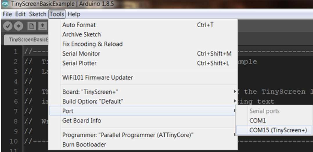
Go over your connections once again to ensure everything is as it should be. Verify the code and when done, connect the TinyScreen+ to your computer. Go to tools -> Boards and select TinyScreen+ as shown in the image below.
Select the Port to which the tinyScreen+ is connected and hit the upload button.
Select the Port
Demo
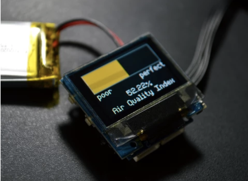
After the Sketch upload is complete you should see the device display the quality of air around it. To test it, you can move into a construction site or an open field for instance and examine the difference between the Air Quality index for both environments. An air quality value very close to the poor mark means it’s best if the user vacates that vicinity, while a value closer to the perfect mark means that location/environment is one of the “best place to be” on earth.
Demo
That’s it for this tutorial and thanks for reading. As usual, feel free to reach out to me via the comment section if you have any difficulties replicating this.
We’ve covered some mini laptops in past with 7″ to 9″ displays, but most came with a fairly high price due to the somewhat high specs with Amber Lake or Gemini Lake processors, 8GB+ RAM, 128GB+ storage, etc… meaning in most cases you’d have to pay between $500 and $1,000 for such a small device.
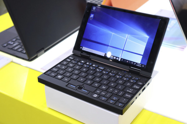
If you’d like to buy such a mini laptop for simple tasks but don’t quite want to spend that much money on it, Pretech F700Mi Mini laptop with a 7″ display should be much cheaper thanks to an Intel Atom X5-Z8350 quad-core processor, 4GB RAM, and 32GB to 128GB storage.
Pretech F700Mi Mini specifications:
SoC – Intel Atom x5-Z8350 quad-core Cherry Trail processor
USB – 1x USB type-C port for power and data only, 1x USB 3.0 port
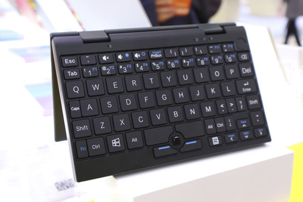
User Input – QWERTY keyboard, optical touchpad, and mouse buttons
Misc – Optional fingerprint sensor
Battery – 5,000 mAh / 3.8V
Dimensions – 181 x 113.6 x 19.6 mm (metal frame)
Weight – 541 mm
This Windows 10 laptop is fanless, and there’s a small grid positioned on the bottom to dissipate the heat. Intel Atom x5-Z8350 processor is a low-end processor found in the $35 Atomic Pi SBC, so the good news is that the Pretech F700Mi Mini should be fairly cheap once it comes out maybe sell around $200-$250 retail in its default configuration.
But obviously don’t expect to use the mini laptop as a laptop replacement with multi-tasking in mind since it will be painfully, but for simple tasks like remote logging over SSH or VNC, it should be just fine at a much lower cost than other mini laptops currently on the market.
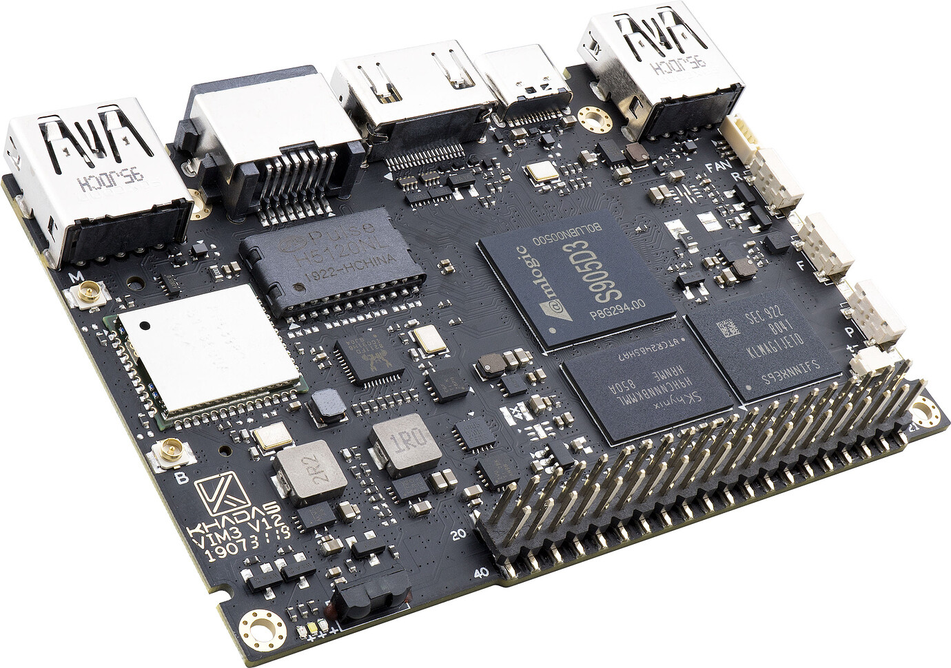
Shenzhen Wesion has unveiled a lite version of the VIM3, called Khadas VIM3L SBC. Designed for HTPC / media center use cases, the VIM3L SBC is based on Khadas VIM3 PCB but replaces the powerful Amlogic A311D processor by Amlogic S905D3 processor, which should function just as good for video playback, but enable much cheaper hardware.
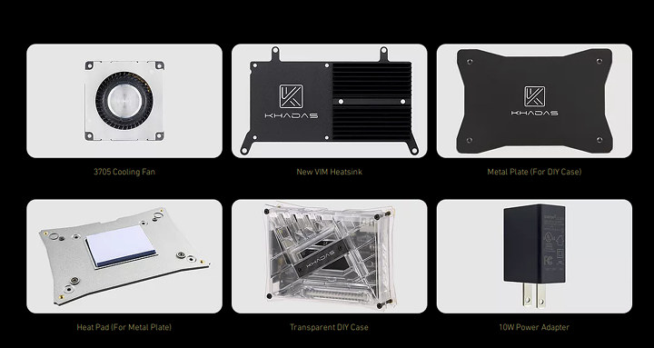
The Khadas VIM3L offers support for the same accessories as the VIM3, like the heatskin, fan, M2X extension board with PoE, 4G, and NVMe SSD support, as well as MIPI-CSI and MIPI-DSI connectors for adding an optional display or camera. There’s also a PCIe (1-lane) connector on the bottom of the board. Regarding cooling, the company states that the S905D3 is capable of operating in passive cooling mode whilst running Android OS. If booting Linux, or 3rd party distros, adding the 3705 Cooling Fan for active cooling is recommended.
The board is not really available yet, but the company has began taking pre-orders for the Khadas VIM3L at discounted prices. They offer either a bare board with Android 9.0 pre-installed ($49.99), or a CoreELEC HTPC kit with enclosure, heatsink, WiFi antennas, and IR remote control ($69.99). Both variants feature Amlogic S905D3 quad-core Cortex-A55 processor as well as 2GB LPDDR4(X) RAM, 16GB eMMC flash, and support 4Kp60 video output and playback with HDR support.
The company will increase the prices with time as follows: September 3-16 (Early Bird) – $49.99 and $69.99 for the board and HTPC kit respectively, September 17 – October 7 for (Punctual Bird)– $54.99 and $74.99, and October 8 and above– $59.99 and $79.99. Note that worldwide shipping is already included in the price, so you don’t need to pay an additional shipping fee as most other companies do. The company will start shipping pre-orders on October 30, 2019.
khadas VIM3L accessories
The latest launch of Khadas VIM3 & VIM3L boards, will make the previous VIM boards become less interesting, and less likely to be used. To this end, it is only appropriate for the company to lower their prices. Khadas VIM board, also called the VIM1, is powered by Amlogic S905X processor, while the VIM2 features Amlogic S912 octa-core processor.
The new prices are as follows: VIM1 Basic, featuring 1GB RAM, 8GB EMMC price has dropped to $44.99 from $54.90, VIM1 Pro featuring 2GB RAM, 16GB EMMC is now $54.99 instead of $69.90, VIM2 Pro featuring 3GB RAM, 32GB EMMC 5.1, AP6398S Wi-Fi, and w/ Bluetooth 5.0 now costs $99.99 instead of $119.90, and VIM2 Max featuring 3GB DDR4, 64GB EMMC 5.1, AP6398S Wi-Fi, w/ Bluetooth 5.0 is now $119.99.
If you are interested in the older boards, you can get VIM1 and VIM2 respectively. For the VIM3L, visit here for more info.
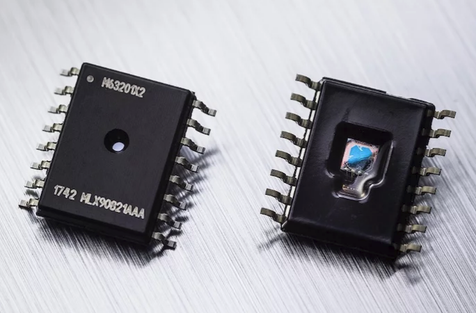
Melexis has designed a relative pressure sensor IC that can operate in and measure very low pressures in automotive applications. The MLX90821 can detect even the smallest vapor leaks—which is a central part of EVAP systems. The device is an SoC (system on a chip) employing MEMS (Microelectromechanical system) technology, an analog signal chain, and digital signal processing to measure fuel vapor pressure over a range of 50 to 700 millibars.
The MLX90821 is a packaged and factory calibrated automotive relative pressure sensor IC with an analog and a SENT output that can be used in applications demanding very low pressures from 50 mbar up to 700 mbar in automotive harsh media applications such as fuel vapor.
The MLX90821 is the ideal solution for measuring very low pressures in applications requiring extended mission profiles when high robustness is needed.
Top features
High accuracy relative pressure sensor with ratiometric analog output or digital SENT output including compensated ±1 °C accurate NTC media temperature information
Large automotive temperature range (-40 °C to 150 °C)
Automotive qualified and automotive diagnostic features (clamping levels, broken track diagnostics, multiple internal fault diagnostics)


 6. In the same Board Manager window, enter TinyCircuits into the search bar and scroll down to select and install the TinyCircuits SAMD Boards.
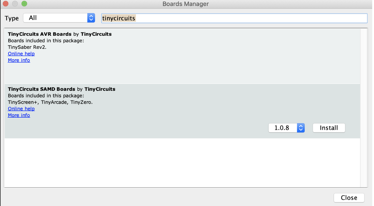 7. With the above done, you should now have the TinyCircuit boards listed with the other boards on the IDE. Next, we need to install the TinyScreen Library. Go to Sketch->Include Library->Manage Libraries
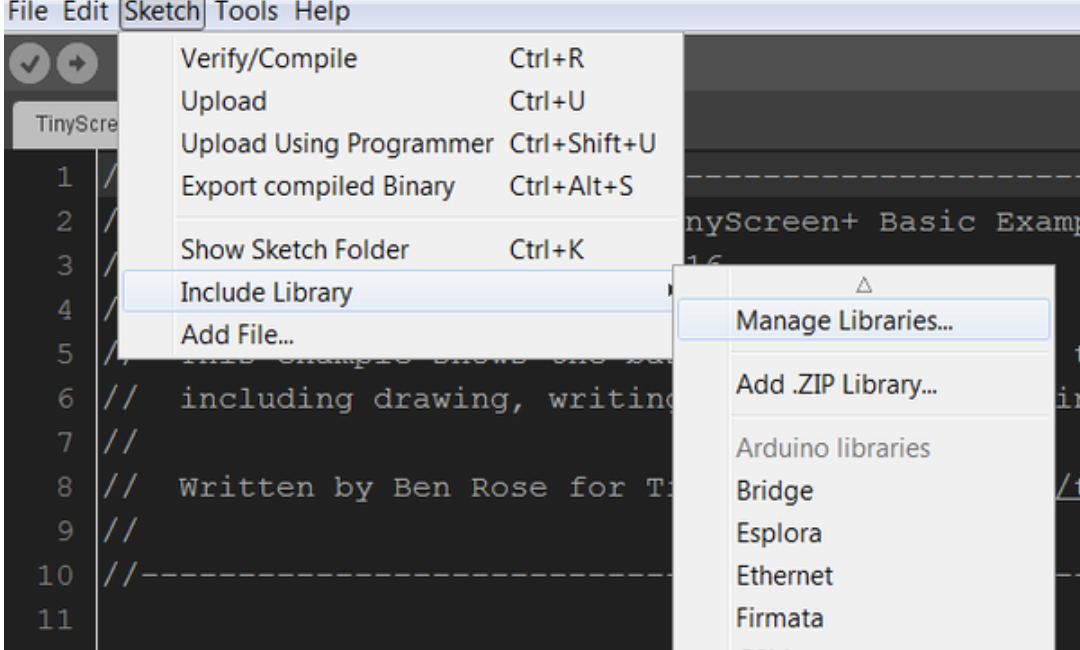 8. Search for “TinyScreen”, select and install it.
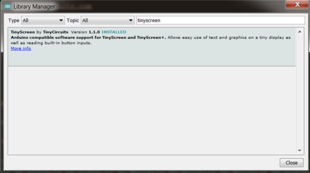 The TinyScreen library can also be installed manually by downloading it from the attached link and extracting its content into the Arduino libraries folder.
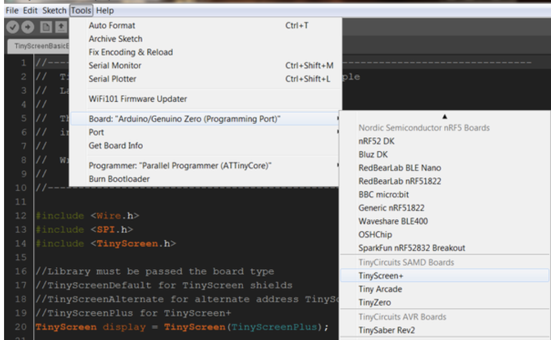 Select the Port to which the tinyScreen+ is connected and hit the upload button.