The Tiny Reflow controller v1 we discussed in the first article uses a LCD display and mostly SMD components and this kind of controller is required to control the heat process in reflow ovens to ensure the right amount of heat is supplied at all stages of the reflow process.
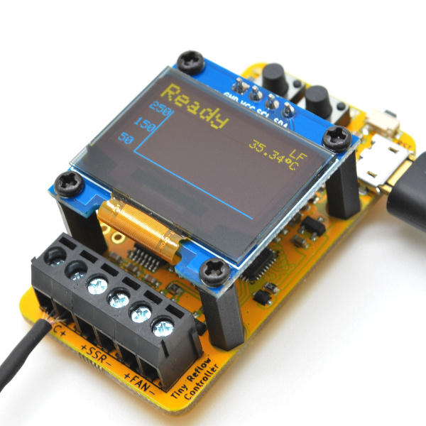
The Tiny Reflow controller v2 unlike the v1, is based on the Atmega328p Microcontroller. It retains the MAX31856 thermocouple interface used in the v1 but comes with a USB-Serial interface chip to facilitate programming, and an OLED LCD instead of the 20×4 LCD display used on the v1. The OLED display ensures more information like the plot of the reflow curve can be provided as feedback to the users to give us a better understanding of the reflow process and state.
David Johnson-Davies published another great mini project. It’s a Timer based on ATtiny402 and was build to demonstrate the low power sleep mode of the microcontroller.
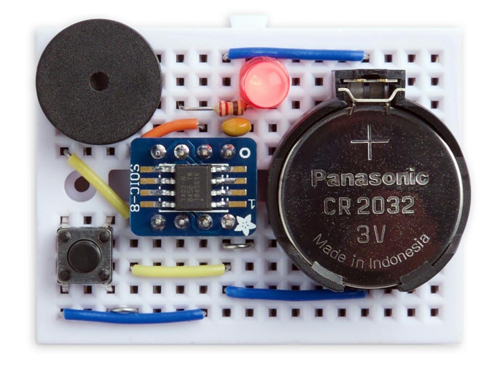
This article describes how to use the new 0-series and 1-series ATtiny microcontrollers in low-power projects, taking advantage of sleep mode to maximise the battery life and avoid the need for an on/off switch. The project is a simple 15-minute timer that flashes an LED once every 2 seconds while it is counting down, and then beeps a piezo buzzer when the time has expired. You could use it as the basis for an egg timer, a bath-overflow alarm, or any other fixed timer application.
ATtiny402 Timer with low power sleep mode – [Link]
The Tiny Reflow controller v1 we discussed in the first article uses a LCD display and mostly SMD components and this kind of controller is required to control the heat process in reflow ovens to ensure the right amount of heat is supplied at all stages of the reflow process.
The Tiny Reflow controller v2 unlike the v1, is based on the Atmega328p Microcontroller. It retains the MAX31856 thermocouple interface used in the v1 but comes with a USB-Serial interface chip to facilitate programming and an OLED LCD instead of the 20×4 LCD display used on the v1. The OLED display ensures more information like the plot of the reflow curve can be provided as feedback to the users to give us a better understanding of the reflow process and state.
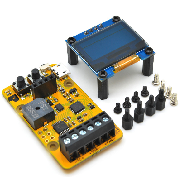
Like the v1, the Tiny Reflow controller v2 also features mostly SMD parts to keep the cost low (manual soldering and left over residue cleaning is time consuming) with the only through hole component being the terminal block (which doesn’t come in SMD type). This helped reduce the form factor/size of the reflow controller to the smallest possible and makes it a controller of choice in space constrained applications. To make the controller easy to power and simplify the design, all components used were streamlined to run on 3.3V voltage level.
The reflow controller v2 encompasses all you will need to control the reflow heat and you only need to connect a K type thermocouple (we recommend those with fiber glass or steel jacket), a Solid State Relay (SSR) (rated according to your oven), and the oven of course, connected to the terminal blocks of the controller.
Some of the highlighted features of the reflow Controller V2 include:
Powered by ATmega328p
MAX31856 thermocouple interface
0.96″ 128×64 OLED LCD yellow and blue color
1 terminal block for driving SSR (through an NPN transistor, 5mA @ 5V output) to control heating element/oven
1 terminal block for driving SSR (through an NPN transistor, 5mA @ 5V output) to control fan
Warning Sounds via Buzzers
ISP pins breakout to facilitate reprogramming
Built-in USB-serial interface for firmware upload and serial interface
Power via a MicroUSB connector with 500mA fuse
Comes with extra 4 pieces of M2*5mm spacer (male-female) and 4 pieces of M2*5mm screws if you decided to mount it on the oven’s front panel
FR4 TG140 PCB with immersion gold (ENIG) finish
RoHS compliant
Required Components
The major components required to build this project include:
ATmega328p microcontroller
MAX31856 thermocouple interface IC
K-Type Thermocouple (Rocket stream recommends those with fiberglass or steel jacket)
0.96″ OLED Display
2 push button
LED
3 (dual port) Terminal Blocks
1 Buzzer
An Oven
External Solid State Relay
A small fan
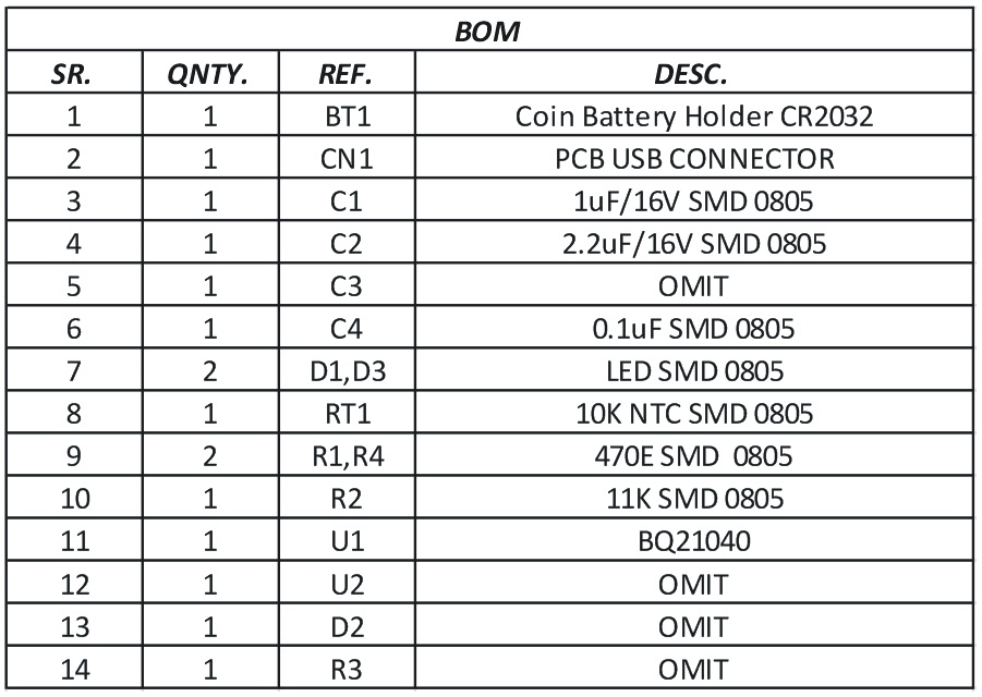
To prevent the list from becoming messy, other components required are provided in the table below. The Oven, External Solid State Relay and Fan are the only parts needed to test after building.
Reference
Value
D1
Red
U3
MAX31856
SW2
IT-1109S
SW1
IT-1109S
SW3
TS-018
R1
2K2
LS1
HYG9605B
R2
100R
R3
100R
C3
100nF
C2
10nF
C1
10nF
J4
2.54mm 2×3
C4
100nF
C5
10uF 16V X5R
R4
10K
R5
10K
Q2
2N3904
Q1
2N3904
R6
2K2
R7
27K
LOGO1
LOGO-ROCKET-SCREAM
R8
53K6
R9
10K
D3
1N4148WS
C6
100nF
C7
100nF
J2
TERMINAL-BLOCK-1×2
J1
TERMINAL-BLOCK-1×2
C8
100nF
C9
100nF
R10
10K
C11
100nF
C10
10uF 16V X5R
LOGO3
LOGO-ROCKET-SCREAM
LOGO4
LOGO-OSHW
LOGO2
LOGO-KICAD
J3
MICRO-USB
L1
BLM18KG221SN1D
C12
10uF 16V X5R
F1
FUSE
R11
2K2
U4
CH340E
C14
100nF
C13
100nF
U1
ATMEGA328P-MU
C17
100nF
C18
100nF
L2
LBMF1608T100K
Y1
NX3225GD
C15
10pF
C16
10pF
U5
OLED-SSD1306-128X64-I2C
C19
100nF
Q3
2N3904
R12
53K6
J5
TERMINAL-BLOCK-1×2
U2
MCP1700T-3302E-TT
Schematics
As mentioned during the introduction, the Tiny Reflow Controller v2 used SMD parts, which automatically means we need a PCB for our build. The major reason for this is to make the project neat, portable and cheap. However, you can also decide to get the through-hole version of this components and use them to implement the project on a breadboard.
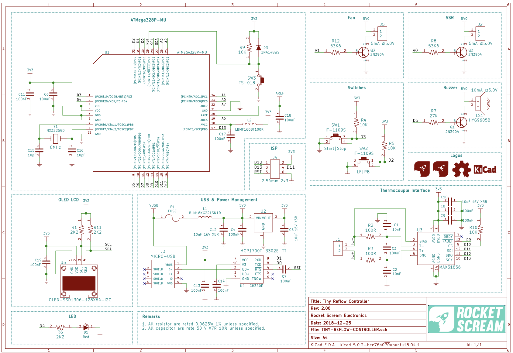
To make it easy to implement the schematics and transition to PCB, the schematics for this project was developed using Kicad. The components are connected as shown in the schematics below;
Schematics
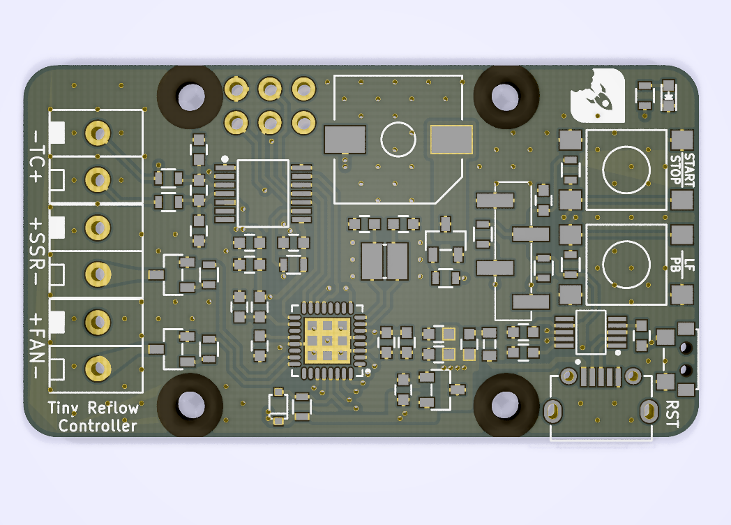
The final PCB design will look like the render below.
Tiny Reflow Controller v2 PCB design
To make the board easy to replicate, all the design files including schematics and PCB are attached under the download section. Feel free to use within the license specifications.
Tiny Reflow Controller v2 assembled
Code
The code for this project will be developed using the Arduino ID and is based on the example code that is shipped with the Tiny Reflow Oven V2 by Rocket Stream. The sketch utilizes a PID based control algorithm of the awesome Arduino PID Library developed by Brett Beauregard and it is used to manage the reflow process, using the heater and the fan to ensure the heat is adequate for every stage of the reflow process.
The sketch utilizes three major libraries including; the Arduino PID Library already mentioned, Adafruit MAX31856 Library, Adafruit SSD1306 Library, and the Adafruit GFX Library. The PID library as mentioned earlier was used to ensure accuracy in heat levels with heat applied based on the current heat levels. The Adafruit SSD1306 and GFX libraries, on the other hand, were used to facilitate interaction with the OLED, and the Adafruit Max318356 library was used to reduce the amount of work involved in obtaining readings from the thermocouple sensor.
As usual, I will do a brief explanation of the code highlighting the major parts. The example code we will work with, takes into account both leaded and lead-free reflow oven configurations, allowing users to change from one to the other via a single push button.
We start the sketch by including all the libraries that we will use. In addition to the libraries already mentioned above, we will also use the Arduino EEPROM library, the Wire library and the SPI library. All these libraries come with the Arduino IDE so there is no need to manually install them.
// ***** INCLUDES *****
#include <SPI.h>
#include <Wire.h>
#include <EEPROM.h>
#include <LiquidCrystal.h>
#include <Adafruit_GFX.h>      // Comment for VERSION 1
#include <Adafruit_SSD1306.h>  // Comment for VERSION 1
#include <Adafruit_MAX31856.h>
#include <PID_v1.h>
Next, we create a type definition that holds several parameters to indicate the state of the reflow process.
Next, we create variables to hold constant values that will be used irrespective of the profile selected (General Profile constants) and we follow it up by creating variables to hold values specific to Lead-free profile and also create those specific to the Leaded profile. This ensures that irrespective of the profile selected by the user, the necessary information will be available.
Next, we create variables to be used by the PID Algorithm, specify the project version so the right display is used, and create messages to be displayed on the OLED along with a few other variables. The names are very descriptive so it should be easy to follow.
The sketch was designed to be compatible with the v1 of the project, with the version decision being made by the version indicated by the user in the code. As a result, you may continue to see things that relate to the first version of the project. Next, we declare the pins to which the displays are connected, with the OLED declarations under v2.
Several other important variables are also declared with self descriptive names.
// ***** PID CONTROL VARIABLES *****
double setpoint;
double input;
double output;
double kp = PID_KP_PREHEAT;
double ki = PID_KI_PREHEAT;
double kd = PID_KD_PREHEAT;
int windowSize;
unsigned long windowStartTime;
unsigned long nextCheck;
unsigned long nextRead;
unsigned long updateLcd;
unsigned long timerSoak;
unsigned long buzzerPeriod;
unsigned char soakTemperatureMax;
unsigned char reflowTemperatureMax;
unsigned long soakMicroPeriod;
// Reflow oven controller state machine state variable
reflowState_t reflowState;
// Reflow oven controller status
reflowStatus_t reflowStatus;
// Reflow profile type
reflowProfile_t reflowProfile;
// Switch debounce state machine state variable
debounceState_t debounceState;
// Switch debounce timer
long lastDebounceTime;
// Switch press status
switch_t switchStatus;
switch_t switchValue;
switch_t switchMask;
// Seconds timer
unsigned int timerSeconds;
// Thermocouple fault status
unsigned char fault;
With all the variables created, we then create an instance of the PID, the SSD1306 and the MAX31856 libraries after which we move to the void setup() function.
We start the void setup() function by checking the currently selected reflow profile on the EEPROM and this helps determine which of the variable groups should be selected. If no reflow profile was previously stored, the system selects the Lead-free profile by default.
void setup()
{
  // Check current selected reflow profile
  unsigned char value = EEPROM.read(PROFILE_TYPE_ADDRESS);
  if ((value == 0) || (value == 1))
  {
    // Valid reflow profile value
    reflowProfile = value;
  }
  else
  {
    // Default to lead-free profile
    EEPROM.write(PROFILE_TYPE_ADDRESS, 0);
    reflowProfile = REFLOW_PROFILE_LEADFREE;
  }
Next, we initialize the SSR pin to ensure the reflow oven is open after which we initialize the buzzer setting it to turn on immediately when the system powers up, the status LED is also powered on when the systems starts.
// SSR pin initialization to ensure reflow oven is off
digitalWrite(ssrPin, LOW);
pinMode(ssrPin, OUTPUT);

// Buzzer pin initialization to ensure annoying buzzer is off
digitalWrite(buzzerPin, LOW);
pinMode(buzzerPin, OUTPUT);

// LED pins initialization and turn on upon start-up (active high)
pinMode(ledPin, OUTPUT);
digitalWrite(ledPin, HIGH);
Next, we initialize the thermocouple, indicating the type, and also initialize the OLED and display a sort of splash screen with the date and version of the controller. The code selectively runs every thing marked for 2.
Next, we initialize serial communication, turn off the Status LED, and initialize the variables we will use to monitor time as the sketch runs.
// Serial communication at 115200 bps
  Serial.begin(115200);

  // Turn off LED (active high)
  digitalWrite(ledPin, LOW);
  // Set window size
  windowSize = 2000;
  // Initialize time keeping variable
  nextCheck = millis();
  // Initialize thermocouple reading variable
  nextRead = millis();
  // Initialize LCD update timer
  updateLcd = millis();
}
With this done, we move to the void loop() function where all the major actions take place.
The code for the void loop() function is quite bulky but the idea is simple. We use the variables created earlier to manage the reflow process, monitoring the amount of heat with the thermocouple, and using that information as an input into the PID algorithm which then determines how the heater operates. For each stage in the reflow process, the PID operates in such a way that the designated amount of heat for that stage is achieved. While all of this is going on, the time and temperature information are also being displayed on the screen to provide visual feedback to the user and the switches which are used to set the reflow status and the reflow profile are also being watched so the system can act immediately on any change in their state.
void loop()
{
  // Current time
  unsigned long now;

  // Time to read thermocouple?
  if (millis() > nextRead)
  {
    // Read thermocouple next sampling period
    nextRead += SENSOR_SAMPLING_TIME;
    // Read current temperature
    input = thermocouple.readThermocoupleTemperature();
    // Check for thermocouple fault
    fault = thermocouple.readFault();

    // If any thermocouple fault is detected
    if ((fault & MAX31856_FAULT_CJRANGE) ||
        (fault & MAX31856_FAULT_TCRANGE) ||
        (fault & MAX31856_FAULT_CJHIGH) ||
        (fault & MAX31856_FAULT_CJLOW) ||
        (fault & MAX31856_FAULT_TCHIGH) ||
        (fault & MAX31856_FAULT_TCLOW) ||
        (fault & MAX31856_FAULT_OVUV) ||
        (fault & MAX31856_FAULT_OPEN))
    {
      // Illegal operation
      reflowState = REFLOW_STATE_ERROR;
      reflowStatus = REFLOW_STATUS_OFF;
      Serial.println(F("Error"));
    }
  }

  if (millis() > nextCheck)
  {
    // Check input in the next seconds
    nextCheck += SENSOR_SAMPLING_TIME;
    // If reflow process is on going
    if (reflowStatus == REFLOW_STATUS_ON)
    {
      // Toggle red LED as system heart beat
      digitalWrite(ledPin, !(digitalRead(ledPin)));
      // Increase seconds timer for reflow curve plot
      timerSeconds++;
      // Send temperature and time stamp to serial
      Serial.print(timerSeconds);
      Serial.print(F(","));
      Serial.print(setpoint);
      Serial.print(F(","));
      Serial.print(input);
      Serial.print(F(","));
      Serial.println(output);
    }
    else
    {
      // Turn off red LED
      digitalWrite(ledPin, LOW);
    }
  }

  if (millis() > updateLcd)
  {
    // Update LCD in the next 100 ms
    updateLcd += UPDATE_RATE;
#if VERSION == 1
    // Clear LCD
    lcd.clear();
    // Print current system state
    lcd.print(lcdMessagesReflowStatus[reflowState]);
    lcd.setCursor(6, 0);
    if (reflowProfile == REFLOW_PROFILE_LEADFREE)
    {
      lcd.print(F("LF"));
    }
    else
    {
      lcd.print(F("PB"));
    }
    lcd.setCursor(0, 1);

    // If currently in error state
    if (reflowState == REFLOW_STATE_ERROR)
    {
      // Thermocouple error (open, shorted)
      lcd.print(F("TC Error"));
    }
    else
    {
      // Display current temperature
      lcd.print(input);
#if ARDUINO >= 100
      // Display degree Celsius symbol
      lcd.write((uint8_t)0);
#else
      // Display degree Celsius symbol
      lcd.print(0, BYTE);
#endif
      lcd.print("C ");
    }
#elif VERSION == 2
    oled.clearDisplay();
    oled.setTextSize(2);
    oled.setCursor(0, 0);
    oled.print(lcdMessagesReflowStatus[reflowState]);
    oled.setTextSize(1);
    oled.setCursor(115, 0);

    if (reflowProfile == REFLOW_PROFILE_LEADFREE)
    {
      oled.print(F("LF"));
    }
    else
    {
      oled.print(F("PB"));
    }

    // Temperature markers
    oled.setCursor(0, 18);
    oled.print(F("250"));
    oled.setCursor(0, 36);
    oled.print(F("150"));
    oled.setCursor(0, 54);
    oled.print(F("50"));
    // Draw temperature and time axis
    oled.drawLine(18, 18, 18, 63, WHITE);
    oled.drawLine(18, 63, 127, 63, WHITE);
    oled.setCursor(115, 0);

    // If currently in error state
    if (reflowState == REFLOW_STATE_ERROR)
    {
      oled.setCursor(80, 9);
      oled.print(F("TC Error"));
    }
    else
    {
      // Right align temperature reading
      if (input < 10) oled.setCursor(91, 9);
      else if (input < 100) oled.setCursor(85,9);
      else oled.setCursor(80, 9);
      // Display current temperature
      oled.print(input);
      oled.print((char)247);
      oled.print(F("C"));
    }

    if (reflowStatus == REFLOW_STATUS_ON)
    {
      // We are updating the display faster than sensor reading
      if (timerSeconds > timerUpdate)
      {
        // Store temperature reading every 3 s
        if ((timerSeconds % 3) == 0)
        {
          timerUpdate = timerSeconds;
          unsigned char averageReading = map(input, 0, 250, 63, 19);
          if (x < (SCREEN_WIDTH - X_AXIS_START))
          {
            temperature[x++] = averageReading;
          }
        }
      }
    }

    unsigned char timeAxis;
    for (timeAxis = 0; timeAxis < x; timeAxis++)
    {
      oled.drawPixel(timeAxis + X_AXIS_START, temperature[timeAxis], WHITE);
    }

    // Update screen
    oled.display();
#endif
  }

  // Reflow oven controller state machine
  switch (reflowState)
  {
    case REFLOW_STATE_IDLE:
      // If oven temperature is still above room temperature
      if (input >= TEMPERATURE_ROOM)
      {
        reflowState = REFLOW_STATE_TOO_HOT;
      }
      else
      {
        // If switch is pressed to start reflow process
        if (switchStatus == SWITCH_1)
        {
          // Send header for CSV file
          Serial.println(F("Time,Setpoint,Input,Output"));
          // Intialize seconds timer for serial debug information
          timerSeconds = 0;

          #if VERSION == 2
          // Initialize reflow plot update timer
          timerUpdate = 0;

          for (x = 0; x < (SCREEN_WIDTH - X_AXIS_START); x++)
          {
            temperature[x] = 0;
          }
          // Initialize index for average temperature array used for reflow plot
          x = 0;
          #endif

          // Initialize PID control window starting time
          windowStartTime = millis();
          // Ramp up to minimum soaking temperature
          setpoint = TEMPERATURE_SOAK_MIN;
          // Load profile specific constant
          if (reflowProfile == REFLOW_PROFILE_LEADFREE)
          {
            soakTemperatureMax = TEMPERATURE_SOAK_MAX_LF;
            reflowTemperatureMax = TEMPERATURE_REFLOW_MAX_LF;
            soakMicroPeriod = SOAK_MICRO_PERIOD_LF;
          }
          else
          {
            soakTemperatureMax = TEMPERATURE_SOAK_MAX_PB;
            reflowTemperatureMax = TEMPERATURE_REFLOW_MAX_PB;
            soakMicroPeriod = SOAK_MICRO_PERIOD_PB;
          }
          // Tell the PID to range between 0 and the full window size
          reflowOvenPID.SetOutputLimits(0, windowSize);
          reflowOvenPID.SetSampleTime(PID_SAMPLE_TIME);
          // Turn the PID on
          reflowOvenPID.SetMode(AUTOMATIC);
          // Proceed to preheat stage
          reflowState = REFLOW_STATE_PREHEAT;
        }
      }
      break;

    case REFLOW_STATE_PREHEAT:
      reflowStatus = REFLOW_STATUS_ON;
      // If minimum soak temperature is achieve
      if (input >= TEMPERATURE_SOAK_MIN)
      {
        // Chop soaking period into smaller sub-period
        timerSoak = millis() + soakMicroPeriod;
        // Set less agressive PID parameters for soaking ramp
        reflowOvenPID.SetTunings(PID_KP_SOAK, PID_KI_SOAK, PID_KD_SOAK);
        // Ramp up to first section of soaking temperature
        setpoint = TEMPERATURE_SOAK_MIN + SOAK_TEMPERATURE_STEP;
        // Proceed to soaking state
        reflowState = REFLOW_STATE_SOAK;
      }
      break;

    case REFLOW_STATE_SOAK:
      // If micro soak temperature is achieved
      if (millis() > timerSoak)
      {
        timerSoak = millis() + soakMicroPeriod;
        // Increment micro setpoint
        setpoint += SOAK_TEMPERATURE_STEP;
        if (setpoint > soakTemperatureMax)
        {
          // Set agressive PID parameters for reflow ramp
          reflowOvenPID.SetTunings(PID_KP_REFLOW, PID_KI_REFLOW, PID_KD_REFLOW);
          // Ramp up to first section of soaking temperature
          setpoint = reflowTemperatureMax;
          // Proceed to reflowing state
          reflowState = REFLOW_STATE_REFLOW;
        }
      }
      break;

    case REFLOW_STATE_REFLOW:
      // We need to avoid hovering at peak temperature for too long
      // Crude method that works like a charm and safe for the components
      if (input >= (reflowTemperatureMax - 5))
      {
        // Set PID parameters for cooling ramp
        reflowOvenPID.SetTunings(PID_KP_REFLOW, PID_KI_REFLOW, PID_KD_REFLOW);
        // Ramp down to minimum cooling temperature
        setpoint = TEMPERATURE_COOL_MIN;
        // Proceed to cooling state
        reflowState = REFLOW_STATE_COOL;
      }
      break;

    case REFLOW_STATE_COOL:
      // If minimum cool temperature is achieve
      if (input <= TEMPERATURE_COOL_MIN)
      {
        // Retrieve current time for buzzer usage
        buzzerPeriod = millis() + 1000;
        // Turn on buzzer to indicate completion
        digitalWrite(buzzerPin, HIGH);
        // Turn off reflow process
        reflowStatus = REFLOW_STATUS_OFF;
        // Proceed to reflow Completion state
        reflowState = REFLOW_STATE_COMPLETE;
      }
      break;

    case REFLOW_STATE_COMPLETE:
      if (millis() > buzzerPeriod)
      {
        // Turn off buzzer
        digitalWrite(buzzerPin, LOW);
        // Reflow process ended
        reflowState = REFLOW_STATE_IDLE;
      }
      break;

    case REFLOW_STATE_TOO_HOT:
      // If oven temperature drops below room temperature
      if (input < TEMPERATURE_ROOM)
      {
        // Ready to reflow
        reflowState = REFLOW_STATE_IDLE;
      }
      break;

    case REFLOW_STATE_ERROR:
      // Check for thermocouple fault
      fault = thermocouple.readFault();

      // If thermocouple problem is still present
      if ((fault & MAX31856_FAULT_CJRANGE) ||
          (fault & MAX31856_FAULT_TCRANGE) ||
          (fault & MAX31856_FAULT_CJHIGH) ||
          (fault & MAX31856_FAULT_CJLOW) ||
          (fault & MAX31856_FAULT_TCHIGH) ||
          (fault & MAX31856_FAULT_TCLOW) ||
          (fault & MAX31856_FAULT_OVUV) ||
          (fault & MAX31856_FAULT_OPEN))
      {
        // Wait until thermocouple wire is connected
        reflowState = REFLOW_STATE_ERROR;
      }
      else
      {
        // Clear to perform reflow process
        reflowState = REFLOW_STATE_IDLE;
      }
      break;
  }

  // If switch 1 is pressed
  if (switchStatus == SWITCH_1)
  {
    // If currently reflow process is on going
    if (reflowStatus == REFLOW_STATUS_ON)
    {
      // Button press is for cancelling
      // Turn off reflow process
      reflowStatus = REFLOW_STATUS_OFF;
      // Reinitialize state machine
      reflowState = REFLOW_STATE_IDLE;
    }
  }
  // Switch 2 is pressed
  else if (switchStatus == SWITCH_2)
  {
    // Only can switch reflow profile during idle
    if (reflowState == REFLOW_STATE_IDLE)
    {
      // Currently using lead-free reflow profile
      if (reflowProfile == REFLOW_PROFILE_LEADFREE)
      {
        // Switch to leaded reflow profile
        reflowProfile = REFLOW_PROFILE_LEADED;
        EEPROM.write(PROFILE_TYPE_ADDRESS, 1);
      }
      // Currently using leaded reflow profile
      else
      {
        // Switch to lead-free profile
        reflowProfile = REFLOW_PROFILE_LEADFREE;
        EEPROM.write(PROFILE_TYPE_ADDRESS, 0);
      }
    }
  }
  // Switch status has been read
  switchStatus = SWITCH_NONE;

  // Simple switch debounce state machine (analog switch)
  switch (debounceState)
  {
    case DEBOUNCE_STATE_IDLE:
      // No valid switch press
      switchStatus = SWITCH_NONE;

      switchValue = readSwitch();

      // If either switch is pressed
      if (switchValue != SWITCH_NONE)
      {
        // Keep track of the pressed switch
        switchMask = switchValue;
        // Intialize debounce counter
        lastDebounceTime = millis();
        // Proceed to check validity of button press
        debounceState = DEBOUNCE_STATE_CHECK;
      }
      break;

    case DEBOUNCE_STATE_CHECK:
      switchValue = readSwitch();
      if (switchValue == switchMask)
      {
        // If minimum debounce period is completed
        if ((millis() - lastDebounceTime) > DEBOUNCE_PERIOD_MIN)
        {
          // Valid switch press
          switchStatus = switchMask;
          // Proceed to wait for button release
          debounceState = DEBOUNCE_STATE_RELEASE;
        }
      }
      // False trigger
      else
      {
        // Reinitialize button debounce state machine
        debounceState = DEBOUNCE_STATE_IDLE;
      }
      break;

    case DEBOUNCE_STATE_RELEASE:
      switchValue = readSwitch();
      if (switchValue == SWITCH_NONE)
      {
        // Reinitialize button debounce state machine
        debounceState = DEBOUNCE_STATE_IDLE;
      }
      break;
  }

  // PID computation and SSR control
  if (reflowStatus == REFLOW_STATUS_ON)
  {
    now = millis();

    reflowOvenPID.Compute();

    if ((now - windowStartTime) > windowSize)
    {
      // Time to shift the Relay Window
      windowStartTime += windowSize;
    }
    if (output > (now - windowStartTime)) digitalWrite(ssrPin, HIGH);
    else digitalWrite(ssrPin, LOW);
  }
  // Reflow oven process is off, ensure oven is off
  else
  {
    digitalWrite(ssrPin, LOW);
  }
}
The complete Sketch for the project is quite bulky so it is attached to the zip file under the download section, at the end of the page.
Demo
One great thing about the Tiny Reflow Controller v2 is the fact that it comes with a USB port through which it can be programmed. However, you may still need to do some work on your Arduino IDE (like Flashing the bootloader to the Atmeg328p in case it doesn’t come with one) to ensure you can upload code to it. You can check out this tutorial we wrote a while back on the programming the Atmega328p with the Arduino IDE.
This board uses the stock Arduino Pro Mini ATmega328 3.3V 8MHz bootloader and it can be loaded just like V1 using the AVRISP mkII.
Connect the completed Reflow Controller v2 to your computer. Copy the code above, Paste in the IDE, Verify and hit the upload button. After uploading, you should see the splashscreen come up as shown in the image below, connect your SSR, fan and thermocouple. The Reflow controller is ready for use.
Installation
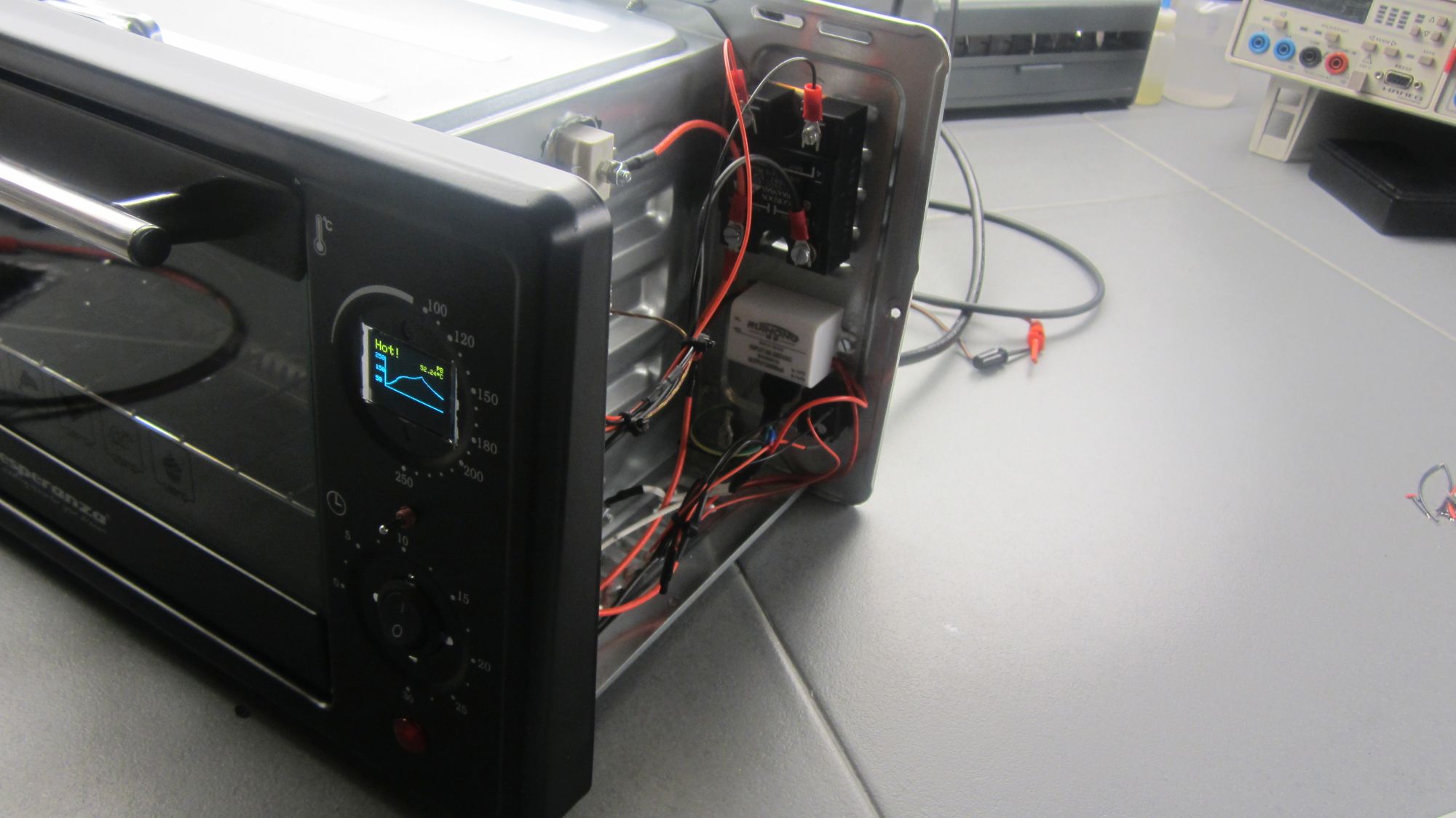
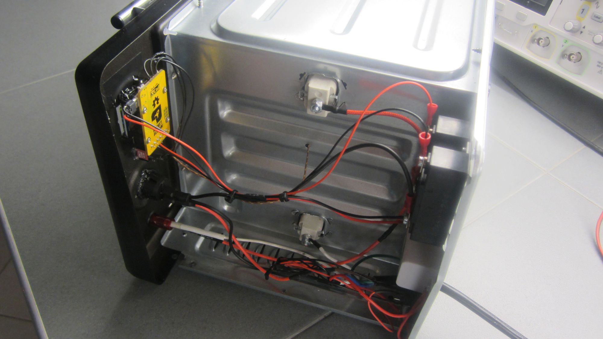
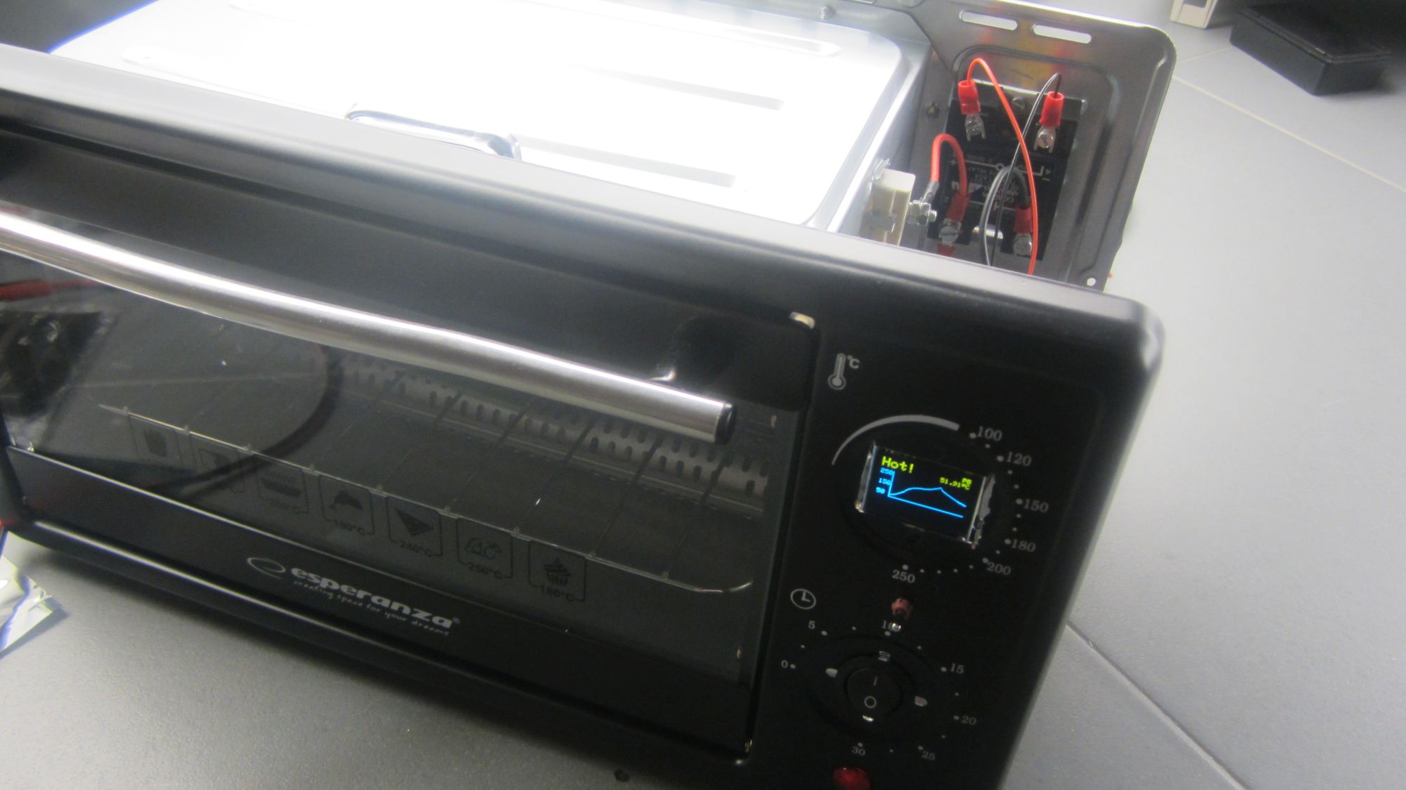
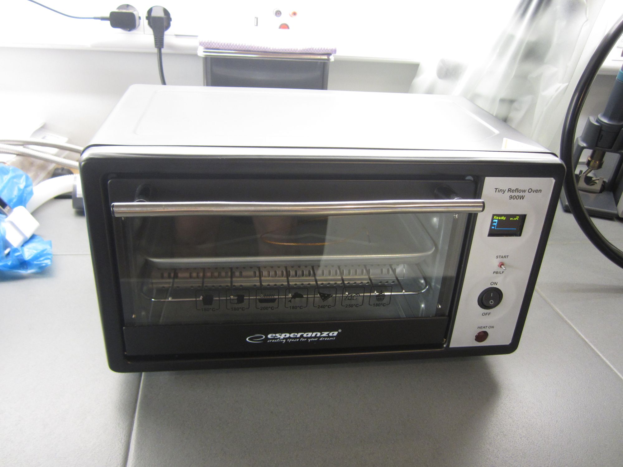
We installed the Tiny Reflow Controller v2 on a small oven rated at 900W and we tested its performance. As you can see in the photos below the reflow controller is installed on the front face, with the solid-state relay and the mini 5V power supply on the back. We were going to also install a cooling fan, but according to advice from the project author, natural cooling works better and stresses the components at a minimum. Also, the FAN output of the board isn’t implemented on the firmware so it would need some additional code to make it work. So, we decided not to install a fan at this moment.
Tiny Reflow v2 installed on the front face of 900W ovenSolid-state relay and a small 5V power supply was installed on the back o the ovenan angle view of the oven just completed a reflow cycle.
Reflow Results
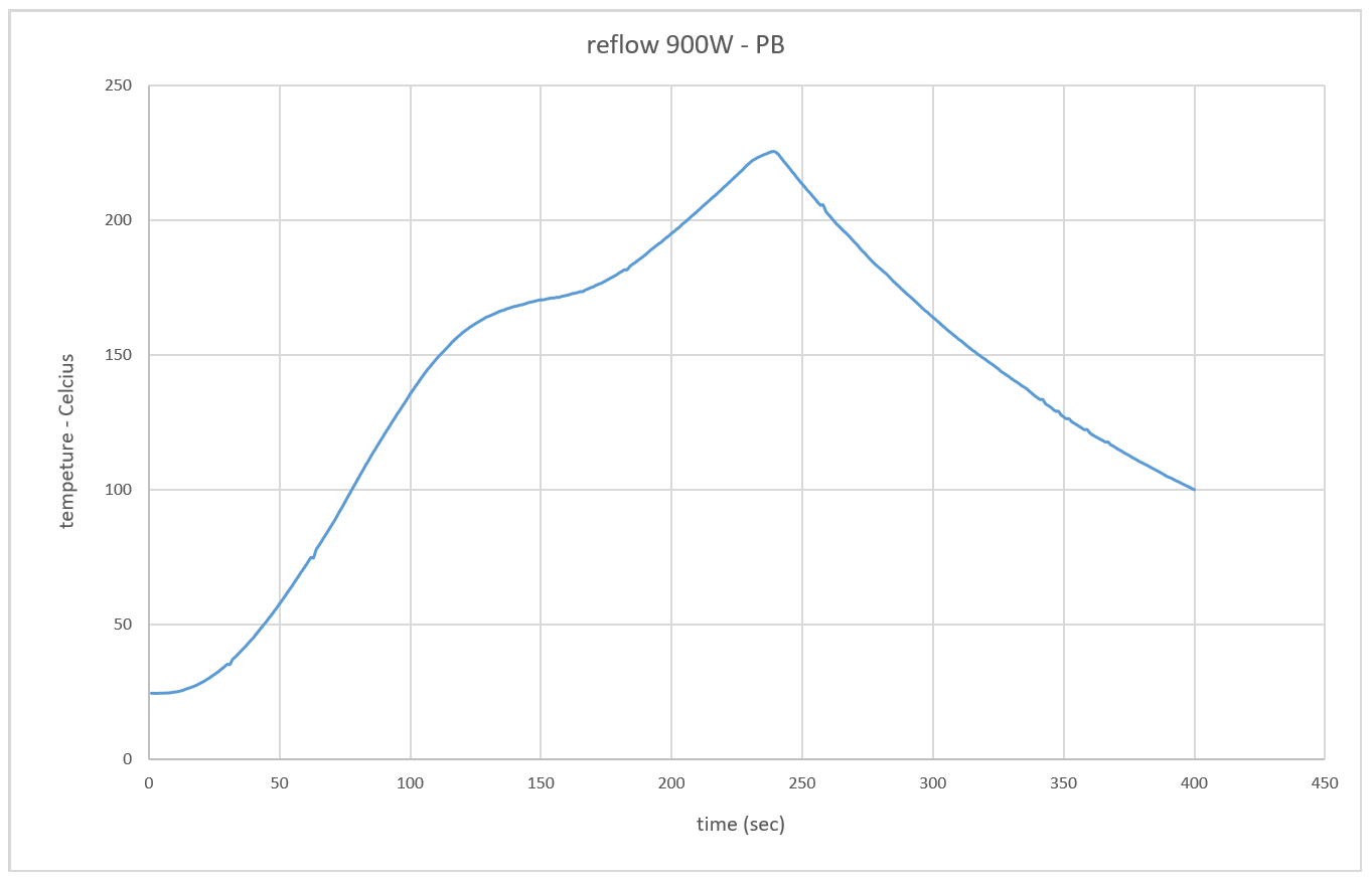
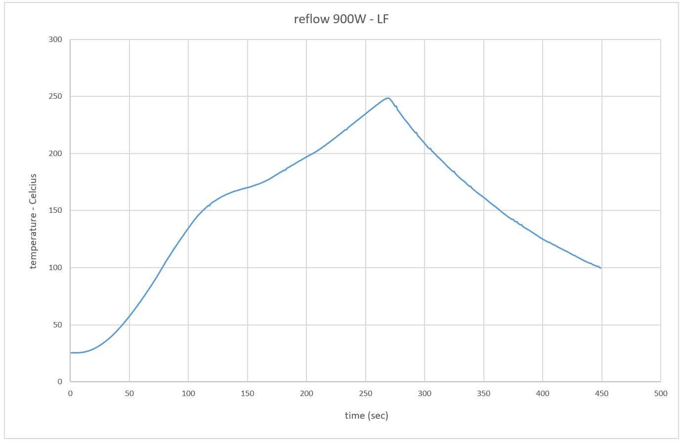
As we said before the board supports two reflow profiles, a PB and a Lead-free (LF), both selected before the reflow cycle starts. The controller has an onboard serial to USB converter, so to capture the data during the reflow, all you need is to connect a USB cable, launch your favorite RS232 terminal, set the serial config tot 115200 bps 8N1 and you are ready to go. Upon pressing the start button, temperature data is logged on the terminal along with time, setpoint and heating elements ON time. We tested both profiles by doing a full reflow cycle for each one and we share the results here. During our initial tests, we experience some issues, like we couldn’t successfully complete a reflow cycle, followed by an Error on screen. This could mean that the thermocouple touched a conductive part of the PCB, that shortcircuit it, or the TC was disconnected from the board or that there was more noise on the power rail that the board could tolerate. It proved that our case was the noise issue and that after replacing the USB cable with one that had a ferrite bead in line, the reflow cycle was completed successfully.
reflow cycle for PB profilereflow cycle for LF profile
As you can see from the graphs above, both profiles start from room temperature (25ºC) and reach the soak phase after around 115 sec. Then the reflow stage starts and reaches 220ºC for PB and 245ºC for LF. We see that both profiles are smooth and clean and that could guarantee that your reflow soldering could be successful.
Video
Conclusion
Finished Reflow Oven v2
The major difference between the TinyReflow Controller v2 and the v1 is the use of the OLED display which displays a Graph of the reflow process and the built-in USB-Serial interface which takes away the need for a converter when programming the board.
Looking for a good reflow oven that works well with this controller? You can go through this list curated by Rocket Stream to get suggestions on the best kind of ovens to use with the tiny reflow controller or visit their eshop to purchase an already assembled and tested board.
That’s it for today’s tutorial. Thanks for reading. As usual, feel free to reach out to me via the comment section if you have any question about the project and also let me know if you made one using this guide.
Low quiescent current, also called supply current, might be an important spec for your power-supply design.. by Paul Rako @ electronicdesign.com
Quiescent current is the current that a chip needs to operate even if it’s not delivering power. It’s the bare minimum supply current the chip will use. For buck-regulator chips, improved processes have reduced quiescent currents over the years. The tighter process controls of modern chip manufacturing also mean that the range of Iq from chip to chip will vary less than in the old days.
Iq is why any buck-regulator chip will have worsening efficiency as your circuitry requires less power. Since the Iq is the constant “floor” of power needed to run the chip, it will be a smaller percentage of efficiency loss when the chip is delivering full power than when the chip is just idling, and your circuits that it’s powering are taking their minimum power.
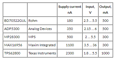
Here are five buck-regulator chips with low quiescent current. Note that a buck-regulator chip is generally thought of as having the power switching transistors inside the part itself. A buck regulator controller uses external power transistors to do the high-current switching.
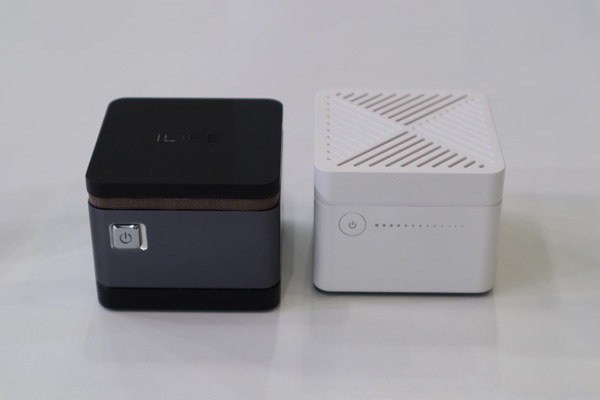
iLife MP8 micro PC looks to be the smallest Win10 mini PC, powered by an Intel Celeron N4100 quad-core Gemini Lake processor with 4GB RAM and 64GB storage.
The Windows 10 micro PC was showcased at the Hong Kong Electronics Fair, where the company also displayed its iLife NY08 mini laptop sold as CHUWI Minibook. Notebook Italia was at the event and shot a video showing both devices.
The company representative did not provide exact measurements and instead showed that iLife MP8 micro PC used about a quarter of the area taken up by a standard mini PC. But based on the photos and knowing an HDMI female connector has a width of 14mm, we can estimate the dimensions to be around 50 x 50 x 40 mm. That’s even smaller than the Arm-based Solidrun Cubox Pulse mini PC (50 x 50 x 50 mm).
iLife MP8 micro PC is actively cooled and comes in two versions with either a black metal enclosure with vents on the sides or a white plastic enclosure with ventilation holes on the top. If you wonder about Linux support, we’ve found that Gemini Lake mini PCs usually support Linux well, but not always.
Pricing and availability are unknown at this stage, and it’s possible, or even likely, the mini PC will eventually be sold under another name.
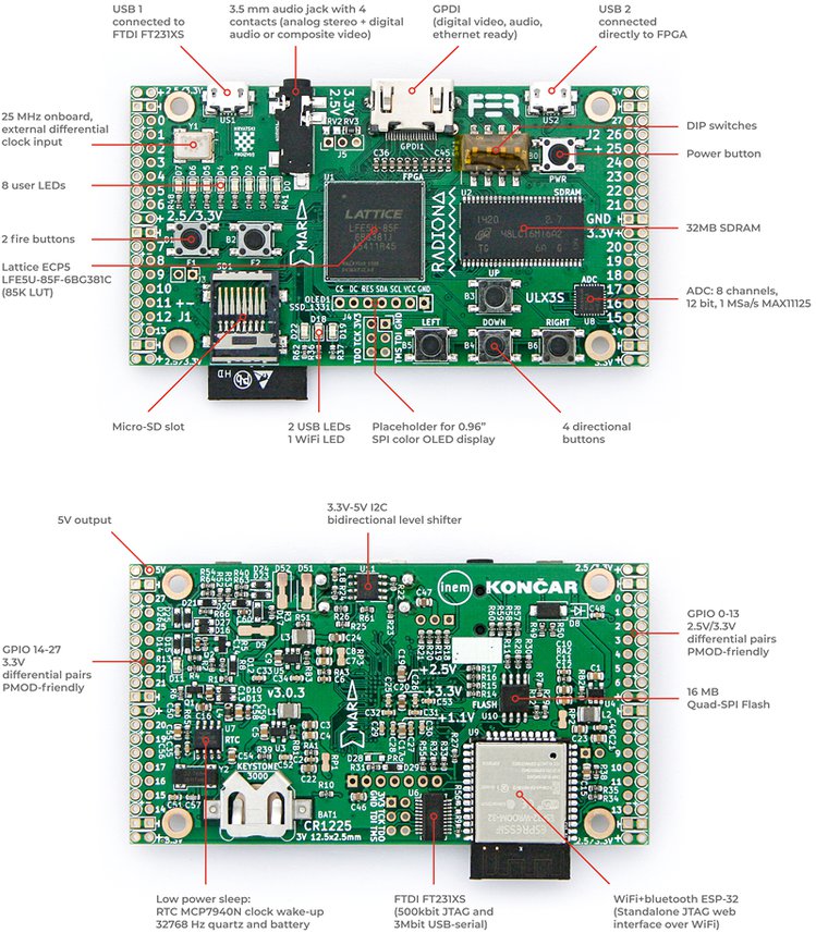
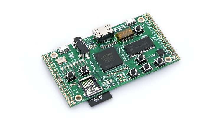
ULX3S is a fully open source, compact, robust, and affordable FPGA dev board equipped with a balanced selection of additional components and expansions. Although it was designed primarily as a teaching tool for mastering the principles of digital circuit design, ULX3S incorporates a wide array of features and interfaces that allow it to serve as a broadly useful module for installation in complex devices.
Built around a powerful Lattice Semiconductor ECP5-series FPGA chip and supported by the latest open-source toolchains, ULX3S is one of the most powerful and desirable platforms available for FPGA enthusiasts. It comes equipped with onboard Wi-Fi, display, buttons, LEDs, and storage. Flash it with an over-the-air (OTA) update using the Wi-Fi connection or take advantage of the onboard OLED display and buttons to browse the contents of an SD card and select a bitstream. Due to its battery-backed RTC, ULX3S can power down completely and wake up only in response to certain events. This feature makes it perfect for use in low-power applications such as battery-powered remote sensor nodes.
And if you’re not the low-power type, onboard peripherals like SDRAM, USB, digital video out, onboard FM/ASK antenna, ADC, and DAC make it an audio/video powerhouse for signal processing and synthesis, motor control, and SDR use cases. It can emulate arcade machines and retro computers like the Minimig (Amiga) or modern systems like the F32C (MIPS/RISCV). It has 56 GPIO pins, all routed as differential pairs, and a PMOD compatible pinout, which opens it up to a wide range of expansion options. And if you are just starting out FPGAs, you can use the Arduino IDE to program ULX3S in seconds.
ULX3S has been actively developed since 2016 and is the result of a collaboration between Radiona.org / Zagreb Makerspace and FER – the Faculty of Electrical Engineering and Computing – at the University of Zagreb in Croatia.
Features & Specifications
FPGA: Lattice ECP5 LFE5U-85F-6BG381C (84K LUT)
USB: FTDI FT231XS (500 kbit JTAG and 3 Mbit USB-serial)
GPIO: 56 pins (28 differential pairs), PMOD-friendly with power out 3.3 V at 1 A or 2.5 V at 1.5 A
RAM: 32 MB SDRAM 166 MHz
Flash: 4-16 MB Quad-SPI Flash for FPGA config and user data storage
Mass Storage: Micro-SD slot
LEDs: 11 (8 user LEDs, 2 USB LEDs, 1 Wi-Fi LED)
Buttons: 7 (4 direction, 2 fire, 1 power button)
Audio: 3.5 mm jack with 4 contacts (analog stereo + digital audio or composite video)
Video: Digital video (GPDI General-Purpose Differential Interface) with 3.3 V to 5 V I²C bidirectional level shifter
Display: Placeholder for 0.96” SPI COLOR OLED SSD1331
Wi-Fi & Bluetooth: Placeholder for ESP32 (standalone JTAG web interface over Wi-Fi)
Antenna: 27, 88-108, 144, 433 MHz FM/ASK onboard
ADC: 8 channels, 12 bit, 1 MS a/s MAX11125
Power: 3 Switching voltage regulators: 1.1 V, 2.5 V, and 3.3 V
The simplicity of the Arduino IDE has made it one of the most popular in the world — it’s easy enough for beginners and fast for advanced users. Millions of you have used it as your everyday tool to program projects and applications. We’ve listened to your feedback though, and it’s time for a new enhanced version with features to appeal to the more advanced developers amongst you — while retaining continuity with the simple, classic Arduino IDE that so many of you are familiar with.
We are very excited to announce the release of an alpha version of a completely new development environment for Arduino — the Arduino Pro IDE.
The main features in this initial alpha release of the new Arduino Pro IDE are:
Modern, fully featured development environment
Dual Mode, Classic Mode (identical to the Classic Arduino IDE) and Pro Mode (File System view)
New Board Manager
New Library Manager
Board List
Basic Auto Completion (Arm targets only)
Git Integration
Serial Monitor
Dark Mode
But the new architecture opens the door to features that the Arduino community have been requesting like these that will be following on soon:
Sketch synchronisation with Arduino Create Editor
Debugger
Fully open to third party plug-ins
Support for additional languages other than C++
The new Arduino Pro IDE is based on the latest technologies:
The Arduino CLI running in daemon mode provides all the main Arduino features.
Electron, the framework behind Eclipse Theia, allows the use of web technologies on desktop environments.
Available in Windows,Mac OS X and Linux64 versions; we need your help in improving the product. Before releasing the source code to move out of the alpha, we would greatly appreciate your feedback. Like all things in the Arduino community, we grow and develop together through your valued contributions. Please test the Arduino Pro IDE to it’s breaking point, we want to hear all the good and bad things you find. We’re open to recommendations for additional features, as well as hearing about any bugs you may find — there’s bound to be a few as it is an alpha version after all!
Versions(released on Saturday, October 19th at 16.00 CET)
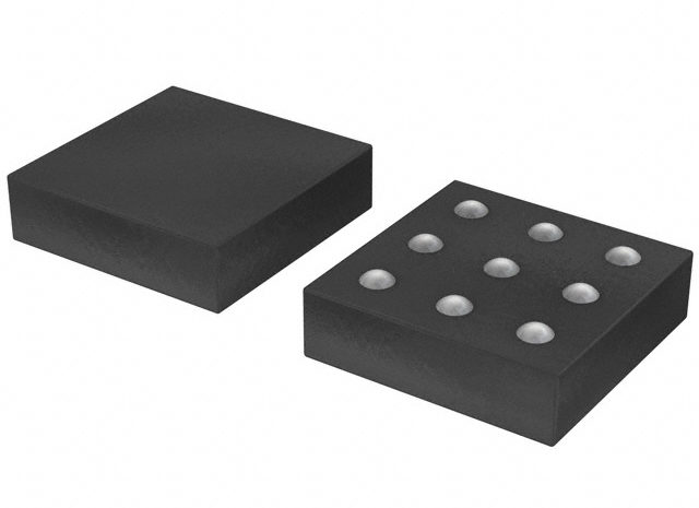
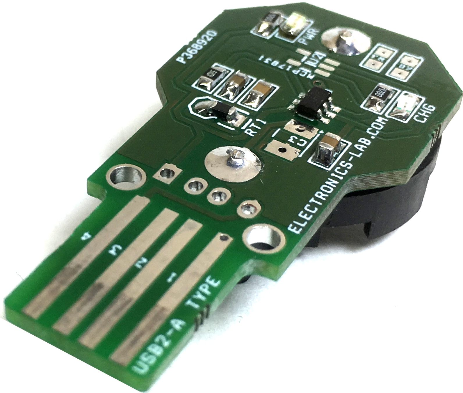
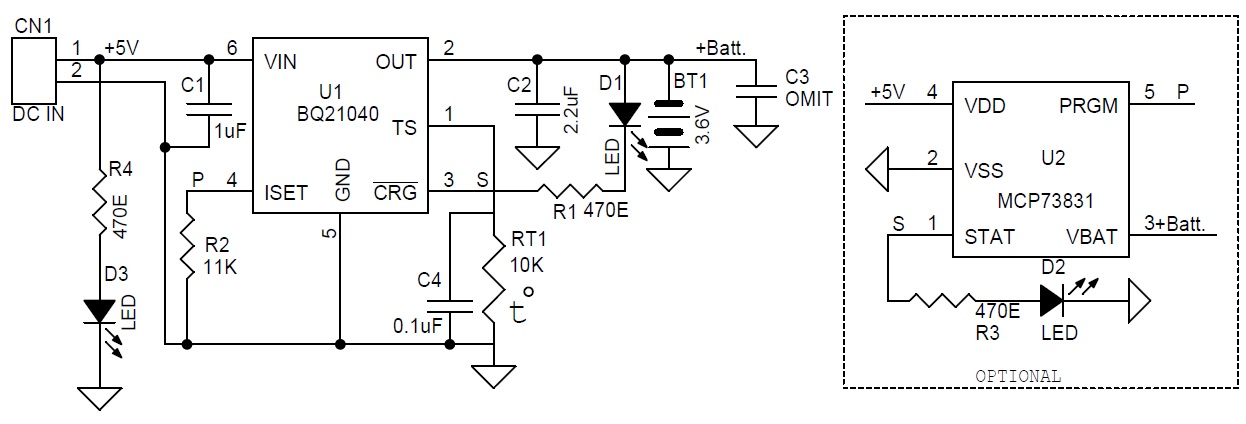
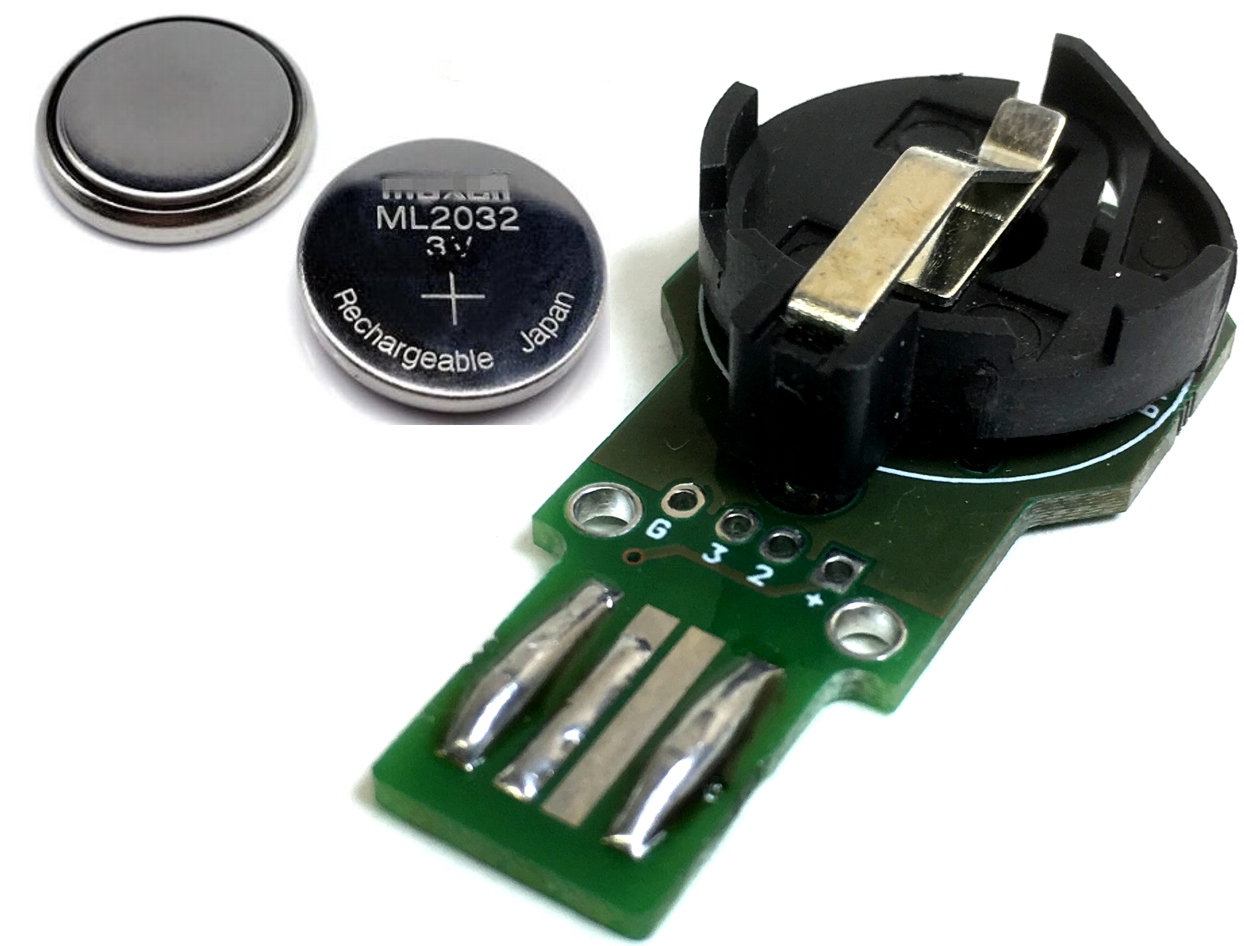
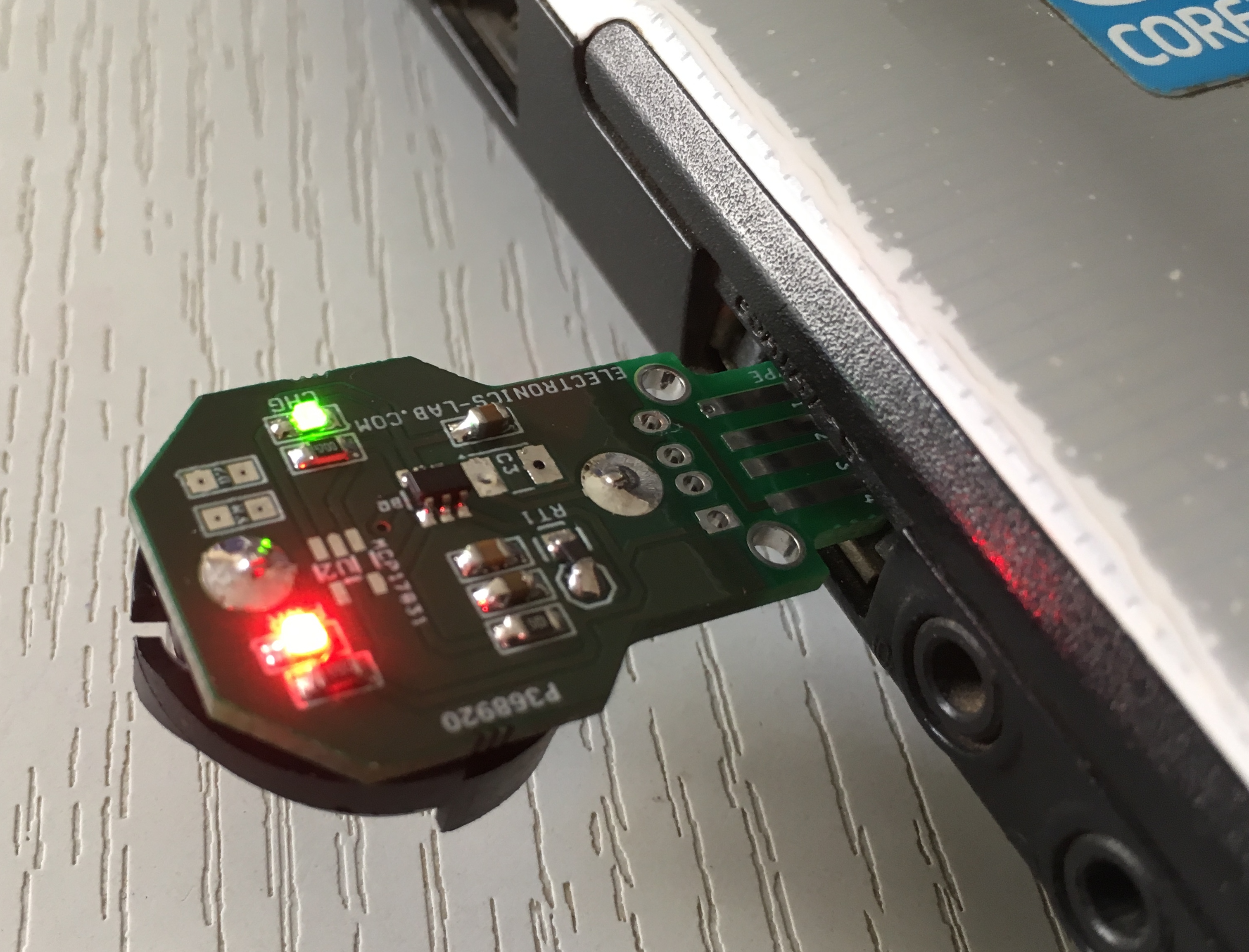
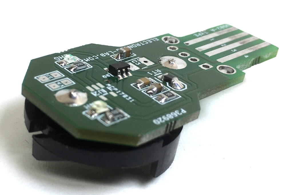
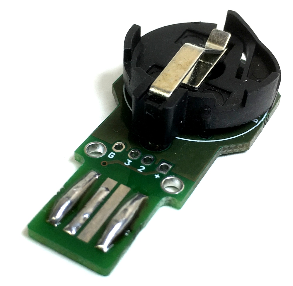
This versatile charger has been designed to charge Lithium Coin Cell Rechargeable CR2016/CR2025/CR2032 Coin Batteries. Just insert the battery to the holder, and plug in to any USB port to recharge, D3 Power LED, D1 LED indicates the charge cycle. The board has been designed to use dual chips, either BQ21040 IC from Texas instruments or MCP73831 from Microchip however the board is tested with BQ21040 IC.
Programmable Charge Current using External Resistor up to 800 mA (default set to 50mA), follow formula bellow to set the desired current.
An external resistor R2 is used to Program the Output Current (50 to 800 mA) and can be used as a current monitor.
This versatile charger has been designed to charge Lithium Coin Cell Rechargeable CR2016/CR2025/CR2032 Coin Batteries. Just insert the battery to the holder, and plug in to any USB port to recharge, D3 Power LED, D1 LED indicates the charge cycle. The board has been designed to use dual chips, either BQ21040 IC from Texas instruments or MCP73831 from Microchip however the board is tested with BQ21040 IC.
Programmable Charge Current using External Resistor up to 800 mA (default set to 50mA), follow the formula bellow to set the desired current.
An external resistor R2 is used to Program the Output Current (50 to 800 mA) and can be used as a current monitor.
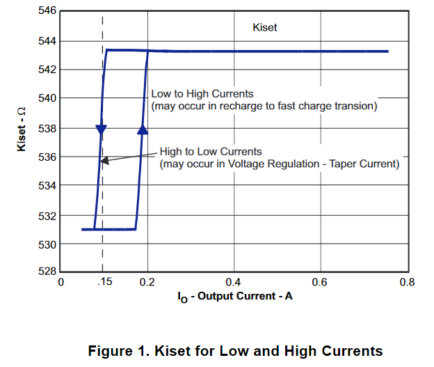
RISET = KISET / IOUT
Where
IOUT is the desired fast charge current;
KISET is a gain factor found in the electrical specification (1)
For greater accuracy at lower currents, part of the sense FET is disabled to give better resolution. Figure 1 shows the transition from low current to higher current. Going from higher currents to low currents, there is hysteresis and the transition occurs around 0.15 A.
For host monitoring, a pull-up resistor is used between the STATUS terminal and the VCC of the host and for a visual indication a resistor in series with an LED is connected between the STATUS terminal and a power source. First charge after Input supply applied LED will be ON and LED will be OFF when OVP/SLEEP condition.
BQ21040 – Single-Input, Single Cell Li-Ion and Li-Pol Battery Charger
The bq21040 device is a highly integrated Li-Ion and Li-Pol linear battery charger device targeted at space limited portable applications. The device operates from either a USB port or AC adapter. The high input voltage range with input overvoltage protection supports low-cost unregulated adapters. The bq21040 has a single power output that charges the battery. A system load can be placed in parallel with the battery as long as the average system load does not keep the battery from charging fully during the 10 hour safety timer. The battery is charged in three phases: conditioning, constant current and constant voltage. In all charge phases, an internal control loop monitors the IC junction temperature and reduces the charge current if an internal temperature threshold is exceeded. The charger power stage and charge current sense functions are fully integrated. The charger function has high accuracy current and voltage regulation loops, charge status display, and charge termination.
The pre-charge current and termination current threshold are fixed to 20% and 10%, respectively. The fast charge current value is programmable through an external resistor.
Note: The board provides dual option for the charging IC, refer to datasheet of MCP73831 and use appropriate components as per data sheet.
Features (BQ21040)
Supply Input 5V USB Port
1% Charge Voltage Accuracy
10% Charge Current Accuracy
Low Battery Leakage Current (1 μA)
Output Current Approx. 50mA
2-V Li-Ion and Li-Pol Coin Battery CR2016/CR2025/CR2032
Over temperature Sensing Protection Through NTC
Fixed 10-Hour Safety Timer
Status Indication – Charging/Done
OUT Short-Circuit Protection and ISET Short Detection
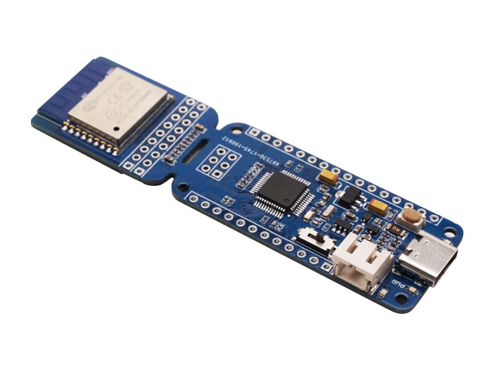
Recently, there was a lot of buzz as the 32bit general purpose GigaDevice GD32V which is based on RISC-V open architecture as well as the Longan Nano development board with LCD display were launched into the board market. Compared to the formerly released GD32 Arm Cortex-M3 microcontroller, the GD32V RISC-V MCU is expected to deliver 15% performance improvement in Coremark and 25 – 50% lower power consumption. However, since many applications require network connectivity, there is still a strong need for wireless SoCs for RISC-V MCUs and while the founding members of the RISC-V foundation are seemingly not doing anything about it, Seeed Studio is taking a bold step and has launched the new Wio Lite RISC – V board with the ESP8266 WiFi module to bring Wi-Fi connectivity to GD32V MCU.
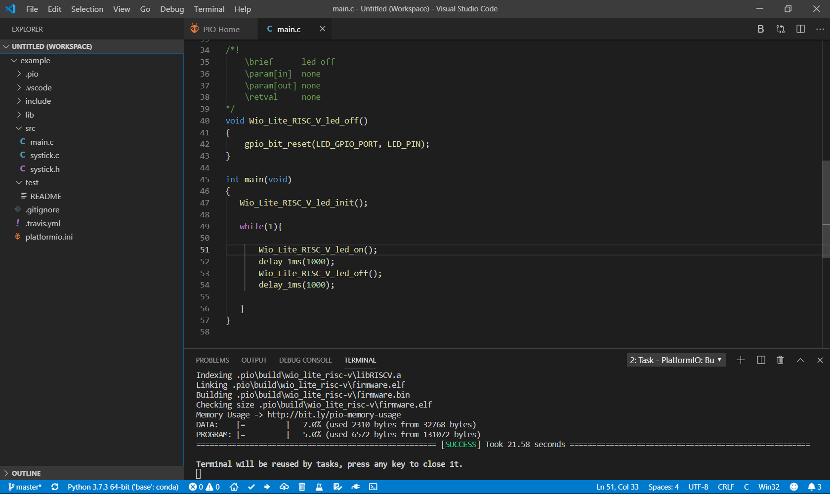
programming enviroment
The Wio Lite has a feather form factor that allows for feathering add-on board compatibility. It also has a similar development environment as the Longan Nano board and a support for LieOS and RT-Thread operating systems, as well as tools like the Arduino IDE, OpenOCD, PlatformIO IDE and GCC. Some of Wio Lite specifications include:
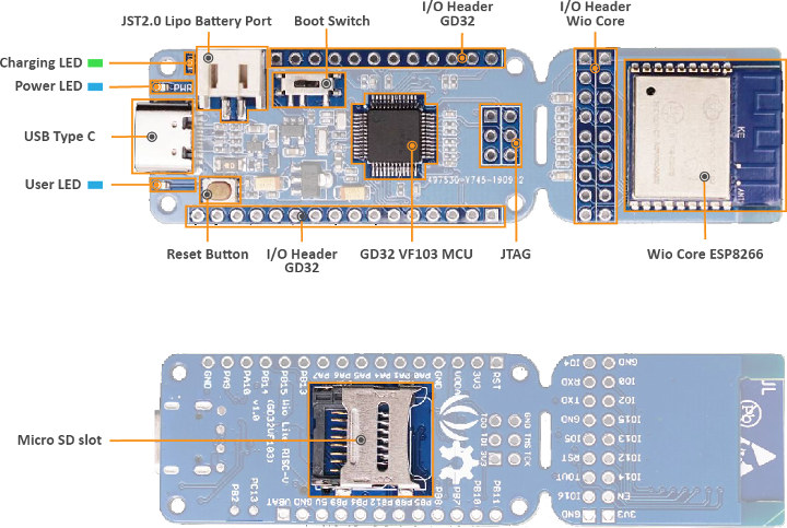
Wireless Module – ESP8266 Wi-Fi Wio Core with 802.116 / g / n / WiFi 4 connectivity
Microcontrolling Unit – Gigadevice GD32VF103CBT6 RISC-V at 108MHz with 32KB SRAM and 128KB Flash .
USB – One USB Type-C port for power and programming
MISC – Charging and power LEDS, boot switch and reset button
Storage – Micro SD card slot for storage
Debugging – Unpopulated 6-pin JTAG header
Power Supply – 5V via USB Type-C port and JST2.0 Lipo battery header .
Power Consumption – RISC-V core power consumption.
I / O header for Wio Core ESP8266 module and I / O headers for GD32 MCU
RISC-V-WiFi-Board
The board works with the Grove Shield for Wio Lite, so any Grove sensor or module can be used with it, just like in the Arm-based Wio Lite W600 which sells for $9.95. It is particularly ideal for battery operated devices and interesting to those that would want to work around with the RISC-V.
The Wio Lite RISC – V board is currently up for pre-order for $6.90 and shipping is expected to commence by the end of November. However, since the RISC-V board consumes less TBC than its counterparts and has an included battery support, there is a more likelihood that maybe by next year, RISC-V WiFi and Bluetooth boards would start selling for $2 or less.
For now, there is no documentation on it as such, but you can visit Github for some images, the PCB layout and the PDF schematics. More documentation would eventually be made available at Seeed Studio’s Wiki.