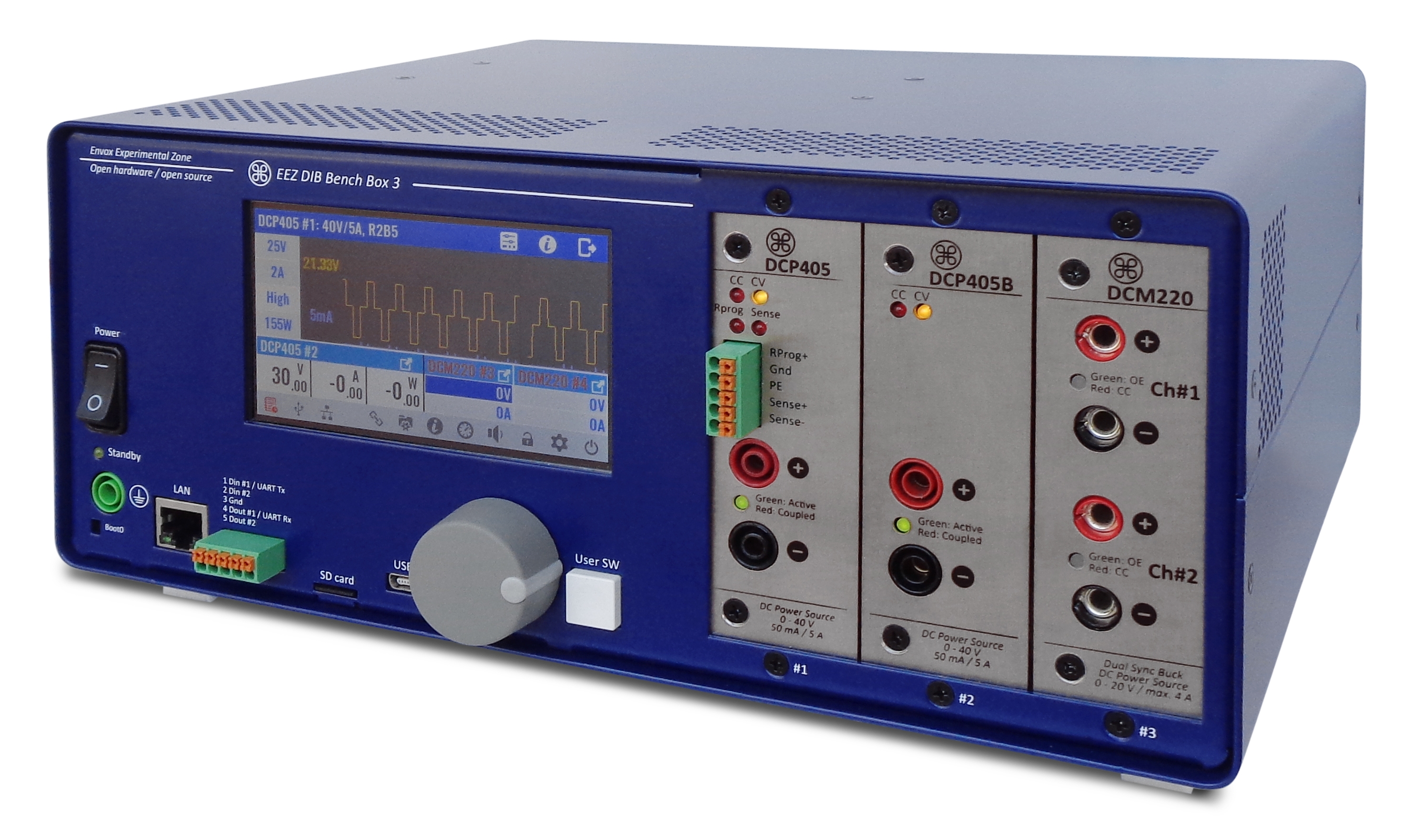
EEZ teams recently announced their latest project; the EEZ Bench Box 3 (BB3). The Bench Box 3 which is a FOSS and open hardware programmable power supply concept was designed to serve as a successor to EEZ’s H24005, with the aim of providing a power supply with better modularity, higher capacity, and functionality while preserving openness, and rich software support, all at a reasonable level of complexity so it can be built by anyone with intermediate electronics and soldering skills.
The BB3 comes with increased capacity compared to the h24005, starting from the color TFT display. The EEZ H24005 is one of the first programmable power supplies to incorporates color TFT touchscreen display but the BB3 not only also comes with a TFT display, it comes with an even larger display (4.3” 480×272 pixels) with antialiased fonts and larger menu options area improve legibility and simplify interaction. The touchscreen convenience on the BB3 is further expanded with accompanied incremental encoder that can be used for functions that are traditionally performed with push buttons or rotating knobs (e.g. changing output parameters).
The BB3 also comes with a larger number of modules (three instead of two) compared to the H24005 and is available for both single and dual-channel modules which allows configurations with up to six power outputs. The design of the BB3 was done with modularity in mind to allow easy upgrades in the future via the introduction of new peripheral modules to provide various functionality to users. Howbeit, it initially offers three different type of peripheral modules that can serve various user needs at varying budgets.
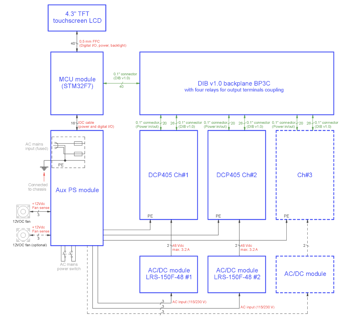
Modularity which is one of the key/interesting features of the BB3 was accomplished using the EEZ DIB (short for DIY Instrument Bus) concept created by the EEZ team. Currently in its first version, the DIY Instrument Bus(DIB) concept offers a simple way of interfacing a “master” module with up to three peripheral T&M modules connected via separate (dedicated) SPI buses. The master module is CPU-agnostic, therefore any MCU, CPU, FPGA, SoC, etc., with SPI capability can be deployed as main processing resource. The peripheral modules in the DIB concept are allowed to have there own EEPROM to store peripheral specific data and on-board processing resources that communicate with the master module. More on the DIB can be found on the project page.
The EEZ team’s plan is to design new modules alone or in cooperation with other teams that already successfully launched open hardware T&M devices. The new 2-quadrant and 4-quadrant power modules can be expected in the near future but planned functionalities go beyond DC power modules with the introduction of a power analyzer, signal/function generator, data acquisition module, thermal sensor module, stepper/DC motor controller, I/O and switch matrix, and much more. The initial investment in the BB3 will be preserved and the same is the case with accompanied software and firmware features.
Minimalist wire harness for simplified assembling and servicing
Up to 3 peripheral modules
STM32F7 ARM 32-bit MCU (2 MB Flash)
Color 4.3” TFT touchscreen display (8 MB SD-RAM for frame buffering)
Front panel AC power switch
Front panel bootloader switch for main MCU (firmware upload via USB DFU)
Incremental encoder and user-defined switch
USB 2.0 OTG and 10/100 Mbit/s Ethernet connectivity
Four power relays for various power outputs coupling
Dedicated full-duplex SPI for each module
Dedicated bootloader control for each module (firmware upload via UART, SPI or I2C)
Low noise Ø80 mm cooling fan with speed control
Remotely controlled by 300+ SCPI commands using the EEZ Studio of similar SCPI controllers
Compact size: 290 (W) x 123 (H) x 240 (D) mm
Max. weight (populated with three DCP405 and AC/DC power modules): 4 kg
BB3 Power Module Features
DCP405
DCP405B
DCM220
Number of Outputs
Single
Single
Dual
Floating Outputs
Yes
Yes
Yes (with on-board common GND)
Topology
Buck pre-regulator with linear post-regulator
Buck pre-regulator with linear post-regulator
Sync buck with CV/CC controls
On-board MCU
No
No
STM32F373
Voltage Range
0 – 40 V
0 – 40 V
1 – 20 V
Current Ranges
2
2
1
Current Range
0 – 50 mA / 0 – 5 A
0 – 50 mA / 0 – 5 A
0 – 4 A
Max. Power
155 W
155 W
140 W
Voltage Programming and Readback Resolution
5 mV
5 mV
10 mV
Current Programming and Readback Resolution
5 µA / 0.5 mA
5 µA / 0.5 mA
20 mA
Remote Sensing
Yes
No
No
Remote Sensing Reverse Polarity Protection
Yes
n/a
n/a
Remote Programming
Yes
No
No
Down-Programmer
Yes
No
No
HW (crowbar) OVP
Yes
No
No
SW Protections
OVP / OCP / OTP / OPP
OVP / OCP / OTP / OPP
OVP / OCP / OTP / OPP
Reverse Polarity Power Output Protection
Yes, fused
Yes, not fused
Yes, not fused
Outputs Coupling
Common GND / Split rails / Series / Parallel
Common GND / Split rails / Series / Parallel
Common GND
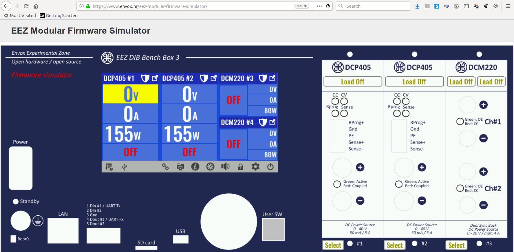
Openness and rich software suite is a distinguishable feature of all EEZ projects. The BB3 comes with feature-rich software and firmware, and some unique features of the EEZ software suite introduced with H24005 project, including; the fully featured simulator, in-house developed visual editor, SCPI controller/console, and TFT MHI, are also available for use with the BB3.
The simulator which runs as web application, allows the exploration of all firmware features and others like assigning virtual load on the module power outputs even when you don’t have a physical device at your disposal.
Web Simulator
The visual editor is a part of the cross-platform EEZ Studio that enables the rapid development of HMI for the BB3 color TFT touchscreen display. The EEZ Studio is capable of generating source code that can be directly imported into a firmware project and compiled (e.g. free ST Atollic TrueSTUDIO or STM32CubeIDE). The other part of the EEZ Studio is the SCPI controller application that allows users access BB3 in an intuitive way using the simple text-based SCPI commands. Leveraging on the capacity of the SCPI controller, the EEZ Studio facilitates fast and accurate collection of data like; the instrument’s screen data, logged data, control of inputs and outputs, parameter settings. Each instrument has it’s own “session window” and all interaction are stored in SQL database for efficient searching, presentation and archiving.
The BB3 displays continuity of the practice of the EEZ team to design their devices in a manner that ensures it can be easily replicated by DIYers/makers with intermediate skills in soldering, assembling, testing and have basic understanding of software and firmware installations and uploading. Although it includes custom made enclosure, builders have a freedom to make his/her own enclosure or adopt some general purpose enclosure of similar dimensions.
In line with EEZ team’s open source policy, the project is open source and the Schematics, Gerbers, mechanical drawings, BOM and code are all available on the Project’s GitHub repository, and are offered under TAPR license. Components used in the development of all the modules used in the BB3 are readily available from major suppliers and ordering codes for five different sources are added for every component in the BOM to make it easy to purchase them. Components in packages that require additional assembly equipment and skills (e.g. QFN, BGA) are omitted.
Forthcoming crowdfunding
The EEZ team is in the final stage of preparations for a crowdfunding campaign for the BB3 Project. The campaing will offer the BB3 in a highly completed and tested (Almost-Ready-To-Run) Kit form and backers will be able to choose between multiple configurations starting from bare PCBs set, custom enclosure to the fully-featured configuration with multiple power outputs.
The EEZ team also told us that they’re working on fully assembled, tested and calibrated solution that is expected to be ready for shipment next year with required certificates for the EU and the US markets.
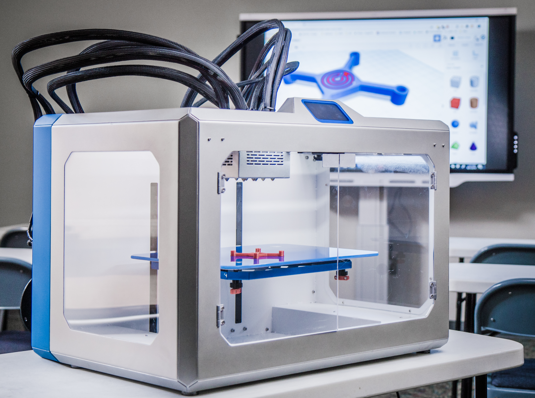
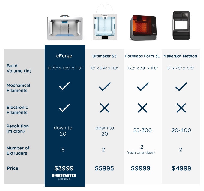
Today, ELECTRONIC ALCHEMY , a startup that emerged from university research launched a crowdfunding campaign for their eForge electronics 3D Printer. It is designed for makers, students and professionals and is now available on Kickstarter starting at the super early bird price of $3,999.
eForge is the first electronics 3D Printer that prints on demand new proprietary filaments that were developed from research sponsored by NASA. It also prints standard filaments like ABS and PLA with precision. The team led by Dr. Chance Glenn has developed an easy-to-use tool that can print up to 8 multi-materials.
“eForge is a tool to enable creativity. Imagine what people can do once they realize the power they will possess with this product. I can’t wait to see it.” ~Co-Creator, Dr. Chance Glenn
This new standard for printing collaborated with Autodesk to utilize a platform that takes standard modeling files like .stl or .obj,, then with a gcode slicer it can print virtually any 3D printer filament. Additionally, the multi-material extruder system uses automatic lifting smart nozzles to control contamination in every print.
The only 3D Printer that prints electronic materials
Achieves precision and speed with modified Bowden extruder system
Compact and contained to fit in workshops, classrooms and studios.
eForge’s Kicks tarter campaign runs from October 15 to November 21. For a full rundown of the pledge levels visit their Kickstarter page. Media wishing to interview their personnel should contact Ms. Latonia Jones at media@electronicalchemy.com
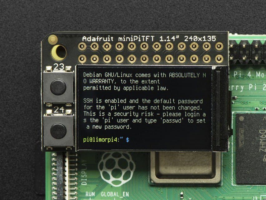
The Adafruit Mini PiTFT – 135×240 Color TFT Add-on for Raspberry Pi is your little TFT pal, ready to snap onto any and all Raspberry Pi computers, to give you a little display. The Mini PiTFT comes with a full color 240×135 pixel IPS display with great visibility at all angles. The TFT uses only the SPI port so its very fast, and we leave plenty of pins remaining available for buttons, LEDs, sensors, etc. It’s also nice and compact so it will fit into any case.
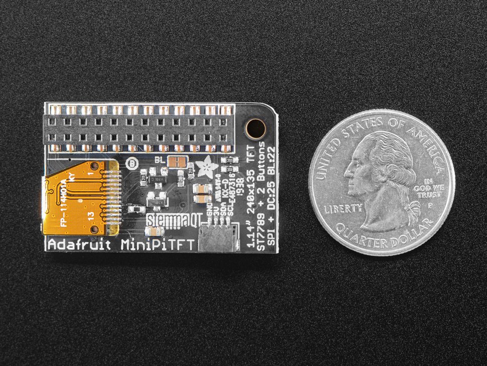
This display is super small, only about 1.14″ diagonal, but since it is an IPS display, its very readable with high contrast and visibility. We had a little space on the top so we give you two tactile buttons on GPIO pins so you can create a simple user interface.
Using the display is very easy, we have a kernel driver and Python library for the ST7789 chipset. You can set it up as a console output so you can have text and user interface through the Raspberry Pi OS or you draw images, text, whatever you like, using the Python imaging library. Our tests showed ~15 FPS update rates so you can do animations or simple video.
Comes completely pre-assembled and tested so you don’t need to do anything but plug it in and install our Python code! Works with any Raspberry Pi computer.
www.hackster.io writes:
Despite its name, the Mini PiTFT isn’t the smallest Raspberry Pi display Adafruit has ever designed: The earlier PiOLED used a monochrome organic light-emitting diode (OLED) display panel measuring just 1″ diagonal, but with a somewhat restricted 128×32 resolution. The follow-up OLED Bonnet doubled the vertical resolution to a 128×64 total, but at the cost of a larger 1.3″ diagonal.
The Mini PiTFT is now available on Adafruit, and soon from the company’s international distribution partners, priced at $14.95.
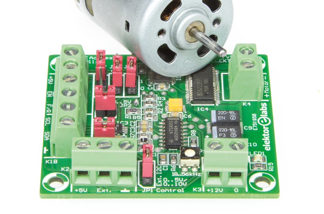
This control circuit will provide the correct rotational speed and direction of a 12-V DC motor. Nothing special in that? But there is definitely, when you consider the multitude of potential options for actuating the motor. You can adjust the speed manually with a potentiometer (‘pot’), using a DC voltage level between 0 and 5 (or 10 V) or even digitally using I2C.
Go to the article page and download a pdf copy of this back article. Downloading is free to all Elektor e-zine subscribers.
Original publication: Elektor magazine 3 / 2016 (May & June).
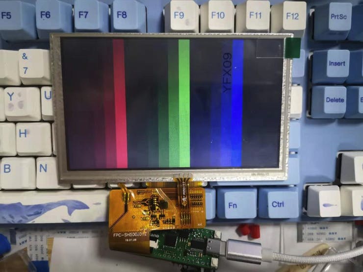
FPGA Boards have grown to become one of the “favorites” of the Embedded community. They feature in all kind of applications ranging from automation to DIY Applications, however, typical FPGA boards still cost way more than some other popular boards like the Arduino Microcontroller boards (even though performance is incomparable!). This keeps FPGA boards out of the reach of a good section of the community and to solve this, Sipeed, an open source hardware and embedded computing specialist, recently announced the final specifications for their ultra-low-cost FPGA development board called; the Tang Nano, which according to the firm is expected to cost less than $5.
The Tang Nanos were originally planned by Sipeed to cost only $3 as revealed in an earlier tweet on the company’s Official Twitter handle, but were later estimated at “less than $5 ” by the company in another tweet. While no official specifications was released during the first announcement as only a picture of the board connected with a full-colour liquid-crystal display panel using an on-board display output was included, the announcement generated quite the buzz and led to a lot of people pitching in several ideas and recommendation. Adding support for the suggestions received will no doubt have caused the need for additional components, etc., and most likely be the reason behind the increase in cost.
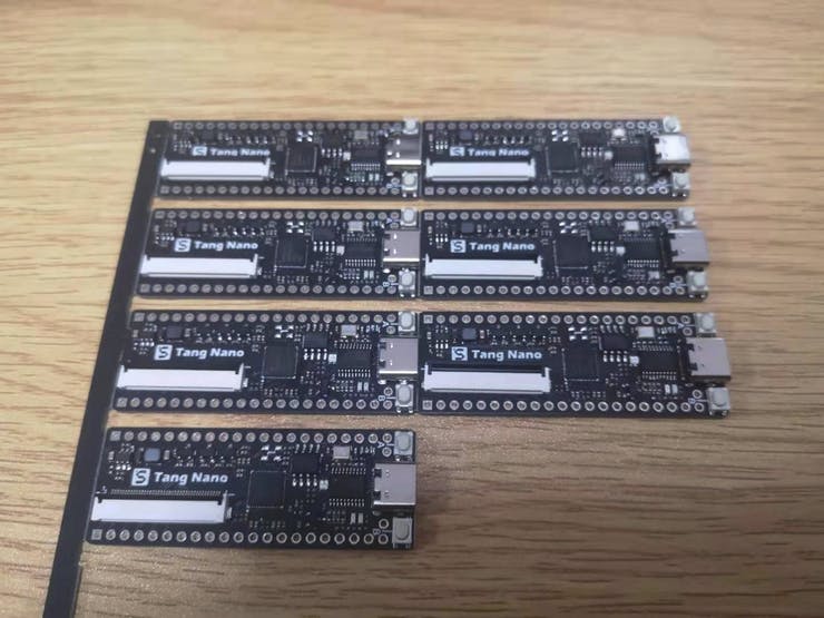
In the Twitter update, after revealing the slight increase in cost, the company revealed pictures of the first mass-produced models along with final specifications which include; 1,152 four-input lookup tables (LUT4s), 72Kb static RAM (SRAM), 64Mb pseudo-static RAM (PSRAM), an on-board RGB LED, 40-pin RGB LCD display interface, and on-board programmer with USB Type-C connectivity and that the board will be based on a Gowin Semiconductor 48-pin FPGA.
While a comprehensive official specification needs to be provided by the company’s before it can be verified, a mention on the tweet update that the board uses the “cheapest’ Gowin Semiconductor 48-pin FPGA could only mean that the board will be based on an FPGA from the GW1N-1 LittleBee family and this means we chould be expecting a 55nm low-power process node.
A picture of the board was also shared and one can clearly see that the board is based on the WCH CH552 serial-USB chip and other features like; the 21 pin headers arranged in a breadboard-friendly manner, the display connector, and a USB type-C connector which is fast becoming a standard for hardware devices.
Sipeed initially proposed September launch date for the board but it was missed and with no other launch date or any info on the commercial availability, it may be cool to shoot them an email or just stay glued to the company’s twitter account to get information on the board and also get notified as soon as it drops and is available for sale.
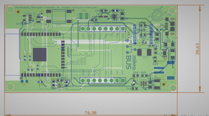
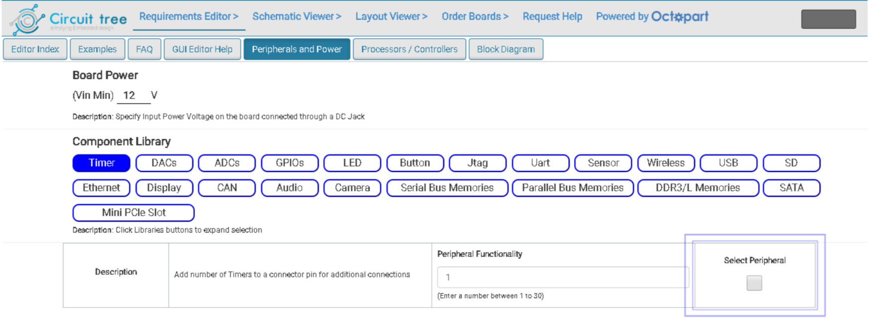
What if your PCB can be designed in just a few minutes, with you providing only the specifications and selecting the major components to be used? Circuit-Tree.com is making it a reality with their Intelligent Rapid Circuit Board Design Platform.
Creating Schematics and PCBs, is one of the major tasks associated with the design of any electronics product. For entreprenuers / innovators, it can be very costly, while for Hardware designers and engineers, it is a task they are familiar with but wish it takes less time to complete. This scenario describes the problem being solved by the Rapid Circuit Board Design platform recently announced by Circuit Tree. Through the Platform, designers can design Schematics, create the printed Circuit Board, and prototype using several Processor /Controller, network port, sensors and other hardware features they want in minutes.
The Circuit Tree platform uses the components selected and requirements specified (including Board size, PCB fabrication and add placement rules) by the user to generate an instant schematic and PCB with the smallest possible board size (or the specified board size), using a proprietary intelligent auto-placement algorithm.
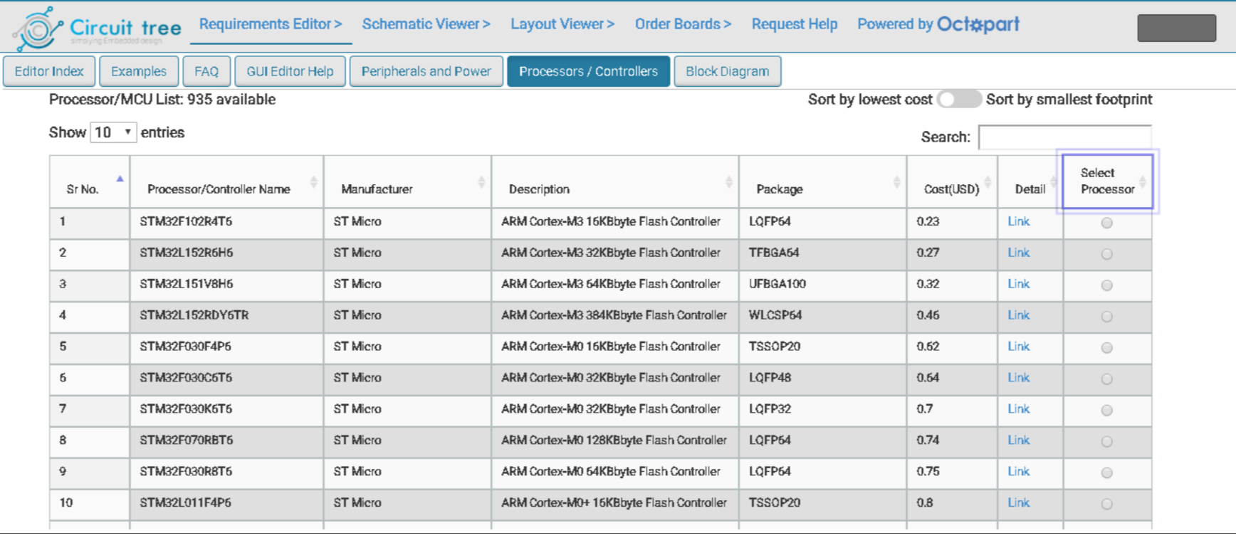
During the design process, users have the luxury of selecting from a constantly updated library of 900+ SOCs and other components from diverse manufacturers like STMicroelectronics, Texas Instrument, NXP, and Microchip to mention a few, to ensure you have what is needed by your project and provide diverse design options The platform also comes with various peripherals blocks which allows the addition of your own components along with features that allow users compare alternatives to a particular component in terms of features and costs.
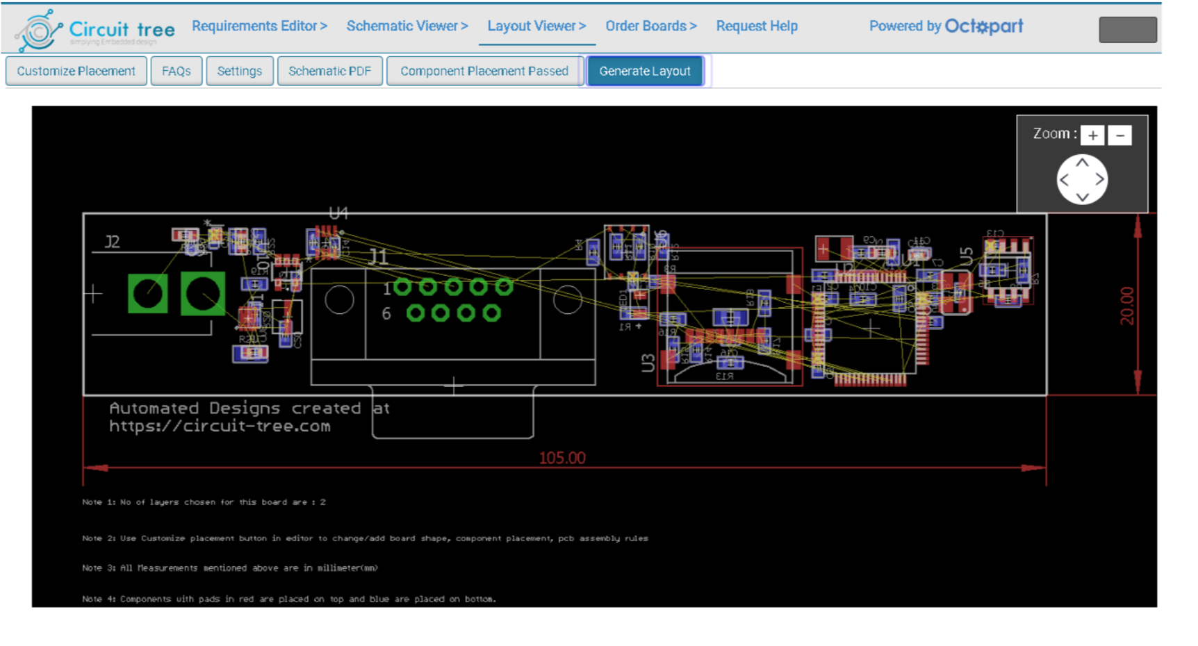
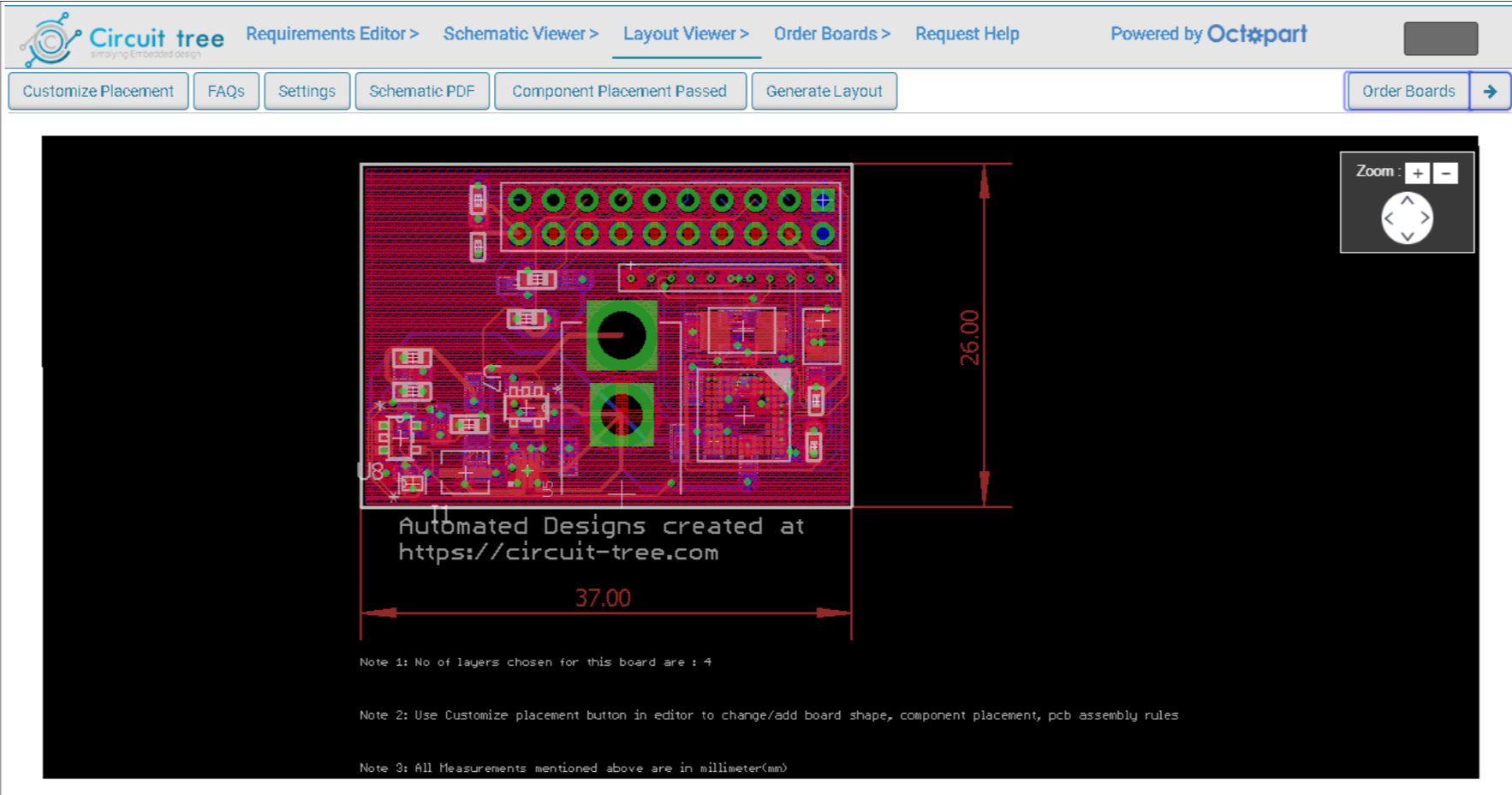
For PCB Design, the platform allows iteration with layer counts, component placement changes and much more when the layout is generated. It also intelligently handles popular PCB topics/issues like the fanout of BGAs, differential traces and length matching for high-speed signals.
Asides providing a platform that handles design of Boards, Circuit-Tree also handles board manufacturing and designers are not only able to go straight from design to order in 10 minutes, they can also get the physical, manufactured board in their hands in just 14 days (including shipping time).
All of these makes Circuit Tree an interesting solution designed with an understanding of the challenges of Hardware development. According to the Founder – Makarand Kapoor, the platform was developed to decrease-time-to-market and allow engineers and enthusiast focus on creativity. In his words, Makarand said,
” Engineers typically spend a lot of time in Component selection, Creation of schematic, placement of components, layout generation stages which need multiple iterations. Enthusiasts and engineers should continue to tap into powerful solution like these to decrease time-to-market and reduce engineering pain they go through. “
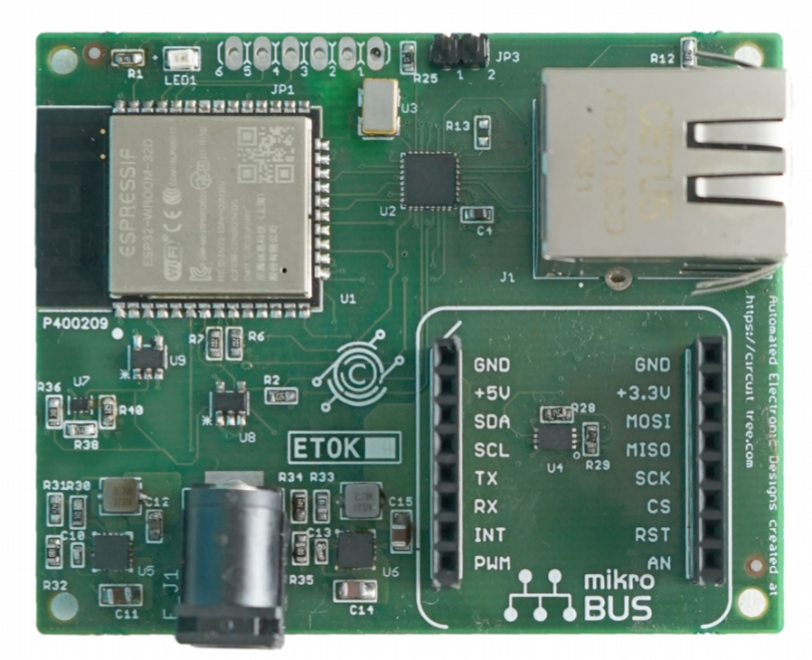
Circuit Tree has been used in the development of several development boards and two of those boards; The ESP32 gateway Board and the ESP32 Click board were recently released on Circuit Tree’s Store. The ESP32 gateway board is a palm-sized Ethernet enabled board based on the ESP32 module. It incorporates an Ethernet port and Connectors designed to be compatible with the Click form factor which opens the board to the use of 500+ different types of click boards. While also based on the ESP32 module, the “ESP32 Click Board”, on the other hand, was designed to serve as an end node as it comprises of a Click Board connector and is designed with features to support it as a battery powered board.
Both boards are available on Circuit Trees Online Store with the ESP32 gateway being sold for $35 while the ESP32 Click Module is sold $25.
As we move closer to a world with computers becoming ubiquitous and smarter with AI, I personally find the platform very interesting as it could one day (*putting on my futurist cap*) be the platform through which we issue voice commands to a computer and it creates the PCB we need.
Let’s Start Coding Offers Customizable Electronic Kits That Teach Kids 8-12 Real Code in a Hands-on Way
Remember how much fun you had with chemistry sets from your childhood? You made things blow up and glow and learned about chemistry in the process. Let’s Start Coding is the “chemistry set” for today’s kids, teaching them real-world coding skills while making cool toys and gadgets.
Let’s Start Coding kits are designed with the beginner in mind though they also make a great next step for kids who are familiar with Scratch, Blockly, Minecraft or Hour of Code. This holiday season, give the gift of coding skills– the same skills used by organizations like NASA and Microsoft– to your favorite young learner.
A kit from Let’s Start Coding contains customizable electronics, like LED lights, speakers, buttons, and sensors. Through our free online examples and projects, kids learn to manipulate these physical gadgets with C++ code, building devices and toys as simple as a flashlight or as complex as a mini video game. Recent users have built an LED belt, a gadget that lights up their skateboard, an automatic night light, a “Clapper”-like device, even a digital dj booth.
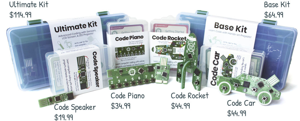
Let’s Start Coding has a lineup of 6 kits for the holiday season for the budding engineer or inventor in your life. Customizable kits are Speaker ($19.99), Piano ($34.99), Car ($44.99), Rocket ($44.99), Base Kit ($64.99), Ultimate Kit ($114.99). Kits are available on Amazon and at www.letsstartcoding.com.
UPDATE 24/11/2019: If you sign up for the Let’s Start Coding newsletter you’ll receive special discount codes and updates about their products. Sign up now to receive their biggest discount of the season, only for subscribers, the Wednesday before Thanksgiving.
With IoT expanding, developers are begining to desire more communication options to facilitate the exploration of diverse IoT possibilities. This was one of the reasons why the announcement of partnership between Chirp and Arduino was received with so much enthusiasm by the makers. Arduino has established itself as one of the biggest names in the ecosystem attached with its easy/ready to use hardware, while Chirp is arguably the most robust Data over Sound communication platform, as such, a lot of people believe the collaboration will not only bring Chirp’s functionalities into Arduino but it will also make the corresponding functionalities easy to use. For today’s tutorial, we will look at how you can implement Chirp’s Data over Sound communication in your Arduino Project.
Data over sound is the process of converting information into audible or inaudible frequencies that get transmitted with a speaker and that can be received with the help of a microphone and Chirp is currently one of the best ways to do it. The Chirp SDK encodes the message you want to send into a series of sounds that form an audio barcode that can be played back with any device that has a loudspeaker. Devices that have a microphone can then listen for these codes and decode them to restore the original message.
Chirp adds a completely unique transport mechanism to Arduino boards. The added capabilities of data-over-sound means that makers have more connectivity options at their fingertips. Some of the advantages of data-over-sound include:
Device agnostic: data can be sent from mobile apps, web pages, or even with just an audio file
One to many: any device within hearing range is able to receive data in one simple transaction
Frictionless: doesn’t need any pairing, passwords or initial setup
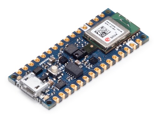
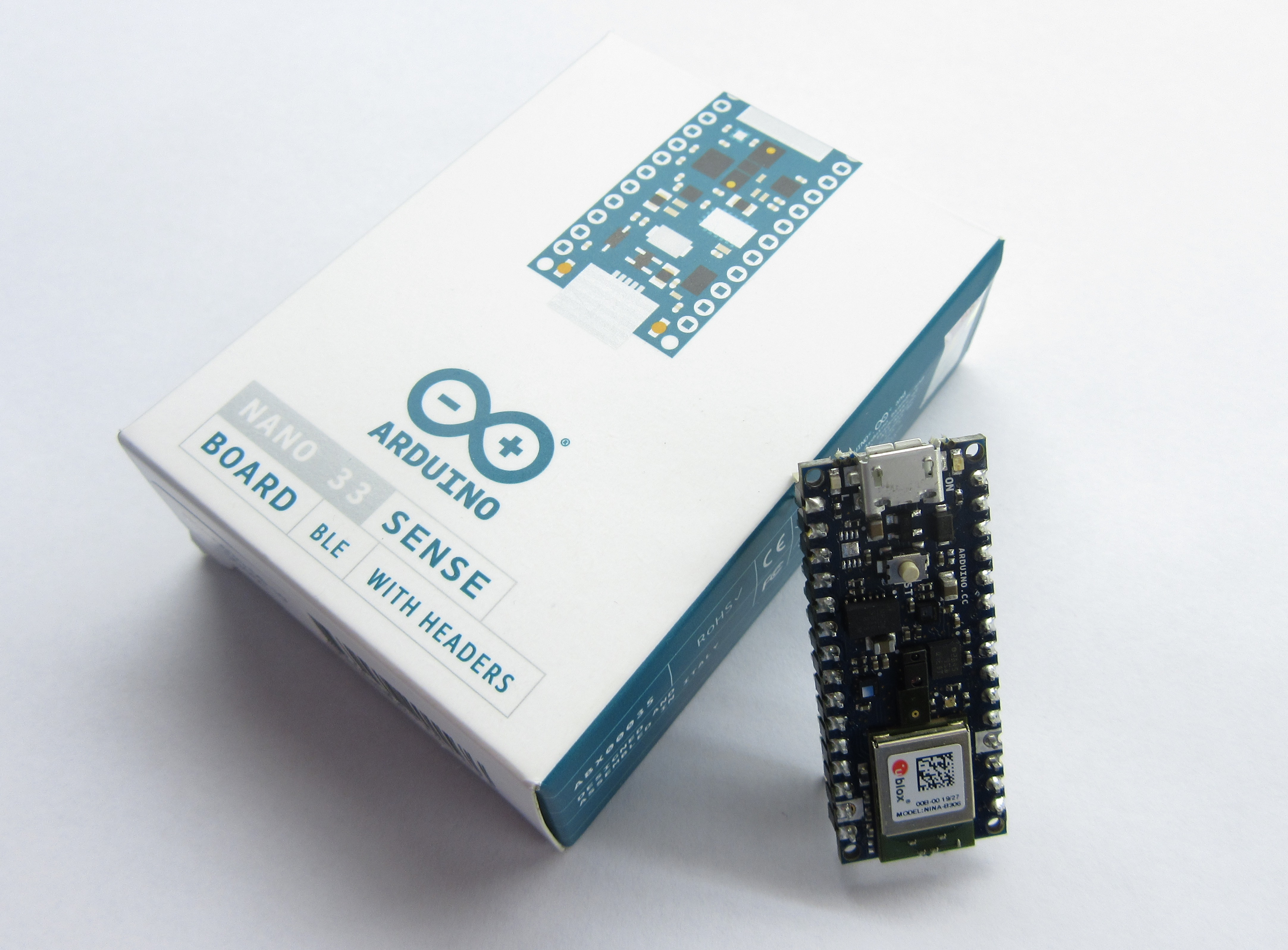
Nano 33 BLE Sense
To demonstrate how to use Chirp features with the Arduino, we will build a simple project which changes the color of an attached LED in line with an RGB value received via audio signal. For this project, we will use the new Arduino “Nano 33 Sense” board which is one of the latest Arduino boards with a wide range of onboard sensors and features including an onboard microphone that is optimized for Chirp.
Required Components
Everything we need for this tutorial including the RGB LED, and Microphone, comes with the Nano 33 Sense board, making it the only thing needed for the tutorial. However, to be able to better observe the change in color, you may decide to use an external RGB LED asides the one onboard. To do that, you will need:
The Nano 33 Sense Arduino Board
220 ohms Resistor
RGB LED
Breadboard
Jumperwires
The Nano 33 Sense Arduino board can be bought from the official Arduino Store or from several other vendors on Ebay and similar platforms.
Nano 33 Sense Arduino board
Schematics
Going with the onboard RGB LED means you do not need to worry about schematics or connections as everything you need including the mic and the LED already comes with the board.
Getting Ready
Before we write the code for the project, we need to sign-up to Chirp to obtain the necessary credentials like the app key, the app secret and audio configuration as they will be required for our code.
Follow the steps below to complete your chirp sign up and obtain necessary details. If you have a Chirp account already, you can jump to step 3.
On the resulting page, Choose the sign in with Google option or just fill in the details and hit the sign up button at the end of the page.
With sign up complete, you will be automatically directed to a “configure your application” page. This page is where you choose which of the Chirp protocol you will use for your project and the app key, secret and config will be automatically generated. Chirp currently supports 5 protocols with different audio transmission properties but for this tutorial, we will use the 16khz-mono-embedded protocol as it is the one currently supported for Arduino. Select it from the drop-down menu under the configuration section and click on the SAVE button.
Your APP key, APP secret, and Configuration should now be generated. Copy them to a safe place as we will use them in the Arduino Sketch.
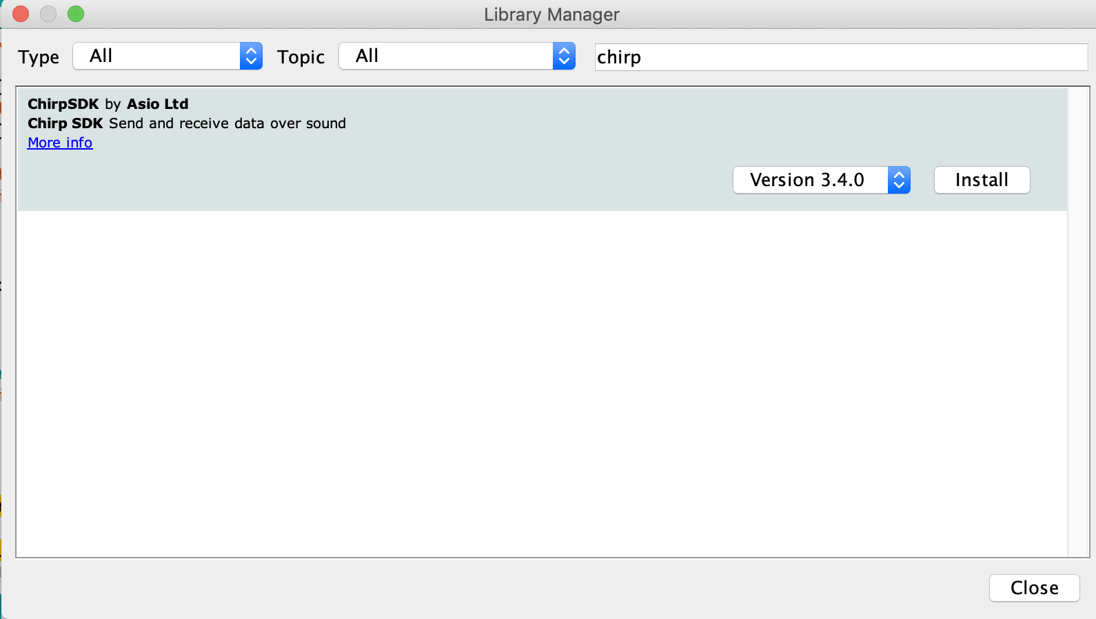
Another thing we need to do is to prepare the Arduino IDE by installing the Chirp SDK on it. Go to the Arduino Library manager (via Tools -> Manage Libraries) and enter “Chirp SDK” in the search bar. You will see the SDK listed as shown below.
Click the install button and close the manager when done.
We are now ready to write the code for the project. However, ensure you are using the latest version of the IDE as older versions may not come with the Nano 33 Sense board installed although it can be installed via the IDE board manager.
Code
The code for this project is a modification of the receiver example attached to the Chirp SDK we installed earlier.
The thought process behind the code is simple. The devices stay on the lookout for audios matching that of its protocol. When the matching sound is received, it evaluates it and extracts the message stored in it. The message, which in this case is an RGB value, is then used to set the color of the connected (onboard) RGB LED.
Asides the Chirp SDK which we mentioned earlier, we will also use the PDM (Pulse Density Modulation) library. The PDM library will be installed when adding the Nano 33 Sense board via Boards Manager and makes it easy to work with PDM microphones like the MP34DT05 onboard the Nano 33 Sense.
As usual, I will do a brief explanation of the sketch, explaining sections I feel might be difficult to understand. We start the sketch by including these libraries mentioned above along with the Credentials.h file. The credentials.h file should be located in the same folder as your code. Ensure the chirp credentials we obtained earlier are filled accurately in it.
Next, we create variables to indicate the audio sampling rate, buffer size and pointers to the pins of the Nano 33 Sense in which the RGB LED is connected.
Next, we write the Void setup() function. We start the function by initializing the serial port so the serial monitor can be used for debugging. We follow that up by setting the pinMode of the three pins to which the RGB LED is connected as output.
Next, we enable the high-frequency oscillator on the board. This is done to ensure the clock is accurate across different boards.
// Enable high frequency oscillator
  NRF_CLOCK->EVENTS_HFCLKSTARTED = 0;
  NRF_CLOCK->TASKS_HFCLKSTART    = 1;
  while (NRF_CLOCK->EVENTS_HFCLKSTARTED == 0);
Next, we initialize Chirp communication by calling the setupChirp() function, initialize the PDM library by calling the onPDMdata() function whenever sound is received (PDM.onReceive()), and set the gain property of the microphone. The onPDMdata function is used to sample the received audio with the output stored in the samplesRead variable.
Next, the microphone is tested in such a way if the test fails, the code stays static in an unending while loop. This helps with debugging as it makes it easy to identify when the mic is bad.
if (!PDM.begin(1, SAMPLE_RATE))
{
  Serial.println("Failed to start PDM!");
  while (1);
}
Finally, we write maximum values to all the pins of the RGB LED and move to the void loop() function.
The void loop() function is quite simple. We run a check to see if samples have been read, if yes, the Chirp_connect_process_shorts_input() function is called to process the received audio and the response of the function is passed into the chirpErrorHandler() function. The samplesRead variable is then reset to zero.
While the void loop() presents a very simple code structure, it is important to note that there are several functions associated with the commands within it. Some of those functions includes the setupChirp() which was called under the setup function and the onReceivedCallback() function.
The setupChirp() function is at the heart of the Chirp Data over Sound implementation. It takes in the app key and app secret obtained earlier and uses them to initialize Chirp communication. It also contains several callback sets which are used to determine what happens when a message is sent or in the sending process and when a message is received or being received. This call back makes it easy to perform actions and state what happens at every point during communication.
The onReceivedCallback function is the callback assigned to onReceived callback set in the setupChirp() function. It decodes the sound received and writes the values contained in it to the RGB LED pins.
void onReceivedCallback(void *chirp, uint8_t *payload, size_t length, uint8_t channel)
{
  if (length)
  {
    // High values mean lower brightness, so we
    // subtract from UINT8_MAX
    analogWrite(R_LED_PIN, UINT8_MAX - payload[0]);
    analogWrite(G_LED_PIN, UINT8_MAX - payload[1]);
    analogWrite(B_LED_PIN, UINT8_MAX - payload[2]);
  }
  else
  {
    analogWrite(R_LED_PIN, 0);
    analogWrite(G_LED_PIN, UINT8_MAX);
    analogWrite(B_LED_PIN, UINT8_MAX);

    delay(500);
    analogWrite(R_LED_PIN, UINT8_MAX);
    delay(500);

    analogWrite(R_LED_PIN, 0);
    Serial.println("Decode failed");
  }
}
Other functions used in the sketch include the onReceivingCallback() to flash the LEDs in a particular manner when data is being received and the chirpErrorHandler() which displays errors in human-readable formats.
With the code complete, connect the Arduino Nano 33 Sense to your computer, select the board type and port, and hit the upload button.
To test the project, we will use the following prerecorded chirp files:
Red: Play this to change the color of the RGB to red.
Green: Play this to change the color of the RGB to Green.
Blue: Play this to change the color of the RGB to Blue.
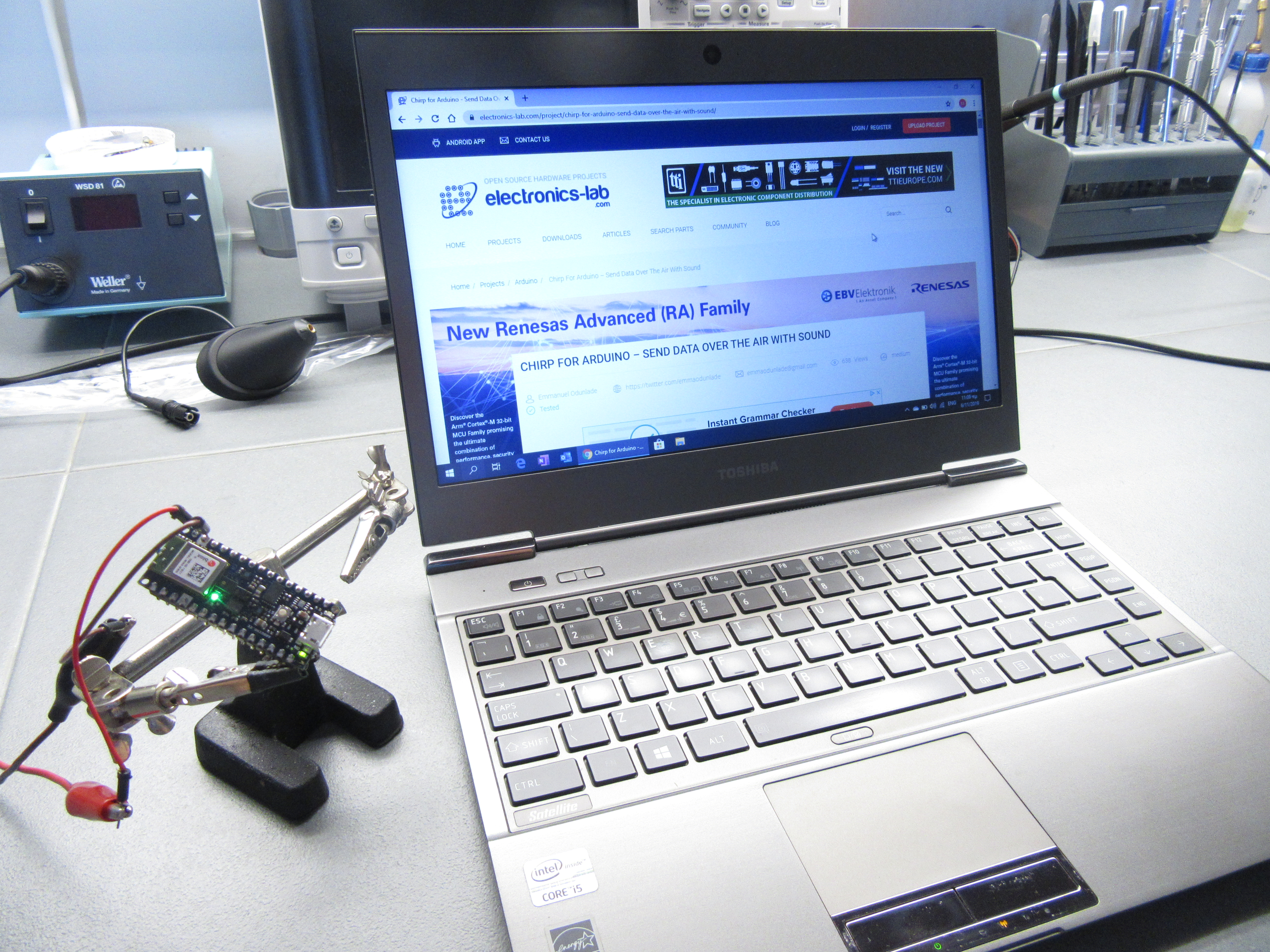
Play any of these sounds within the audible range of the board and you will see the LED change to the color contained in the audio as shown below.
Chirp demo setup
Instead of these prerecorded sounds provided by Chirp, you can decide to build another project which in place of the mic, will come with a speaker to broadcast the commands, so today’s project serves as the receiver. You can also develop your own sound command following the Audio API or play a random chirp from the applications page on the developers website.
Demo Video
Data over sound is one of the hottest research topics currently due to the possibilities it holds around redefining the way devices communicate. With breakthroughs like Chirp’s Ultrasonic protocols (which will hopefully come to Arduino soon), devices will be able to communicate using non-audible sounds. This means commands could be embedded in songs without the “weird” bird sounds and so on.
That’s it for this tutorial guys. Do reach out to me via the comment section if you have any questions or are facing any challenges with this project.
Resources used for this project are from Chirp’s documentation on the usage with Arduino. You can check it out to learn more.
Graduate researchers at the City College of New York have demonstrated a LED based on half-light half-matter quasiparticles in atomically thin materials. By Julien Happich @ eenewsled.com
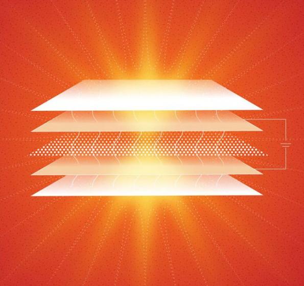
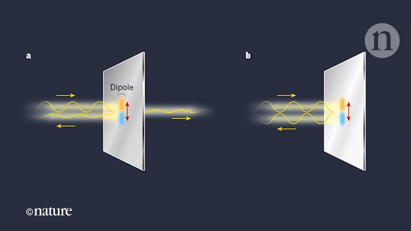
This is also the first successful test of an electrically driven light emitter using atomically thin semiconductors embedded in a light trapping structure (optical cavity), the researchers claim in a paper titled “A room-temperature polariton light-emitting diode based on monolayer WS2“ published in Nature Nanotechnology.
While such LEDs have been realized in other materials at low temperatures, this device operates at room temperature and is fabricated using the now well known “scotch tape” based technique
Schematic of a half-light- half-matter quasiparticle based LED developed in Vinod Menon’s group using atomically thin materials. Image credit: Visakh Menon
“The fact that this device is fabricated using stacks of atomically thin materials and operates at room temperature makes it an important first step towards a technologically relevant device demonstration,” noted Vinod Menon, chair of physics in City College’s Division of Science and the research team’s mentor. “One potential application of such hybrid LEDs is the speed of operation which can translate to using them for LED based communication systems including LiFi”, Menon added.
The device was fabricated at the CCNY-based CUNY Advanced Science Research Center’s nanofabrication facility and tested in Menon’s lab. In follow- up research, the CCNY team is attempting to realize quantum emitters (single photon emitters) using a similar architecture.
As such for any electronic circuit, the behavior of amplifiers is affected by the frequency of the signal on their input terminal. This characteristic is known as the frequency response.
Frequency response is one of the most important property of amplifiers. In the frequency range that amplifiers have been designed for, they must deliver a constant and acceptable level of gain. The frequency response depends directly on the components and the architecture chosen for the design of the amplifier.
In this tutorial, we will focus on this important feature of amplifiers. First of all, the notion of frequency response is detailed along with some basic related concepts and we will present how to quantify it. In the second section, we will understand which component affects the frequency response and how. In the rest of the article a method to establish the low and high frequency responses is presented. These results will finally be synthesized in the conclusion to plot the global frequency response of a Common Emitter Amplifier.
Definitions
Before defining in details the frequency response, we need to present the unit of decibel (dB) and the logarithmic scale related to it. When studying the frequency response, it is indeed more suitable to convert either the power or voltage gain into dB and to represent the frequency scale in a logarithmic (log) scale.
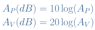
If we consider an amplifier with power gain AP and voltage gain AV, the power and voltage gain in dB are defined by :
eq 1 : Power and voltage gain in dB
While the gains in linear scale are always positive (AP,AV≥0), their equivalent in dB can either be positive if an amplification is being realized (AP,AV>1) or negative if the input signal is attenuated (AP,AV<1).
Often, it is not the gain AV(dB) that is investigated but rather a normalized ratio AV/AV,mid(dB)=20log(AV/AV,mid). Where AV,mid is called the midrange gain and represents the maximum gain of the amplifier in its frequency working range, for example 20 Hz – 20 kHz for an audio amplifier.
Therefore, when AV=AV,mid, the normalized gain (written indifferently AV) is AV(dB)=0. This sets a 0 dB reference when the gain is maximum. It is important to note that when the power is divided by two, we observe that AP(dB)=10log(0.5)=-3 dB.
The frequency at which the power drops to 50 % of its midrange value is known as the cutoff frequency and noted fc. Each time that the power is halved, a reduction of 3 dB of the normalized gain is observed. Therefore AP=-3 dB corresponds to AV,mid/2, AP=-6 dB corresponds to AV,mid/4 and so on …
For this same frequency, the voltage (or current) is multiplied by a factor √2=0.7. Halving the voltage signal corresponds to a reduction of 6 dB and follows the same pattern as presented for the power gain.
The most common tool used to represent the frequency response of any system is the Bode plot. It consists of the normalized gain AV(dB) as a function of the frequency in log scale. A simplified Bode graph of an amplifier is shown in the Figure 1 below :
fig 1 : Typical Bode graph of an amplifier
The light blue curve is called the asymptotic representation while the dark blue curve is the real frequency response of the circuit.
In Figure 1, two different cutoff frequencies can be distinguished : flc for “low cutoff” and fhc for “high cutoff”. The quantity fhc-flc is called the bandwidth and represents the frequency range where the gain is above the -3 dB plateau.
One last observation can be given about the slope of the frequency response out of the bandwidth. First of all, they are not necessary identical for low and high frequencies. Moreover, as we will see later, the slope has a value that depends on the reactance of the components that induce a dependency with the frequency.
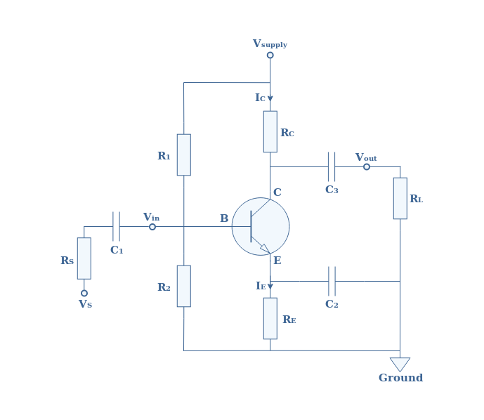
The structure around the BJT transistor consists of a voltage divider network (R1 and R2), a load (RL), coupling capacitors (C1 and C3) and a bypass capacitor C2.
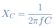
What is important to keep in mind is that capacitors have a property called reactance that is an equivalent of the resistance. The reactance (XC) of capacitors depends on the frequency and the value of the capacitor, it satisfies the following formula :
eq 2 : Reactance of capacitors
Independently of the value of the capacitor, when the frequency is low, XC tends to be high. Near DC signals, capacitors behave therefore as open circuits. On the other hand, when the frequency increases XC tends to zero and capacitors act as short circuits.
At low input frequencies, the coupling capacitors will more likely block the signal, since XC1 and XC3 are higher, more voltage drop will be observed across C1 and C3. This results in a lower voltage gain.
At high input frequencies the bypass capacitor C2 shortens the emitter branch to the ground and the voltage gain of the amplifier is AV=(RC//RL)/re with re being the small diode emitter resistance. When the frequencies are lower, the resistance between the emitter and the ground is no longer only re but RE+re and therefore the voltage gain decreases to AV=(RC//RL)/(RE+re).
There is another type of capacitors that affect the frequency response of the amplifier and is not represented in Figure 2. They are known as internal transistor capacitors and represented in Figure 3 below :
fig 3 : Internal transistor capacitors
Whereas the coupling and bypass capacitors act as high-pass filter (they block low frequencies), these internal capacitors behave differently. Indeed, if the frequency is low, CBC and CBE act as an open circuit and the transistor is not affected at all. However, if the frequency increases, more signal passes through them instead of going in the base branch of the transistor, therefore decreasing the voltage gain.
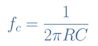
A very important formula is given in Equation 3 and links the cutoff frequency of a RC filter :
eq 3 : Cutoff frequency of a RC filter
Low frequency response
Having all of this information in mind, let’s calculate and plot the low frequency response of the CEA of Figure 2 with the below given parameters :
First of all we consider the input high-pass filter RinC1. As explained in previous tutorials, Rin is the total input impedance of the amplifier. In our example, it can be determined by ]
Rin=RS+(R1//R2//βRE)=20.2 kΩ.
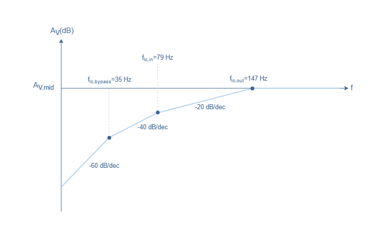
The low cutoff frequency of the input will therefore be : fcl,in=1/(2πRinC1)=79 Hz.
The same procedure can be done for the output where the output resistance is Rout=RC//RL=2.7 kΩ. The low cutoff frequency of the output filter is : fcl,out=1/(2πRoutC3)=147 Hz.
Finally, for the bypass capacitor, the resistance formula is more complex and given by Rbypass=RE//((re+(RS//βRE)/β))=30 Ω. The low cutoff frequency of the bypass structure is thus :
fcl,bypass=1/(2πRbypassC2)=35 Hz.
One last thing we need to understand before plotting the Bode graph is about the slope out of the midrange values. The decrease of AV,mid with the frequency is called roll-off and its value for each simple RC filter is -20 dB/decade (dB/dec). This value means for high-pass filters (resp. low-pass filters) that each time the frequency is divided by 10 (resp. multiplied by 10), a decrease of -20 dB is observed for the gain of the amplifier.
When multiple filters are blocking the same range of frequencies, the roll-off is enhanced. In our example three filters are simultaneously blocking the frequencies below 35 Hz, the roll-off is therefore 3*(-20 dB/dec)=-60 dB/dec.
This information can be synthesized in a Bode plot showing the low frequency response of the CEA in asymptotic representation :
fig 4 : Low frequency response of the CEA
High frequency response
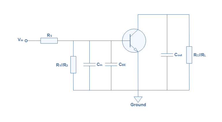
As stated previously, it is the internal transistor capacitors that will limit the gain at high frequencies acting as low-pass filters. It can be shown that the equivalent circuit of Figure 2 at high frequency can be drawn such as presented in Figure 5 :
fig 5 : Equivalent CEA at high frequency
We can note that the coupling capacitors are not represented since they behave as short circuits at high frequencies. Moreover, the emitter branch is shorten to the ground for the same reason applying to the bypass capacitor.
The internal capacitor CBC is converted via Miller’s theorem into the equivalent Cin and Cout capacitors. Moreover, this theorem states that Cin=CBC(AV,mid+1) and Cout=CBC(AV,mid+1)/AV,mid.
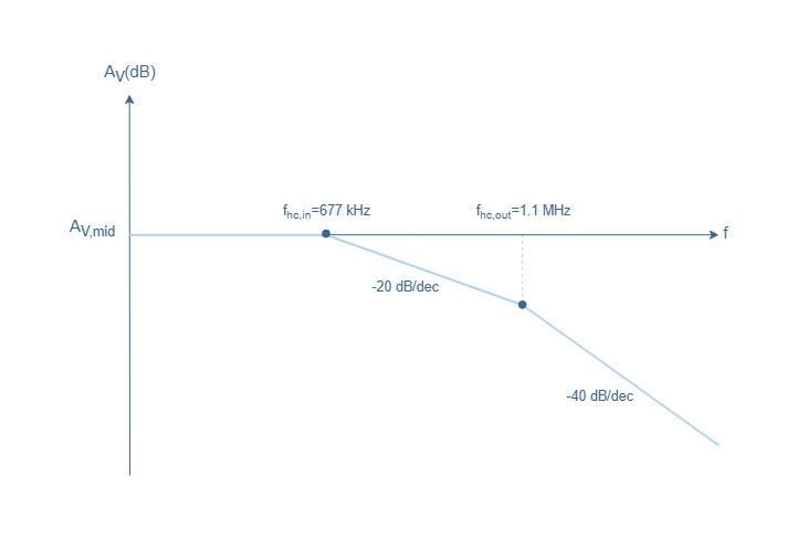
The total input capacitance of this circuit is CIN=CBE+Cin ; the total input resistance is RIN=RS//R1//R2//βre. The numerical application to our example gives AV,mid=(RC//RL)/re=108, CIN=575 pF and RIN=409 Ω. The high cutoff frequency of the input is therefore fhc,in=1/(2πRINCIN)=677 kHz.
From the output point of view, the high cutoff frequency is simply given by the filter (RC//RL)Cout with Cout=5.3 pF : fhc,out=1/(2π(RC//RL)Cout)=1.1 MHz.
The information given here is summarized in a Bode plot representing the high frequency response of the CEA in asymptotic representation :
fig 6 : High frequency response of the CEA
Conclusion
We have presented some key-concepts such as the decibel unit and the cutoff frequency in order to understand the idea of frequency response.
We have seen that many different types of capacitors influence both the low and high frequency response of amplifiers. Coupling and bypass capacitors indeed limit the low frequency response whereas the internal transistor capacitors limit the high frequency response.
In the two last sections, we show a step by step method to determine separately the low and high frequency response of a typical CEA configuration.
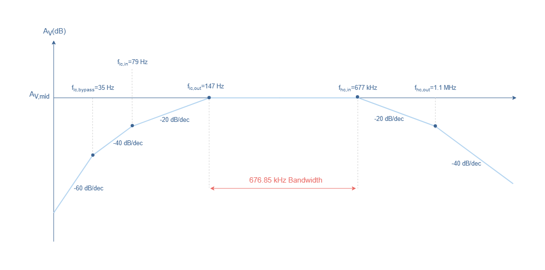
By merging the two Bode graphs obtained for the low and high frequency responses in Figure 4 and 6, we can now plot the overall frequency response of the CEA configuration :


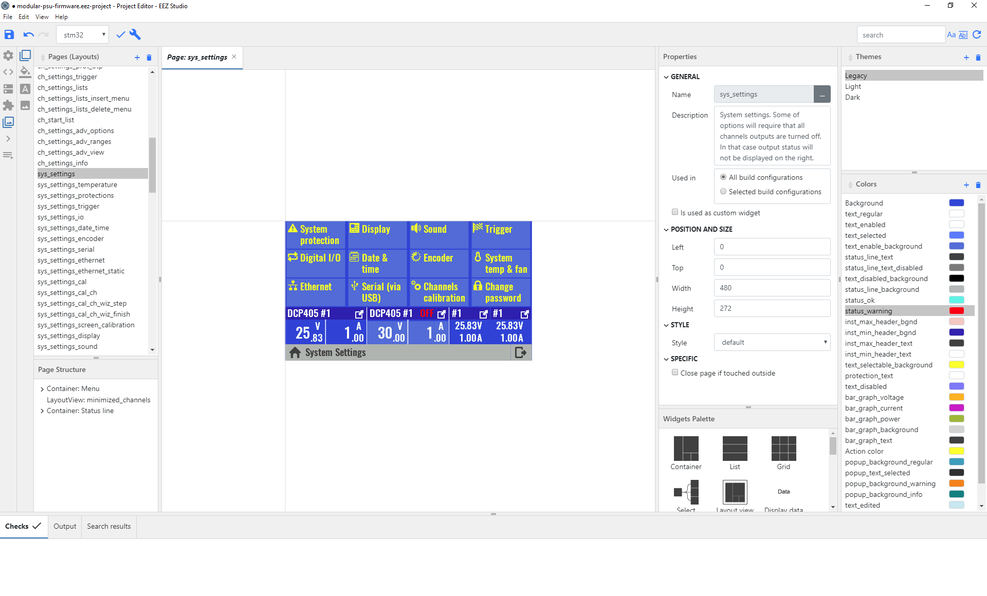 The other part of the EEZ Studio is the SCPI controller application that allows users access BB3 in an intuitive way using the simple text-based SCPI commands. Leveraging on the capacity of the SCPI controller, the EEZ Studio facilitates fast and accurate collection of data like; the instrument’s screen data, logged data, control of inputs and outputs, parameter settings. Each instrument has it’s own “session window” and all interaction are stored in SQL database for efficient searching, presentation and archiving.