Introduction
Despite their differences, we have seen in the previous tutorials about class A, class B and class AB amplifiers, that these three classes are linear or partially linear since they reproduce the shape of the signal during the amplification process. This is due to the fact that they use at least 50 % of the input signal, therefore a combination of two transistors in a push-pull configuration reproduces 100 % of the signal.
However, some amplifiers can be biased in such a way that they are not linear at all, this is the case of class C amplifiers that this tutorial focuses on. In the first section, the structure of such a configuration will be presented in detail since the output stage of class C amplifiers differs radically from the regular linear classes. Generalities will be also mentioned in this paragraph. In the following part, we will see how this type of amplifier works by focusing on the output/input characteristic. A third section will deal about the efficiency of the class C biasing architecture. Finally, a last section will show how this special amplifier can be used in modern electronics.
Presentation of the Class C amplification
As we have seen for class AB amplifiers, class C are not defined by a single operating point but rather an operating zone. This fact is illustrated in the Figure 1 below :
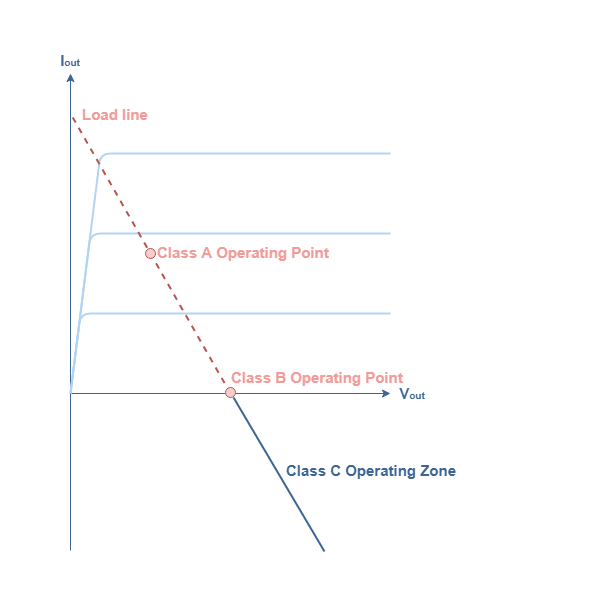
Since this operating zone extends beyond the class B operating point, which represents a 78.5 % efficiency and a 180° conduction angle, class C amplifiers are therefore characterized by a very high efficiency between 78.5 % and 100 % as we will detail more in the third section. Moreover, their conduction angle is very low, between 0° and 180°, which means that they conduct less than half of the signal. As we will see later on, it is precisely this fact that makes them non linear.
Class C amplifiers are mostly used for high frequency applications, they generate many harmonics that must be filtrated in order to faithfully reproduce the input signal. This filtration can be done for example with an RLC circuit as presented in the Figure 2 that represents the basic structure of class C amplifiers :
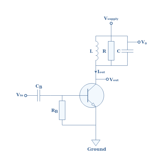
The aim of the RLC circuit, also known as “circuit stopper” is to eliminate the undesired frequencies and to only keep the fundamental frequency f1 of the input signal.
In practice, the load is coupled to the resonant circuit with a transformer as presented in Figure 3.
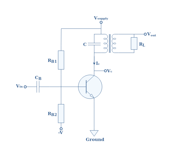
As already presented during the class A amplifier tutorial, this transformer-coupled configuration ensures that the load is isolated from the power supply and it is also used to realize an impedance matching. Moreover, the base is biased through a voltage divider network. In the following section, we will always refer to the Figure 3 circuit.
Class C functioning
The first goal of this section is to graphically represent the output current IC. In order to do that, we will use the transfer characteristic IC=f(VBE) where VBE is the base-emitter voltage difference.
We will admit that this transfer characteristic is approximately linear by segment such as shown in Figure 4. The first segment is between the origin and a threshold value VT and has a slope of zero. The second segment continues from VT and has a slope of gm (the transconductance).

As we can see from Figure 4, the output current can be described as “pulsed”. It can be characterized by two important parameters : the peak current ICM and the δ values that delimits the pulse signal. It is interesting to note that the conduction angle is equal to 2δ and represents the electrical angle in which the output current is not equal to zero.
If the output stage of the class C amplifiers does not have a circuit stopper but only a load, both the current and voltage are pulsed such as shown in Figure 4, this functioning mode is called the untuned mode. As explained more in detail in the last section, a proper choice of the value of the product L×C can lead to a functioning mode in tuned mode. In this mode, a particular frequency of the pulses is filtrated by the RLC circuit in order to regenerate the sine of the input signal, therefore performing a faithful amplification.
If we consider the input signal to be of the form Vin(t)=VI×sin(2πf1t), an important formula can be given in Equation 1 and links the maximal value of the output current ICM to the amplitude of the input signal VI :
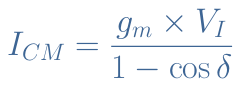
From this equation, we can understand that the conduction angle influences greatly the amplification process. The graph below represents the evolution of ICM for a conduction angle in the class C interval ]0° ; 180°[, that is to say for a δ value in the range ]0° ; 90°[.
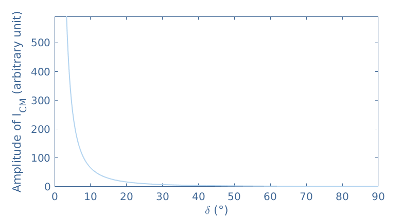
We can clearly note a fast decrease of the maximal value of the output current when the conduction angle increases. This graph gives an overview of the efficiency of the class C configuration : the smaller the conduction angle, the higher the output current.
In the tuned functioning mode, the output voltage can simply be written under the form Vout=Vsupply+k.Vsupply×sin(2πf1t+π). It is amplified by a factor k.Vsupply, phase shifted of π rad and presents an offset equal to Vsupply. Note that k is called the transformer coupling factor and is in the range [0;1]. This factor highlights the quality of the transformer used, for example a perfect transformer has a coupling factor of 1.
Efficiency of class C amplifiers
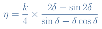
The method and steps to demonstrate the formula of efficiency η for class C amplifiers involves integral calculus and is not shown in this tutorial. The formula linking the efficiency to the parameters δ and k is given in the Equation 2 below :
It is interesting to visualize the dependency of the efficiency on both parameters in a graph given below :
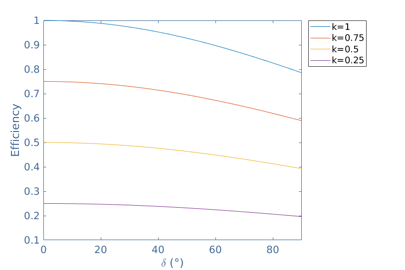
Best efficiencies are achieved with an ideal transformer where k=1. Moreover, we can highlight that if k=1 and the conduction angle is 180° (δ=90°), we are in a class B configuration and we recognize the maximal efficiency of 78.5 %.
A theoretical maximal efficiency of 100 % could be reached with k=1 and a zero conduction angle. However, for such values, the useful power delivered to the load is zero and therefore such efficiency cannot be achieved.
An application of class C amplifiers : the frequency multiplier
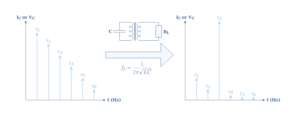
An interesting aspect of the circuit shown in Figure 3 is that the resonance circuit can be matched to the frequency of the input signal but as well to one of its harmonics. An harmonic is a multiple of the frequency f1 of the input signal of the form n×f1 with n an integer.
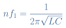
In order to realize this frequency match, the product L×C must satisfy the relation proposed in Equation 3 :
Since the collector current, as seen in Figure 4, is a pulse signal, its frequency spectrum already includes the fundamental frequency f1 and the following harmonics f2=2×f1, f3=3×f1, … If a frequency match is established for a certain harmonic, for example f3, this particular frequency will prevail over all the others. In this case, the voltage output is a sine signal of frequency f3 and amplitude RL×IC.
The Figure 7 below summarizes this function of frequency multiplier :
Conclusion
Class C amplifiers present higher efficiencies than class A, B or AB. However, their conduction angle is very low between 0° and 180°, meaning that they conduct only a fraction of the signal. This fact leads to a poor linearity of the amplifier, both voltage and current outputs are very distorted because they present a high number of harmonics.
In order to overcome this problem, the output stage of a class C amplifier must be wired to what is commonly known as a stopper circuit. This filter consists of a parallel RLC arrangement that selects only the desired harmonic to be amplified, if a faithful amplification is needed, the RLC circuit is matched to the fundamental frequency of the input signal. The inductance is generally replaced by a transformer in order to properly isolate the load from the supply and to match the impedance.
We have seen in the second section that two functioning modes can appear :
- If the stopper circuit does not match any particular harmonic of the initial signal, the output signals are pulsed : this is the untuned mode.
- If the stopper circuit is tuned to the fundamental frequency or any harmonic, the class C amplifier becomes linear and the output signals are sine waves : this is the tuned mode.
Later on, the efficiency of class C amplifiers has been discussed and we concluded that high efficiencies are more likely to happen for ideal transformers with coupling factors that tend to 1 and low conducting angles that tend to 0. However, no useful power can be delivered to the load with such a conducting angle. In practice, a good compromise is to set the angle to 120° to obtain both a good efficiency and a high enough fraction of the input signal conducted.
Finally, we have seen that class C amplifiers can be tuned to any higher harmonic of the input signal in order to realize a frequency multiplier circuit. For this reason, class C amplifiers are appropriate in the design of frequency synthesizers and telecommunication applications.