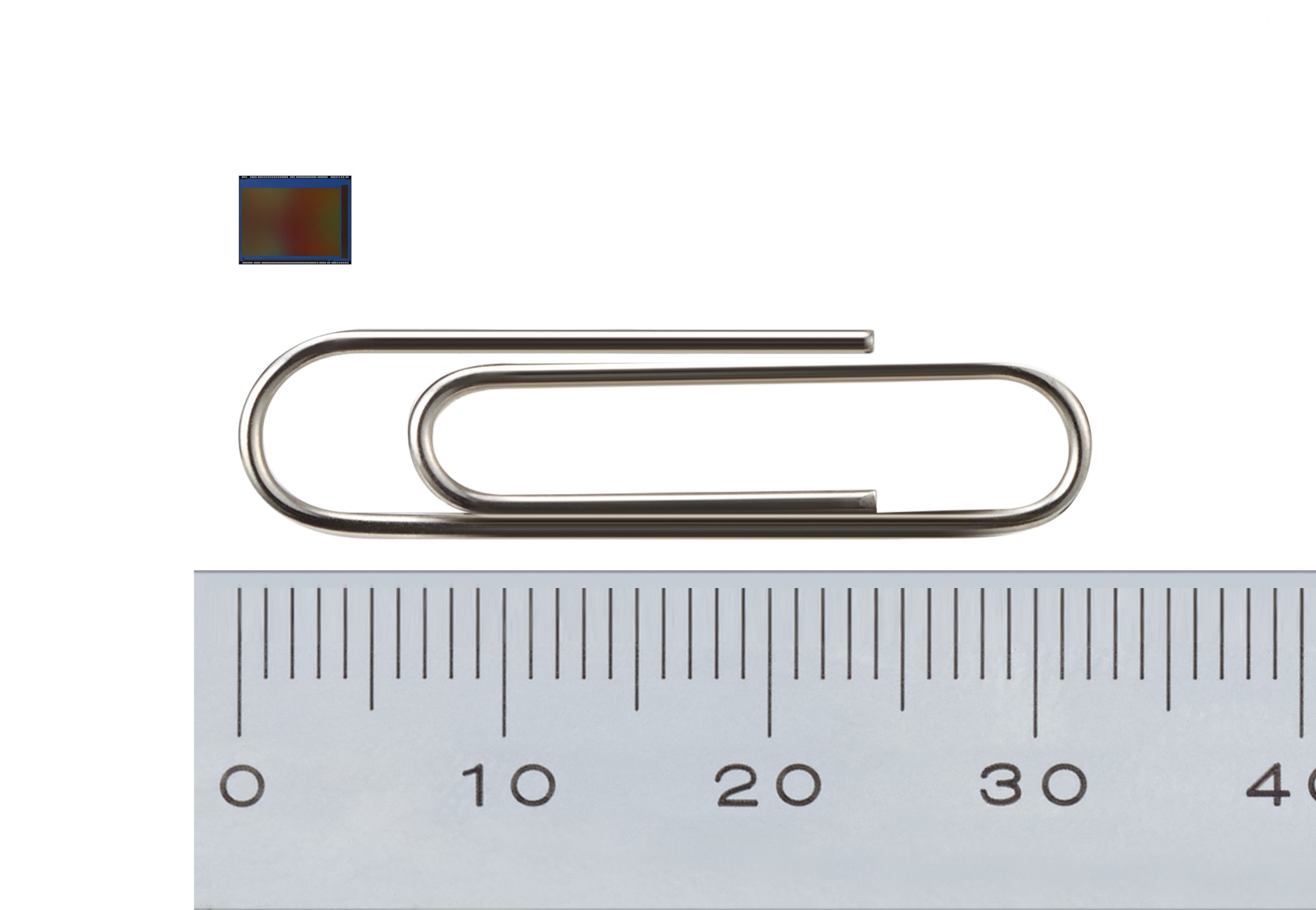
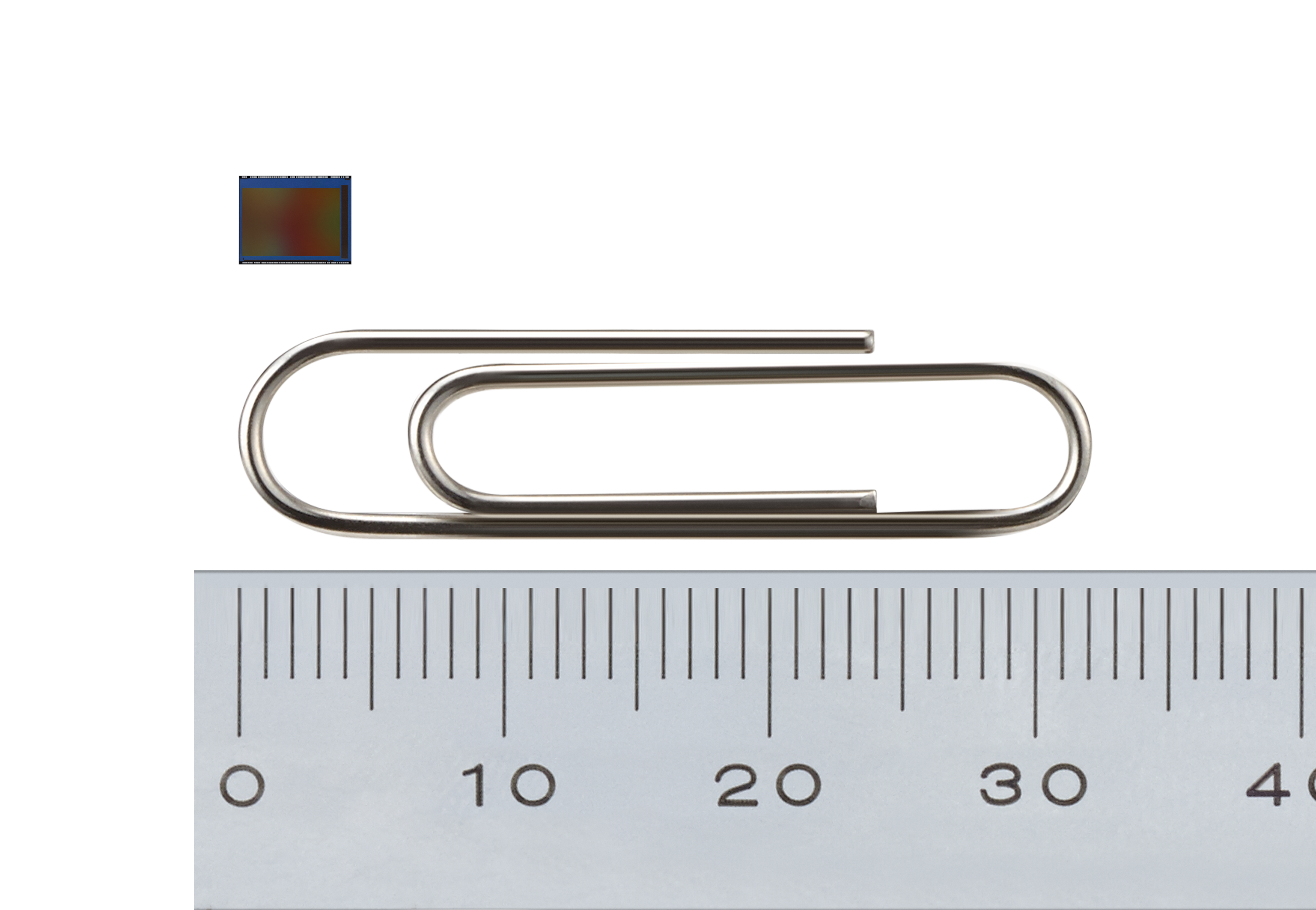
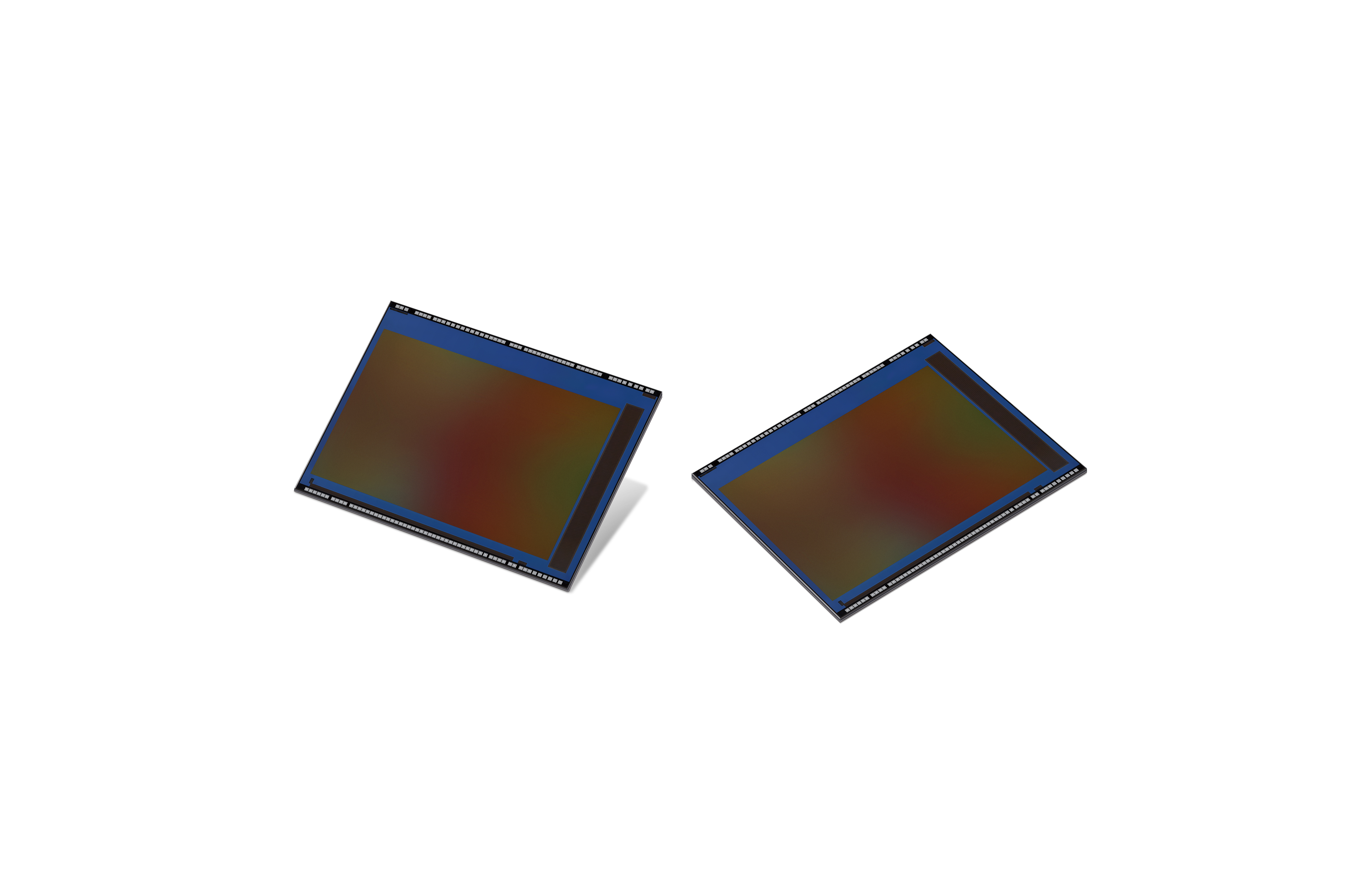
Samsung ISOCELL Slim GH1 offers 43.7 megapixels in an extremely compact package, ideal for slim full-display smartphones
Samsung Electronics, a world leader in advanced semiconductor technology, today introduced the industry’s first 0.7-micrometer (μm)-pixel image sensor, the 43.7-megapixel (Mp) Samsung ISOCELL Slim GH1. Thanks to advanced ISOELL Plus technology, the new ultra-high-resolution GH1 image sensor embraces 43.7-million 0.7μm-sized pixels in a super-small package, providing the optimum solution for slim full-display devices.
“Samsung has been stepping up in pixel technology innovation from the industry’s first 1.0μm-pixel image sensor, to most recently, 0.8μm ultra-high-resolution sensors at 64Mp and 108Mp,” said Yongin Park, executive vice president of the sensor business at Samsung Electronics. “We are pleased to deliver yet another breakthrough with the industry’s first 0.7μm pixel image sensor, the ISOCELL Slim GH1 that will enable sleeker and more streamlined designs as well as excellent imaging experiences in tomorrow’s smartphones.”
The ISOCELL Slim GH1 is the industry’s first mobile image sensor to adopt the smallest pixel size in the industry at 0.7μm. By utilizing ISOCELL Plus, Samsung’s latest pixel isolation technology that minimizes color cross-talk and optical loss, the tiny 0.7μm pixels are able to absorb sufficient light information to produce bright and vivid photographs. In low-light environments, the GH1 makes use of pixel-merging Tetracell technology that enables higher light sensitivity equivalent to that of a 1.4μm-pixel image sensor.
For video recording at 4K (3,840×2,160) resolutions, the ISOCELL Slim GH1, with a high resolution of 7,968×5,480, is able to take 4K videos with minimum loss in field of view (FoV), while most high-resolution image sensors crop or scale down full image resolutions that result in a reduced FoV. Using Tetracell technology, the GH1 is converted down to 3,984×2,740, a resolution that snugly covers the 4K (3,840×2,160) resolution, allowing users to capture more detailed backgrounds when recording high-resolution videos or selfies at 60T frames per second (fps).
For sharper photographs and video, the GH1 supports a gyro-based electronic image stabilization (EIS) and a high-performing phase detection auto-focus technology, Super PD, allowing fast and accurate autofocus. In addition, the real-time high dynamic range (HDR) feature delivers more balanced exposure and richer color even in mixed-light environments.
The Samsung ISOCELL Slim GH1 is expected to be in mass production by the end of this year.
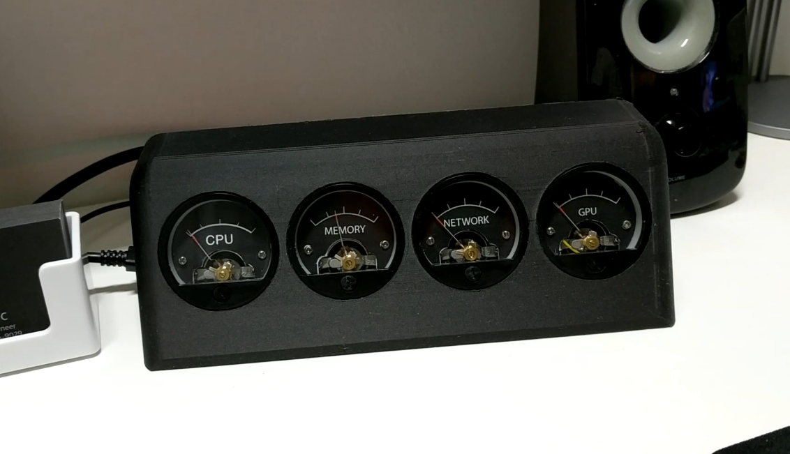
Sasa Karanovic build an analog monitoring system that is able to show your computer’s resources on 4x beautiful dials. He writes:
As I mentioned, I’ve been playing around with this idea for a while and by looking at some of my notes, the idea of having a physical resource monitor for my PC dates years and years back (see images at the end for some early on prototypes that I was able to dig up).
Since I unfortunately can’t publicly write about the awesome projects I get hired to work on, I try to write about projects that I do in my own spare time and present them to my readers as DIY projects/guides. I take these very seriously and out of the respect to my readers who patiently wait for my next project post, thank you all for that very much, I try to keep the projects posts very detailed and provide every piece of information or files that you might need to build one yourself.
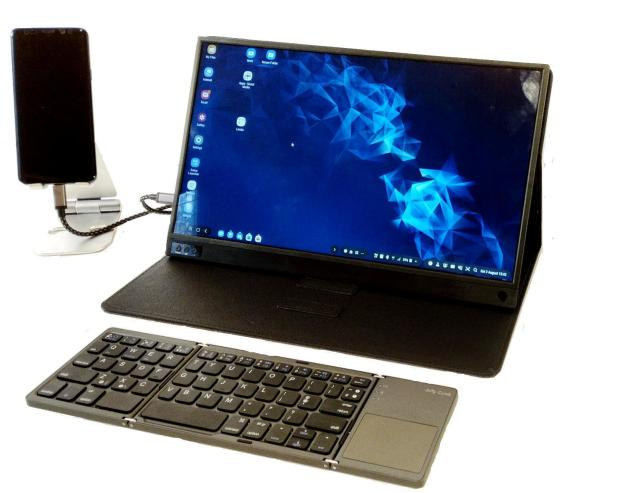
Laptop Docks for smartphones are becoming quite the real deal. For those who are not yet familiar with them, the docks serve as hosts for turning smartphones into laptops. As their popularity grows, the market is awash with several types of laptop docks with some top performers like the NexDock2 and AFAICR, both of which come with a full laptop body, non-touch display and keyboard. However, “Losing the wires” recently announced they will be offering something slightly different from the popular others in the market with their recently released Sm@rtDock 15 Touch laptop dock.
The Sm@rtDock 15 Touch was designed to convert phones like the Samsung DeX into 2-in-1 hybrid laptops. The Sm@rtDock 15 Touch comes with a touch screen display and a detachable keyboard, given users the opportunity to use just the touch screen display in a model similar to that of a tablet, or as a laptop with the keyboard connected. This is one of the major ways through which the Sm@rtDock 15 Touch distinguishes itself from exiting competition as it offers users more options around flexibility and use-case/scenarios.
The Sm@rtDock 15 Touch was designed with the current generation of smartphones in mind as such it possesses a 1 USB-C port through which the Smartphone is connected and a micro-USB to which it is expected that peripherals will be connected. The Sm@rtDock 15 Touch was purely designed as a product for the UK market as such, most of the peripherals like keyboard, etc., have UK Configurations but on a retail/distributor level, the company should be able to provide keyboard and power supply for other markets/language.
Sm@rtDock 15 Touch kit includes the following items and features:
15.6″ LCD display
Full HD/1080p resolution (1920 x 1080 pixels) with 10 point capacitive touch
USB – 1x USB-C port to smartphone, 1 x micro-USB port for peripherals, 1x USB- C charge port
Video Output – Mini-HDMI in for use as a secondary display for another device
Battery – Up to 4 or up to 7 hours life (model specific)
Dimensions – 356 x 224 x 9mm
Weight – 900g (without case)
UK Bluetooth keyboard with trackpad
UK charger, USB-C smartphone cable, and folding case
Cables
Hard carry case/stand
According to “losing the wires” website, the Sm@rtDock 15 Touch is said to work with Samsung S8, S9, S10, Note 8, Note 9 and Note 10 devices using DeX, Huawei/Honor devices using Easy Projection, as well as other devices supporting DisplayPort Alternate Mode over USB-C.
Intro Video
“Losing the wires” did not put the price of the Sm@rtDock 15 Touch on their website, but the best guess is it will still be around the range of similar devices in the market. More information on the system can be found on the product page.
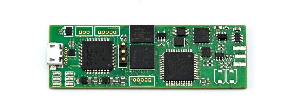
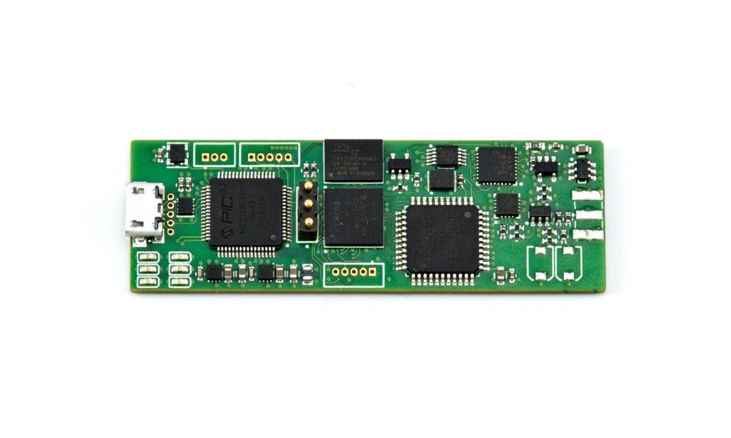
After the release of his PIC32MZ EF based 20Msps oscilloscope with an integrated 1-inch by 1-inch OLED screen for readouts, Electrical Engineer, Mark Omo has again unveiled his new design, the self-contained 60MHz 250Msps Probe Scope oscilloscope with the probe in cable form factor.
The Probe-scope oscilloscope which runs at 250Msps and has a bandwidth of 60MHz was designed to bridge the large market gap between existing low-performance low-cost open-source oscilloscopes and expensive professional closed-source oscilloscopes.
The new innovation to the world of oscilloscopes is in three sectional parts: the programmable gain amplifier, acquisition hardware and, the input /divider buffer. The open-source PIC32MZ-based oscilloscope has its acquisition hardware built in it and plugs directly into a PC via USB. The signal is passed from the input /divider buffer through a fixed 30X divider and buffered through an op-amp to a 15V range. It is later piped over a differential op-amp and added to an offset signal produced by a DAC before passing along to the gain settings of the PGA. The signal is attenuated by an ADRF6518 PGA with a little bit of anti-aliasing before it is sent to the analog devices’ AD9481 ADC to be conditioned and further handled off to a MachXO2-4000 FGPA to be stored into a 128Mb HyperRAM, set for one trigger. From the HyperRAM, a PIC32MZ EF microcontroller connected to the FGPA reads it off and shoots it over USB to a connected PC.
Intro Video
According to Omo,
“The Probe-Scope grows as you grow, giving you as many channels as you have USB ports, the probe scope is almost infinitely expandable to tens (or more!) of channels”. He also stated that the design us ready to be taken to market, stating that, ” the hardware design Is complete; our final PCBs were produced and assembled by PCBWay and functioned as expected right out of the box”. Omo and team are planning on using the same design for volume manufacturing, with only minor changes to the connectors.
As a competitor against Rigol’s DS1054Z digital oscilloscope sold for $350, Omo hopes to keep the cost of the Probe-scope at $100. Meanwhile, a detailed walkthrough of his Probe-Scope project has been uploaded on Hackaday for those who might be interested in building theirs.
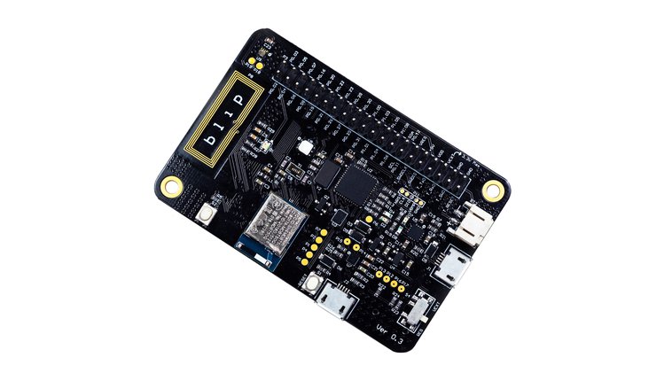
Blip is a development board for Bluetooth Low Energy (BLE) and 802.15.4-based wireless applications, built around the Nordic Semiconductor nRF52840 SoC. It is able to help you easily start your next IoT Development using BLE technology.
Blip has a Black Magic Probe compatible programmer and debugger built in, along with a temperature/humidity sensor, ambient light intensity sensor, and a three-axis accelerometer. It can be used to prototype very low power devices. It also has provisions for a microSD card slot, which makes it a complete and versatile development board.
Blip supports Nordic Semiconductor nRF5 SDK, Zephyr RTOS, Arduino and CircuitPython, so users can easily find resources to interface it with pretty much any hardware. There’s even an Adroid/iOS App and a Bluetooth web interface.
Features
Controller: Raytac MDBT50Q-1M module based on Nordic Semiconductor’s nRF52840 module with FCC/TELEC/CE certification
Visualizations are an important part of a music player. They provide the user with something to feast their eyes on especially when the music has no video. For today’s tutorial, we will build a visualization device, capable of providing a visual representation for any kind of music fed into it.
The goal of this project is to get smooth, appealing music visualization on the ATTiny85, optimizing around its limited speed and resources (RAM and program memory). It’s an ongoing project being developed by GitHub user Colonel Watch, which is mostly complete but it’s otherwise fully functional and ready to be flashed.
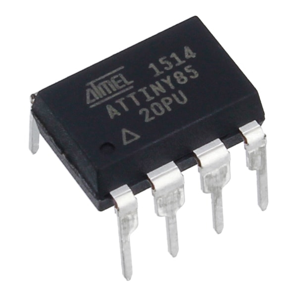
At the heart of today’s project is the Attiny85 which is an 8-bit, low power AVR microcontroller based on RISC CPU architecture and comes as an 8-pin PDIP interface. It is a very small microcontroller with impressive inbuilt functions that helps it perform wonderfully well and fits into the needs of users who want a very tiny DIP microcontroller.
Attiny85 Audio Spectrum Analyzer on OLED display – [Link]
Visualizations are an important part of a music player. They provide the user with something to feast their eyes on especially when the music has no video. For today’s tutorial, we will build a visualization device, capable of providing a visual representation for any kind of music fed into it.
Audio Visualizer
The goal of this project is to get smooth, appealing music visualization on the ATTiny85, optimizing around its limited speed and resources (RAM and program memory). It’s an ongoing project being developed by GitHub user Colonel Watch, which is mostly complete but it’s otherwise fully functional and ready to be flashed.
ATtiny85
At the heart of today’s project is the Attiny85 which is an 8-bit, low power AVR microcontroller based on RISC CPU architecture and comes as an 8-pin PDIP interface. It is a very small microcontroller with impressive inbuilt functions that helps it perform wonderfully well and fits into the needs of users who want a very tiny DIP microcontroller.
Some of the features of the attiny85 include;
Flash type Program Memory
8Kb flash memory
20 MIPS/DMIPS CPU Speed
512 bytes of SRAM
512 bytes of EEPROM
Supports SPI(1) and I2C(1) communication protocols
5 PWM pins
8-bit Timers (2)
1.8v – 5.5V operating voltage
For this project, the Attiny85 is charged with obtaining the signal through the analog frontend created along it’s ADC, then compute the signal and display the output.
Required Components
The following components are required to build this project;
ATTiny85
SSD1306 OLED Module
3-Pole Audio Jack (1, 2 for pass-through)
2N3904 or other NPN transistor
0.1uF Capacitor
Potentiometer (any value above 10k)
200 Ohm Resistor (2)
820 Ohm Resistor
100k Ohm Resistor
External 5V Power Supply
These components can all be bought from any electronics store, online or offline.
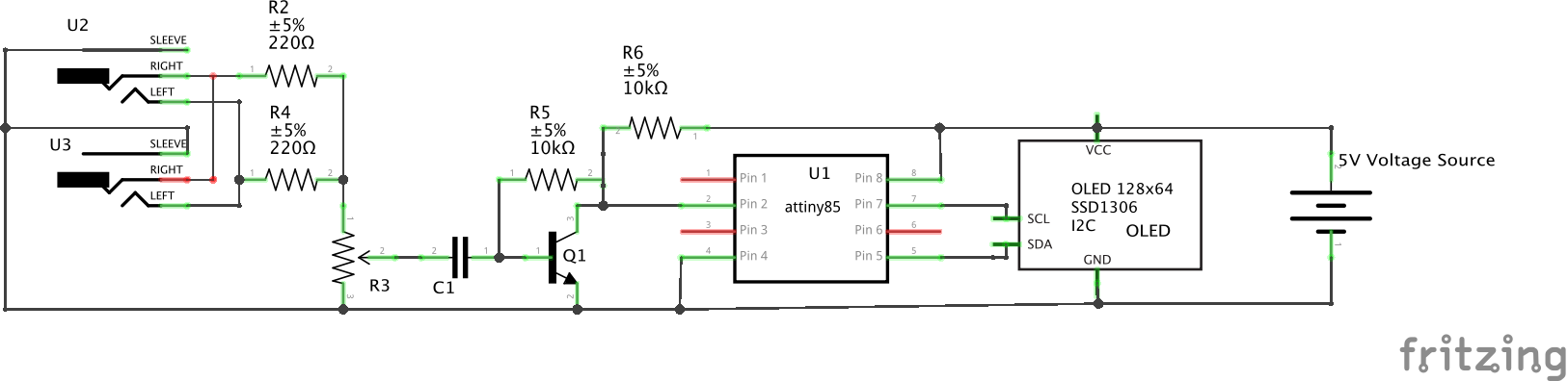
Schematics
The schematics for today’s project is not as straightforward as often as we have to interconnect a couple of resistors and other passives.
Connect the components as shown in the schematics below.
Schematics
The idea behind the schematics is to allow us to receive audio inputs from the audio jacks, process the sound signals and feed into an analog pin on the Attiny85, which then processes the signal and generates the data which is communicated to the OLED for display via I2C.
Since the other connections are a bit difficult to describe on a pin to pin level, we will only look at that of the OLED and the Attiny. The pin to pin connection between the Attiny85 and the OLED is described in the pin map below.
OLED – Attiny85
SDA - Pin 5
SCL - Pin 7
VCC - 5V
GND - GND
With this done, we are now ready to write the code for the project. Go over the connections once again to ensure everything is as it should be.
Code
As mentioned earlier, the goal for this project is to display smooth and appealing sound visualization. To work around the limited resources in terms of the RAM size of the Attiny85 and the poor quality of the OLED display, we will use two libraries; the fix_fft, the nano_engine library, and the ssd1306 libraries. The fix_fft is an AVR implementation of a faster 8-bit integer-based FFT for signal processing while the SSD1306 library will help reduce the size and complexity of the code we need to write to display data on the OLED. The nano_engine library will be used to draw sector by sector lines on the OLED because the attiny85 can’t hold a full buffer.
As usual, I will be doing a breakdown/quick explanation of the code to explain its technical parts.
We start the code by including the libraries that we will use.
// Copyright [2019] [colonelwatch]

#include "fix_fft.h"                  // 8-bit FFT library modified for Arduino
#include "ssd1306.h"                  // library for OLED
#include "nano_engine.h"              // library for nanoengine (which draws sector-by-sector on OLED because the ATtiny85 can't hold a full buffer)
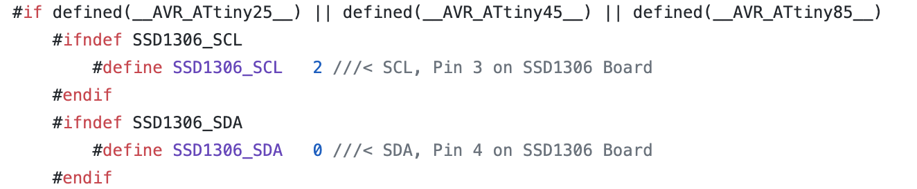
Next, we need to configure the SSD1306 library to suit our Attiny85 by setting the SDA and SCL pins to 0 and 2 respectively. To do this, we need to take a detour and visit the SSD1306 library to make the adjustments. Go to the SSD1306 library and open the ssd1306_12c.conf.h file. You can follow this path (libraries\ssd1306\src\intf\i2c\ssd1306_i2c_conf.h ) to get to it. Open the file and assign the SDA pin to 0 and the SCL pin to 2 like shown in the image below.
Edit Library
Note: don’t forget to undo this change after uploading the code so you can use the library in the future.
With that done, we create some of the variables that we will use to store various data in the code.
// These are user-adjustable
//#define LOG_OUTPUT              // Uncomment to enable logarithmic output (exchanges absolute resoluton for more readable output; may require different below params)
#define SAMPLING_FREQUENCY 15000  // Sampling frequency (Actual max measured frequency captured is half)
#define TIME_FACTOR 3             // Smoothing factor (lower is more dynamic, higher is smoother) ranging from 1 to 10+
#define SCALE_FACTOR 12           // Direct scaling factor (raise for higher bars, lower for shorter bars)

#ifdef LOG_OUTPUT
const float log_scale = 64./log(64./SCALE_FACTOR + 1.);                              // Attempts to create an equivalent to SCALE_FACTOR for log function
#endif
const float coeff = 1./TIME_FACTOR;                                                  // Time smoothing coefficients (used to factor in previous data)
const float anti_coeff = (TIME_FACTOR-1.)/TIME_FACTOR;
const unsigned int sampling_period_us = round(1000000 * (2.0 / SAMPLING_FREQUENCY)); // Sampling period (doubled to account for overclock)

int8_t data[64], buff[32];                                     // used to store FFT input/output and past data
unsigned long microseconds;                                    // used for timekeeping
int summ, avg;
The above variables are important and can vary as they are used in setting the size of the bars, frequency of display, resolution and other related parameters.
Next, we create an instance of the nano engine library and then move to the void setup function.
NanoEngine<TILE_32x32_MONO> engine;
The void setup() function contains a vital piece of actions. We start by overclocking the CPU to around 30MHz to increase the sampling rate and overall processor speed in a way to improve the result and fluidity on the display.
OSCCAL = 240; // Overclocks the MCU to around 30 MHz, set lower if this causes instability, raise if you can/want
Next, we set the value of the ADC Clock to align with the sample rate we have in mind, we then proceed to initialize the SSD1306 display and start the nano engine.
ADCSRA &= ~(bit (ADPS0) | bit (ADPS1) | bit (ADPS2));       // clear ADC prescaler bits
  ADCSRA |= bit (ADPS2);                                      // sets ADC clock in excess of 10kHz
  ADCSRA |= bit (ADPS0);

  ssd1306_128x64_i2c_init();                                  // initializes OLED
  ssd1306_clearScreen();                                      // clears OLED

  engine.begin();                                             // inititalizes nanoengine
};
With that done, we move to the void loop function.
We start this function by reading the analog pin to which the processed audio signal is connected on the attiny85.
summ = 0;
  for (int i = 0; i < 64; i++) {
    microseconds = micros();

    data[i] = ((analogRead(A3)) >> 2) - 128;                        // Fitting analogRead data (range:0 - 1023) to int8_t array (range:-128 - 127)
    summ += data[i];
    while (micros() < (microseconds + sampling_period_us)) {        // Timing out uC ADC to fulfill sampling frequency requirement
    }
  }
The DC component of the signal is then eliminated to ensure the data is usable for the FFT analysis.
avg = summ/64;
  for (int i = 0; i < 64; i++){
    data[i] -= avg;
  }
With this done, we then call the FFT function to perform the Fast Fourier transform on the signal.
fix_fftr(data, 6, 0); // Performing real FFT
The predefined user-determined scaling factors are then used to fine tune and smoothing the signal to generate the output signal values for display.
// Time smoothing by user-determined factor and user-determined scaling
  for(int count = 0; count < 32; count++){
  if(data[count] < 0) data[count] = 0;                                          // Eliminating negative output of fix_fftr
  #ifdef LOG_OUTPUT
  else data[count] = log_scale*log((float)(data[count]+1));                     // Logarithmic function equivalent to SCALING_FACTOR*log2(x+1)
  #else
  else data[count] *= SCALE_FACTOR;                                             // Linear scaling up according to SCALE_FACTOR
  #endif
  data[count] = (float)buff[count] * anti_coeff + (float)data[count] * coeff;   // Smoothing by factoring in past data
  buff[count] = data[count];                                                    // Storing current output as next frame's past data
  if(data[count] > 63) data[count] = 63;                                        // Capping output at screen height
  }
Since the attiny85 cant hold a full buffer, the data to be displayed is first parsed by the nano_engine object Engine that we created earlier. The nano engine then draws a line by line representation of the signal on the OLED Display. The loop continues and as soon as new signal/sound arrives, it is processed and added on the display, creating the soothing visualization desired.
engine.canvas.clear();                                          // Clear canvas as previous data
  for(int i = 0; i < 8; i++){
    engine.canvas.drawVLine(i*4,31-(data[i]+1),31);          // Draw to canvas data for lower-leftest sector (FFT bins 0 - 7, lower half)
  }
  engine.canvas.blt(0,32);                                        // Outputs canvas to OLED with an offset (x pixels, y pixels)
  engine.canvas.clear();
  for(int i = 0; i < 8; i++){
    if(data[i] > 31) engine.canvas.drawVLine(i*4,31-(data[i]-31),31);     // Draw to canvas data for upper-leftest sector (FFT bins 0 - 7, upper half)
  }
  engine.canvas.blt(0,0);
  engine.canvas.clear();
  for(int i = 8; i < 16; i++){
    engine.canvas.drawVLine((i-8)*4,31-(data[i]+1),31);      // FFT bins 8 - 15, lower half
  }
  engine.canvas.blt(32,32);
  engine.canvas.clear();
  for(int i = 8; i < 16; i++){
    if(data[i] > 31) engine.canvas.drawVLine((i-8)*4,31-(data[i]-31),31);   // FFT bins 9 - 15, upper half
  }
  engine.canvas.blt(32,0);
  engine.canvas.clear();
  for(int i = 16; i < 24; i++){
    engine.canvas.drawVLine((i-16)*4,31-(data[i]+1),31);     // FFT bins 16 - 23, lower half
  }
  engine.canvas.blt(64,32);
  engine.canvas.clear();
  for(int i = 16; i < 24; i++){
    if(data[i] > 31) engine.canvas.drawVLine((i-16)*4,31-(data[i]-31),31);  // FFT bins 16 - 23, upper half
  }
  engine.canvas.blt(64,0);
  engine.canvas.clear();
  for(int i = 24; i < 32; i++){
    engine.canvas.drawVLine((i-24)*4,31-(data[i]+1),31);     // FFT bins 24 - 31, lower half
  }
  engine.canvas.blt(96,32);
  engine.canvas.clear();
  for(int i = 24; i < 32; i++){
    if(data[i] > 31) engine.canvas.drawVLine((i-24)*4,31-(data[i]-31),31);  // FFT bins 24 - 31, upper half
  }
  engine.canvas.blt(96,0);
The complete code for the project can be found below and is also attached under the download section along with other project files.
// Copyright [2019] [colonelwatch]

#include "fix_fft.h"                  // 8-bit FFT library modified for Arduino
#include "ssd1306.h"                  // library for OLED
#include "nano_engine.h"              // library for nanoengine (which draws sector-by-sector on OLED because the ATtiny85 can't hold a full buffer)

// To get this program to operate, the SDA and SCL pins must be reassigned to 0 and 2 respectively in the library header file
// The file is located in libraries\ssd1306\src\intf\i2c\ssd1306_i2c_conf.h
// Make sure to undo this if the library will be used again in the future

// These are user-adjustable
//#define LOG_OUTPUT              // Uncomment to enable logarithmic output (exchanges absolute resoluton for more readable output; may require different below params)
#define SAMPLING_FREQUENCY 15000  // Sampling frequency (Actual max measured frequency captured is half)
#define TIME_FACTOR 3             // Smoothing factor (lower is more dynamic, higher is smoother) ranging from 1 to 10+
#define SCALE_FACTOR 12           // Direct scaling factor (raise for higher bars, lower for shorter bars)

#ifdef LOG_OUTPUT
const float log_scale = 64./log(64./SCALE_FACTOR + 1.);                              // Attempts to create an equivalent to SCALE_FACTOR for log function
#endif
const float coeff = 1./TIME_FACTOR;                                                  // Time smoothing coefficients (used to factor in previous data)
const float anti_coeff = (TIME_FACTOR-1.)/TIME_FACTOR;
const unsigned int sampling_period_us = round(1000000 * (2.0 / SAMPLING_FREQUENCY)); // Sampling period (doubled to account for overclock)

int8_t data[64], buff[32];                                     // used to store FFT input/output and past data
unsigned long microseconds;                                    // used for timekeeping
int summ, avg;                                                 // used for DC bias elimination

NanoEngine<TILE_32x32_MONO> engine;                            // declares nanoengine

void setup()
{
  OSCCAL = 240; // Overclocks the MCU to around 30 MHz, set lower if this causes instability, raise if you can/want

  ADCSRA &= ~(bit (ADPS0) | bit (ADPS1) | bit (ADPS2));       // clear ADC prescaler bits
  ADCSRA |= bit (ADPS2);                                      // sets ADC clock in excess of 10kHz
  ADCSRA |= bit (ADPS0);

  ssd1306_128x64_i2c_init();                                  // initializes OLED
  ssd1306_clearScreen();                                      // clears OLED

  engine.begin();                                             // inititalizes nanoengine
};

void loop()
{
  summ = 0;
  for (int i = 0; i < 64; i++) {
    microseconds = micros();

    data[i] = ((analogRead(A3)) >> 2) - 128;                        // Fitting analogRead data (range:0 - 1023) to int8_t array (range:-128 - 127)
    summ += data[i];
    while (micros() < (microseconds + sampling_period_us)) {        // Timing out uC ADC to fulfill sampling frequency requirement
    }
  }

  // Eliminating remaining DC component (produces usable data in FFT bin #0, which is usually swamped by DC bias)
  avg = summ/64;
  for (int i = 0; i < 64; i++){
    data[i] -= avg;
  }

  fix_fftr(data, 6, 0);                             // Performing real FFT

  // Time smoothing by user-determined factor and user-determined scaling
  for(int count = 0; count < 32; count++){
  if(data[count] < 0) data[count] = 0;                                          // Eliminating negative output of fix_fftr
  #ifdef LOG_OUTPUT
  else data[count] = log_scale*log((float)(data[count]+1));                     // Logarithmic function equivalent to SCALING_FACTOR*log2(x+1)
  #else
  else data[count] *= SCALE_FACTOR;                                             // Linear scaling up according to SCALE_FACTOR
  #endif
  data[count] = (float)buff[count] * anti_coeff + (float)data[count] * coeff;   // Smoothing by factoring in past data
  buff[count] = data[count];                                                    // Storing current output as next frame's past data
  if(data[count] > 63) data[count] = 63;                                        // Capping output at screen height
  }

  // Output to SSD1306 using nanoengine canvas from library
  engine.refresh();                                               // Mark entire screen to be refreshed
  engine.canvas.clear();                                          // Clear canvas as previous data
  for(int i = 0; i < 8; i++){
    engine.canvas.drawVLine(i*4,31-(data[i]+1),31);          // Draw to canvas data for lower-leftest sector (FFT bins 0 - 7, lower half)
  }
  engine.canvas.blt(0,32);                                        // Outputs canvas to OLED with an offset (x pixels, y pixels)
  engine.canvas.clear();
  for(int i = 0; i < 8; i++){
    if(data[i] > 31) engine.canvas.drawVLine(i*4,31-(data[i]-31),31);     // Draw to canvas data for upper-leftest sector (FFT bins 0 - 7, upper half)
  }
  engine.canvas.blt(0,0);
  engine.canvas.clear();
  for(int i = 8; i < 16; i++){
    engine.canvas.drawVLine((i-8)*4,31-(data[i]+1),31);      // FFT bins 8 - 15, lower half
  }
  engine.canvas.blt(32,32);
  engine.canvas.clear();
  for(int i = 8; i < 16; i++){
    if(data[i] > 31) engine.canvas.drawVLine((i-8)*4,31-(data[i]-31),31);   // FFT bins 9 - 15, upper half
  }
  engine.canvas.blt(32,0);
  engine.canvas.clear();
  for(int i = 16; i < 24; i++){
    engine.canvas.drawVLine((i-16)*4,31-(data[i]+1),31);     // FFT bins 16 - 23, lower half
  }
  engine.canvas.blt(64,32);
  engine.canvas.clear();
  for(int i = 16; i < 24; i++){
    if(data[i] > 31) engine.canvas.drawVLine((i-16)*4,31-(data[i]-31),31);  // FFT bins 16 - 23, upper half
  }
  engine.canvas.blt(64,0);
  engine.canvas.clear();
  for(int i = 24; i < 32; i++){
    engine.canvas.drawVLine((i-24)*4,31-(data[i]+1),31);     // FFT bins 24 - 31, lower half
  }
  engine.canvas.blt(96,32);
  engine.canvas.clear();
  for(int i = 24; i < 32; i++){
    if(data[i] > 31) engine.canvas.drawVLine((i-24)*4,31-(data[i]-31),31);  // FFT bins 24 - 31, upper half
  }
  engine.canvas.blt(96,0);
}
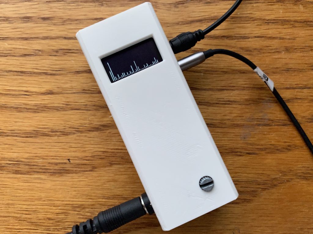
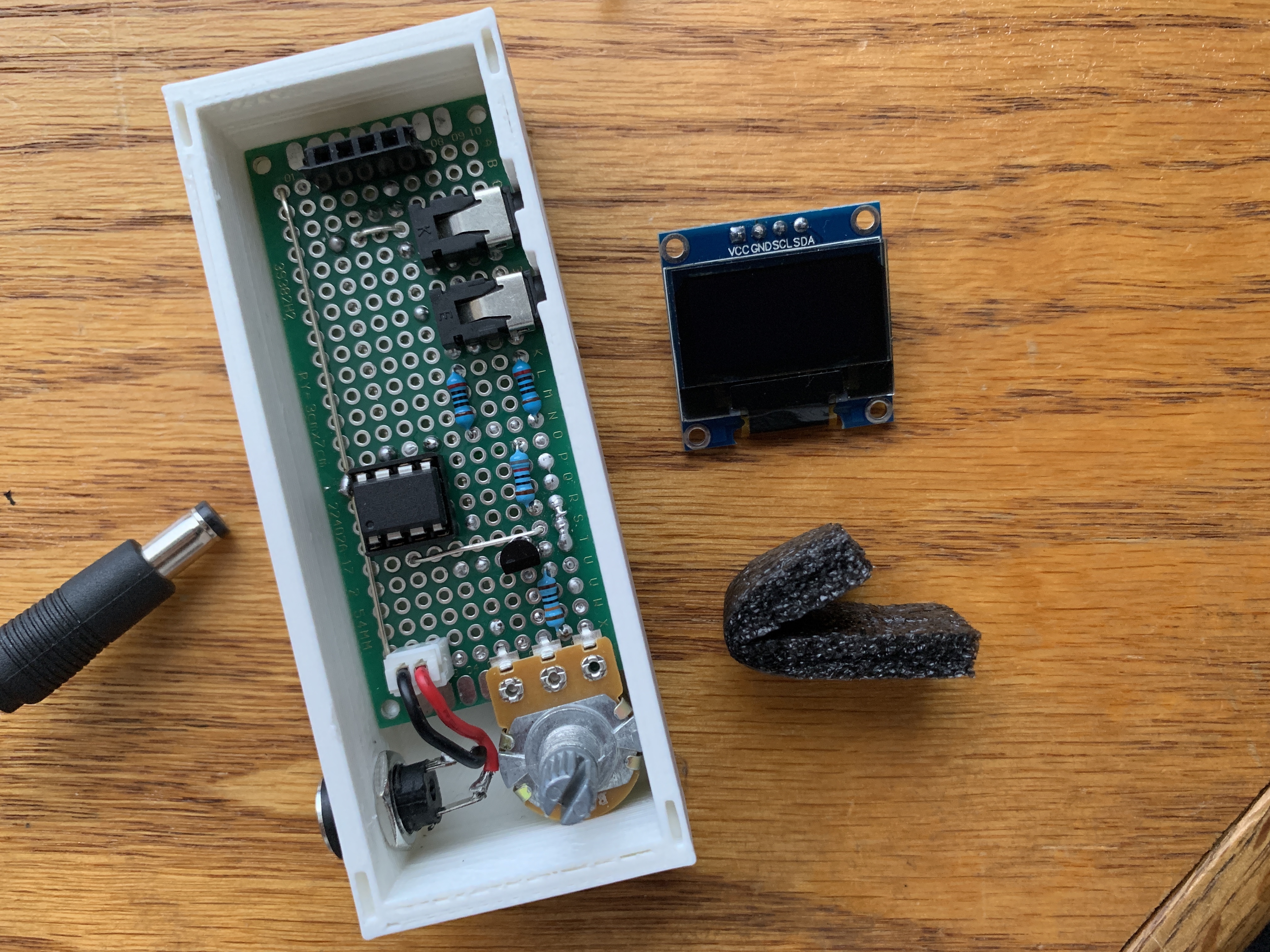
Enclosure Design
To make the project as cool as imagined, it seemed a good idea to design and 3D print an enclosure for it. The created enclosure was designed in such a way that accommodated the screen and the audio jacks in a nice way.
Fitting the project in the enclosure
The STL files for the enclosure are also included in the download files.
Demo
Go over the connections once again and ensure you have all the library for the code installed and that the sketch verifies. With all these checked, Upload the code to your attiny85 following the procedure to program the attiny85 described here.
With the Attiny85 programmed, insert it back into the breadboard and power the system. Connect a sound cable to the jacks, and you should see visualization come up as shown below after a few seconds.
Demo
While we only implemented visualization for sound, you could go ahead and turn the system into a full-blown MP3 player by adding components like the DFplayermini to the setup. Also, the same technique used in creating the visualization could be used in other projects like plotting real-time energy consumption.
That’s it for this tutorial. Feel free to reach out via the comment section with any questions you might have as regards the project.
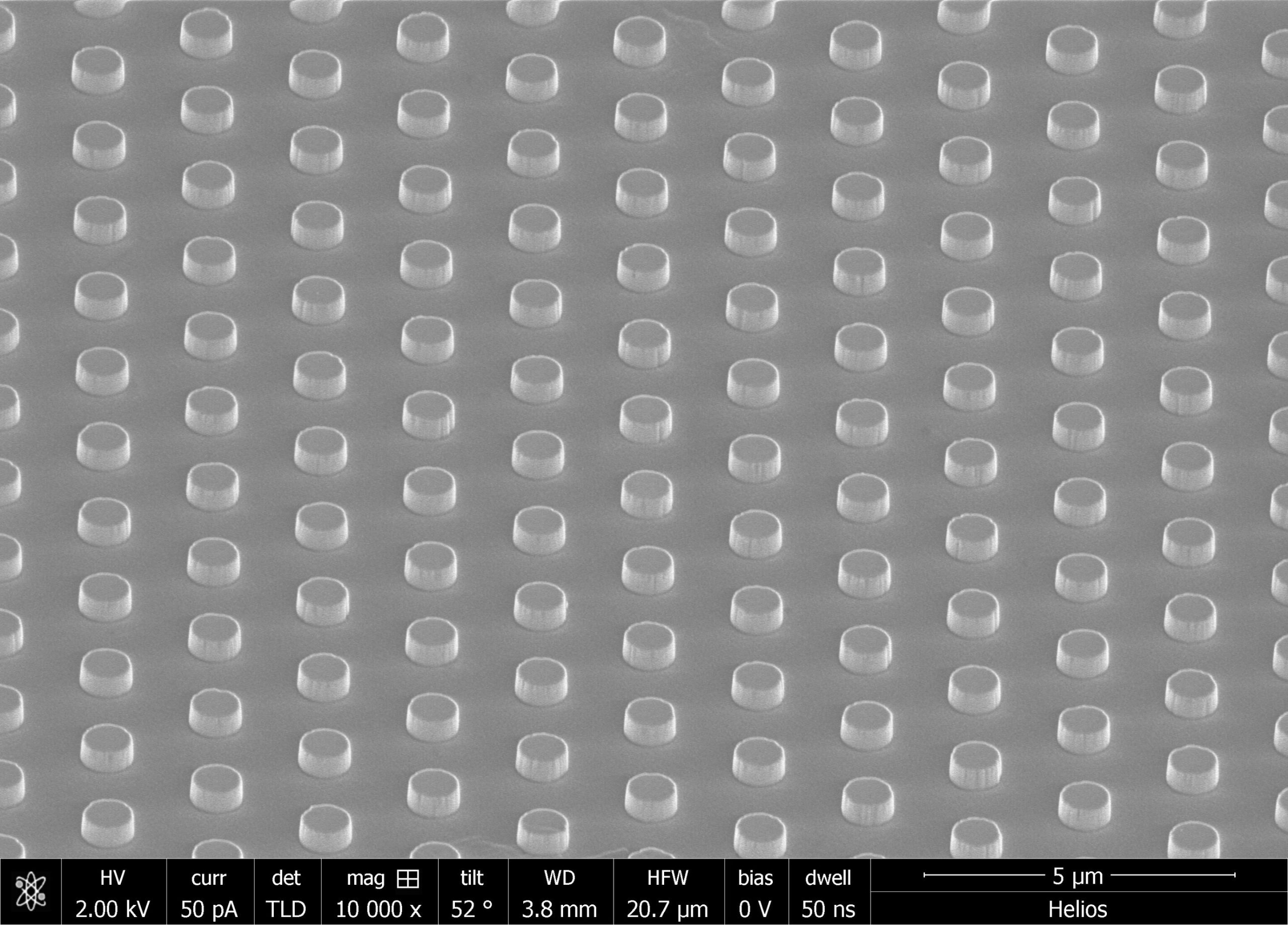
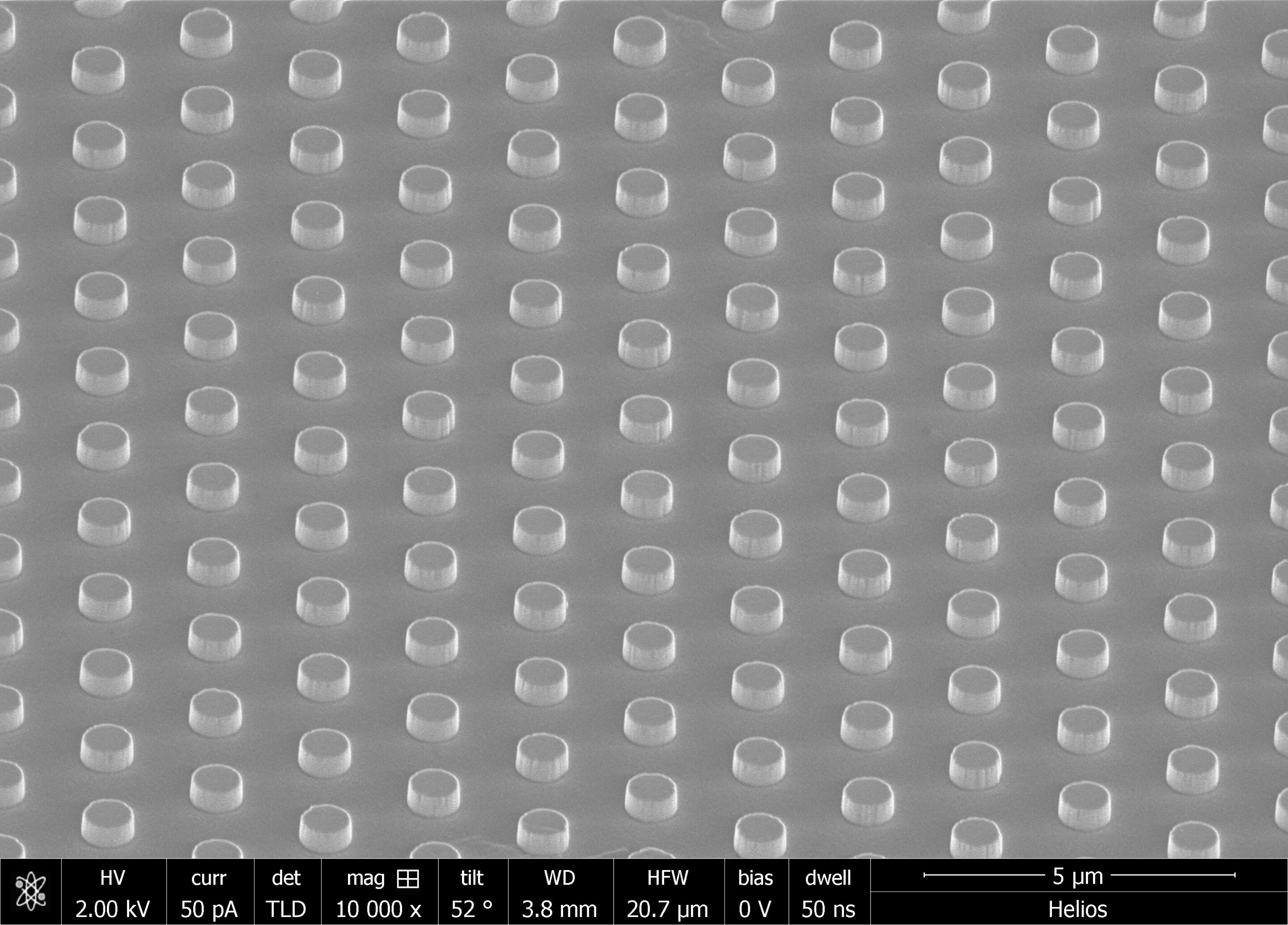
Using tiny arrays of carbon nanotubes, a team of researchers at Rice University has designed nanoscale incandescent light source that could be tuned to precisely emit at specific wavelength, based on the materials’ configuration.
The so-called nanoscale thermal emitters described in a paper titled “Non‐Hermitian Selective Thermal Emitters using Metal–Semiconductor Hybrid Resonators” published in the journal of Advanced Materials combine several known phenomena into a unique system that turns heat into light.
According to the research, the system is highly configurable to deliver light with specific properties and at the desired wavelength. The research is a follow up on a recent technique developed by the lab, using carbon nanotubes to channel heat from mid-infrared radiation to improve the efficiency of solar energy systems.
An electron microscope image shows an array of thermal light emitters created by Rice University engineers. The emitters are able to deliver highly configurable thermal light. Credit: The Naik Lab/Rice University.
Here, the unique design configuration turns heat into light, and is highly configurable.
“The previous paper was all about making solar cells more efficient,” explained Gururaj Naik, an assistant professor of electrical and computer engineering at Rice’s Brown School of Engineering. “This time, the breakthrough is more in the science than the application. Basically, our goal was to build a nanoscale thermal light source with specific properties, like emitting at a certain wavelength, or emitting extremely bright or new thermal light states.
“Previously, people thought of a light source as just one element and tried to get the best out of it,” he said. “But we break the source into many tiny elements. We put sub-elements together in such a fashion that they interact with each other. One element may give brightness; the next element could be tuned to provide wavelength specificity. We share the burden among many small parts”.
“The idea is to rely upon collective behavior, not just a single element,” Naik said. “Breaking the filament into many pieces gives us more degrees of freedom to design the functionality.”
The system relies on non-Hermitian physics, a quantum mechanical way to describe “open” systems that dissipate energy—in this case, heat—rather than retain it. In their experiments, Naik and graduate student Chloe Doiron combined two kinds of near-nanoscale passive oscillators that become electromagnetically coupled when heated to about 700ºC. When the metallic oscillator emits thermal light, it triggers the coupled silicon disk to store the light and release it in the desired manner.
The light-emitting resonator’s output can be controlled by damping the lossy resonator or by controlling the level of coupling through a third element between the resonators. “Semiconductors give you a high selectivity but low brightness, while metals give you very bright emission but low selectivity. Just by coupling these elements, we can get the best of both worlds”, explains Doiron.
“The potential scientific impact is that we can do this not just with two elements, but many more,” Naik said. “The physics would not change.” Although commercial incandescent bulbs have been replaced by LEDs for lighting, incandescent lamps are still the only practical means to produce infrared light, which is necessary for many detection and sensing applications.
“What we’ve created is a new way to build light sources that are bright, directional and emit light in specific states and wavelengths, including infrared.”
Another potential application of these highly selective light sources could be to design of unidirectional nano-optical switches for optical computers. The nanoscale thermal emitters could send light in a specific direction, with none coming back, acting like a diode for light instead of electricity.
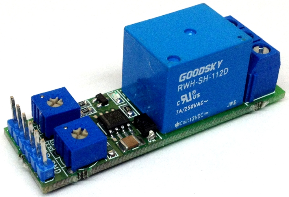
A window detector circuit, also called window comparator circuit or dual edge limit detector circuit is used to determine whether an unknown input is between two precise reference threshold voltages. It employs two comparators to detect over-voltage or under-voltage condition.
This circuit utilizes two comparators in parallel to determine if a signal is between two reference voltages. If the signal is within the window, the output is low thus RELAY is in off condition and also LED is off. Relay provides normally ON and normally OFF switch. If the signal level is outside of the window, the output is high and Relay is in ON condition. For this design, the reference voltages are generated with help of two Trimmer potentiometer. One pot used to set the high voltage level and another one to set the low level voltage adjust. LM358 op-amp used as comparator, it circuit works with 12V DC supply and consumes 50mA current when Relay is in ON state.
Window Comparator – Window Detector with relay output – [Link]
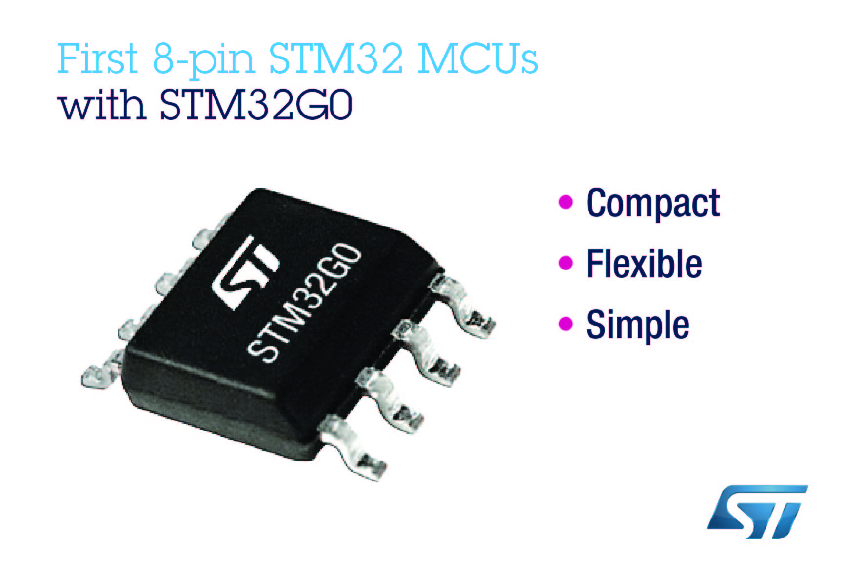
STMicroelectronics has launched a series of STM32 MCUs in an 8-pin package to provide simple embedded projects with 32-bit performance and flexibility in a small, cheap form factor. via www.eenewsembedded.com
The four new STM32G0 devices have a combination of 8-pin economy and a 64MHz Arm Cortex-M0+ CPU providing 59 DMIPS, up to 8Kbyte RAM and 32Kbyte flash on-chip. |The devices also have high-performing peripherals including a 2.5Msps ADC, high-resolution timer, and a high-speed SPI. The internal oscillator is accurate to ±1% over wide temperature and voltage ranges to save external clock components.
Utilising the low-power design features of the STM32 MCU range, the 8-pin STM32G0 devices can be used in energy-conscious applications governed by battery-capacity limits or eco-design legislation.
The new MCUs also provide scalability through the features available across the STM32G0 series, which offers up to 100 package pins, up to 512Kbytes Flash, additional high-performance analogue peripherals, and cyber-protection features.
STM32G0 MCUs are available now in 6mm x 4.9mm SO8N. The 8-pin Discovery kit STM32G0316-DISCO provides quick and affordable evaluation. STM32G031J6, STM32G031J4, and STM32G041J6 Access Line MCUs are also available in SO8N, offering additional functionality including a hardware AES acceleration, Securable Memory Area enabling secure boot or firmware update, extra timers, and 96-bit unique device ID.