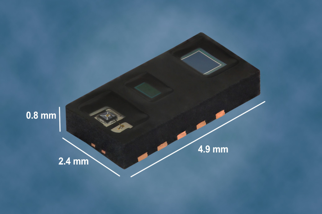
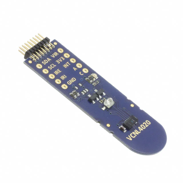
The VCNL4020C is a fully integrated biosensor and ambient light sensor. Fully integrated means that the infrared emitter is included in the package. It has 16 bit resolution. It includes a signal processing IC and features standard I2C communication interface. It features an interrupt function.
Features
Package type: surface-mount
Package form: SMD
Dimensions (L x W x H in mm): 4.90 x 2.40 x 0.83
Integrated modules: infrared emitter (IRED), ambient light sensor (ALS), photo diode (PD), and signal conditioning IC
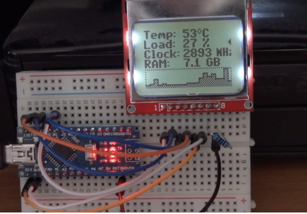
Either for benchmarking purposes or as external telemetry to help you stay within the acceptable range for your computer power, super users usually have the desire to have a way of knowing what the performance numbers of your PC are. For today’s tutorial, we will build a PC Hardware monitor which is capable of obtaining several performance-related parameters from your computer and displaying them on a Nokia 5110 LCD display.
Our PC Hardware monitor tutorial is based on the Arduino Nano microcontroller and a Nokia 5110 LCD Display. We have extensively used both of the components in past tutorials, especially the Nokia 5110 LCD Display for which we have done tutorials on displaying custom graphics, and several more tutorials on creating a custom menu on the display etc.
PC Hardware Monitor with Nokia 5110 Display and Arduino – [Link]
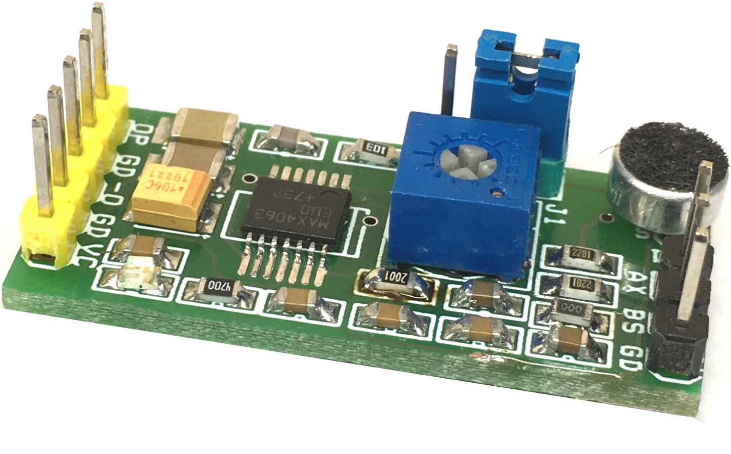
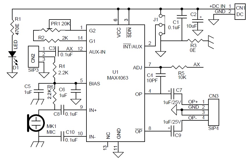
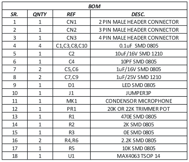
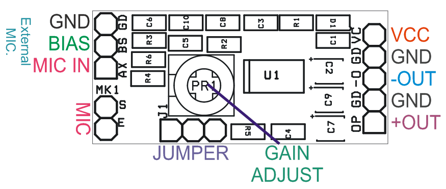
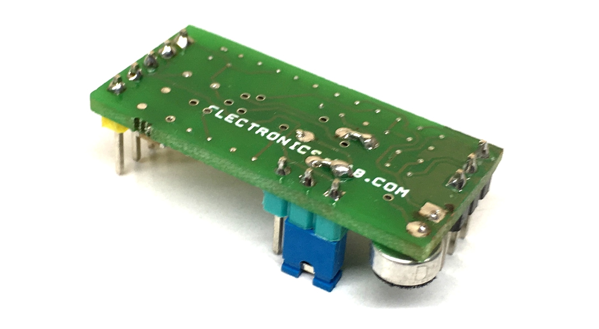
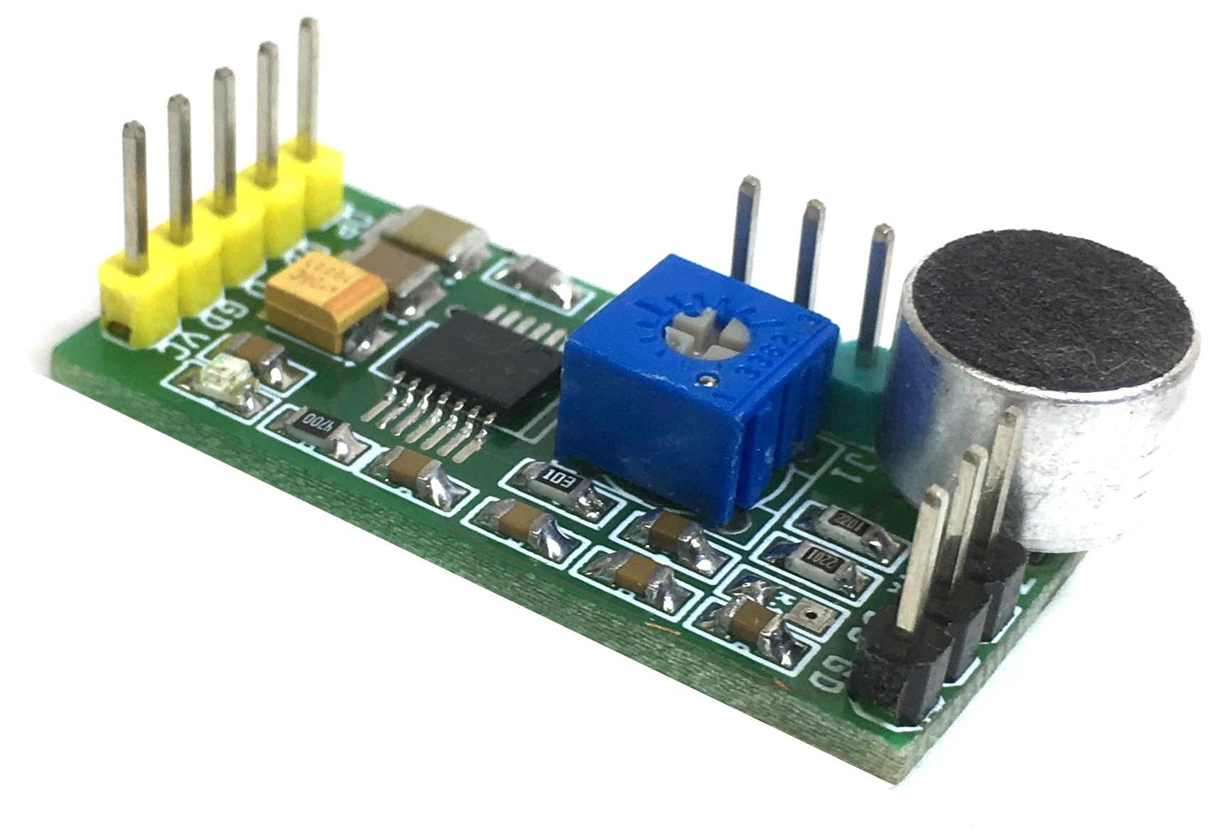
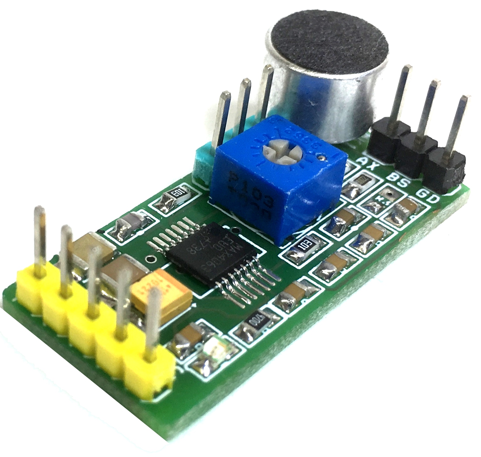
The project shown here is a microphone preamplifier that provides high quality amplification, optimized for use in computers, media and mobile applications. The pre-amplifier provides a differential input stage, making the device particularly effective when layout constraints force the microphone amplifier to be physically remote from the ECM microphone. This project features adjustable gain using PR1 trimmer potentiometer, very high power-supply rejection (95dB), and common-mode rejection (79dB), making it ideal for low-noise applications. Board is provided with condenser microphone as well as connector to connect external microphone, selection of external or internal microphone is possible with the help of on board Jumper. Circuit requires 5V DC input. The circuit provides differential output, use +OP/GND for single ended output. External microphone gain can be changed using R5.
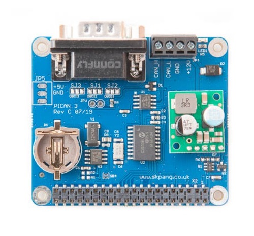
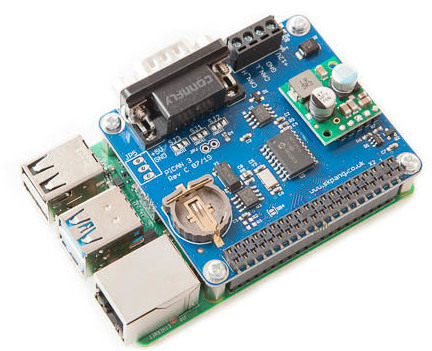
Copperhill Technologies announced the release of its PiCAN3 CAN-Bus Board for the Raspberry Pi 4, adding Controller Area Network capabilities plus a real-time clock to the new Raspberry CPU.
The PiCAN3 board with SMPS (Switch Mode Power Supply) provides CAN-Bus capabilities for the Raspberry Pi 4. It uses the Microchip MCP2515 CAN controller with MCP2551 CAN transceiver. The CAN Bus and power supply connections are made via the onboard DB9 or screw terminal.
There is an easy-to-install SocketCAN driver, and programming can be accomplished in C or Python.
The onboard PCF8523 is a CMOS Real-Time Clock (RTC) and calendar chip optimized for low power consumption. Data is transferred serially via the I²C-bus with a maximum data rate of 1000 kbit/s. Alarm and timer functions are accessible with the opportunity to produce a wake-up signal on an interrupt pin. An offset register allows fine-tuning of the clock. The PCF8523 has a backup battery switch-over circuit, which detects power failures and automatically switches to the battery supply when a power failure occurs.
Features
CAN 2.0B at 1 Mb/s
High speed SPI Interface (10 MHz)
Standard and extended data and remote frames
CAN Bus connection via standard 9-way sub-D connector or screw terminal
Compatible with OBDII cable
Solder bridge to set different configuration for DB9 connector
Onboard 120 Ohm termination resistor
Serial LCD ready
LED indicator
Footprint for two mini push buttons
Four fixing holes, comply with Pi Hat standard
SocketCAN driver, appears as can0 to application
Interrupt RX on GPIO25
5VDC@3A SMPS to power Raspberry Pi and accessories from DB9 or screw terminal
Reverse polarity protection
High efficiency switch mode design
6 VDC to 20 VDC input range
RTC with battery backup (battery not included, requires CR1225 cell)
The Switch Mode Power Supply (SMPS) allows connecting an input voltage range of 6 VDC to 20 VDC, making the board suitable for industrial and automotive applications and environments. The SMPS powers the Raspberry Pi plus PICAN3 and eliminates the need for a Micro-USB power supply.
The PiCAN3 is available for $64.95 with free shipping in the U.S. at Copperhill Technologies. More information may be found in the remarkably hype-free announcement and the PiCAN3 product and shopping page.
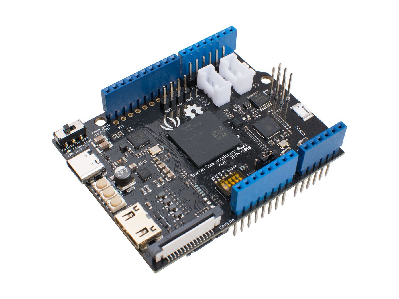
Spartan Edge Accelerator Board is a Xilinx Spartan FPGA development board in the Arduino UNO shield form factor. With the onboard ESP32 chip, it can also provide WiFi and Bluetooth functions.
Arduino – cheap to buy, easy to learn, simple to use, but can’t deal with complex calculations and large projects.
FPGA – flexible and powerful, easily handle complex calculations like audio and video processing, but hard to learn and very expensive.
What if combine the two? Will there be a monster that is expensive, cumbersome and difficult to understand? Of cause not, it will be magic! It will be a game-changer that combines the advantages of Arduino and FPGA and eliminates the shortcomings of both. We present to you the Spartan Edge Accelerator Board!
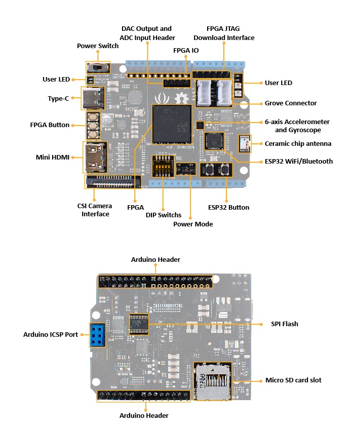
Spartan Edge Accelerator Board is a Xilinx Spartan FPGA development board in the Arduino UNO shield form factor. It can work with Arduino as an FPGA shield and as a stand-alone FPGA development board. With the onboard ESP32 chip, the Spartan Edge Accelerator Board also features 2.4GHz WiFi and Bluetooth 4.1. Moreover, this development board has a wealth of peripherals and interfaces which are extremely playable. Such as an 8-bit ADC, a 6-axis accelerometer, two RGB LEDs, a MINI HDMI interface, a CSI camera interface, two Grove interfaces, etc. All in all, it will be a perfect FPGA board for Makers and Hobbyists.
FPGA
The Spartan Edge Accelerator Board is built around Xilinx Spartan-7 XC7S15 FPGA, which is a cost-effect but powerful FPGA chip. When it comes to Ardunio FPGA, the first mover Arduino MKR Vidor 4000 was always mentioned. Compared with the official Arduino MKR Vidor 4000, the Spartan Edge Accelerator Board has a similar performance, but the price is less than half! Spartan Edge Accelerator Board can run at up to 100Mhz clock speed and offers 12.8K logic cells, 360Kb block RAM. Well, to drive a camera or HDMI display is just a piece of cake. Besides we breakout 10 user-programmable I/O pins of XC7S15, you can configure them as PWM, I2C, I2S, UART, SPI, etc.
ESP32
We know you love ESP32, so we used it as the wireless core. It supports 802.11 b/g/n 2.4GHz WiFi as well as Bluetooth 4.1 with BLE. Just a single board to enable your Arduino with FPGA and Wireless function, isn’t it amazing?
Arduino FPGA API
On top of that, we provide a full Arduino FPGA API to help you use FPGA resources to control FPGA I/Os with Arduino IDE even if you know nothing about the FPGA theory. Spartan Edge Accelerator Board will equip Arduino with the ability that was once unimaginable, such as edge technology, image recognition, signal sampling and processing, and so on.
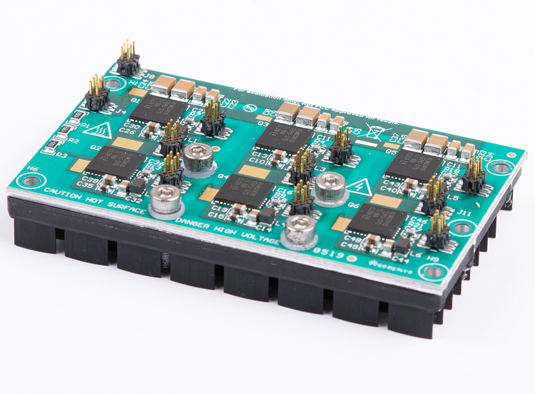
This reference design is a three-phase inverter with a continuous power rating of 1.25 kW at 50°C ambient and 550 W at 85°C ambient for driving 200-V AC servo motors. It features 600-V LMG3411R150 Gallium Nitride (GaN) power modules with an integrated FET and gate driver mounted on an 1.95-mm Insulated Metal Substrate (IMS) board for efficient heat dissipation. Isolation and control circuits are mounted on separate FR-4 boards – the dimensions of the design are 80 mm × 46 mm × 37 mm, including heatsink, control, isolation, and power stage. This ultra-small form factor, coupled with the ability to be natural convection fanless cooled, allows for easy integration of the drive with the motor, reducing the required cabinet space by up to 50% and cable lengths by up to 90 m in 6-axis motor applications including robotics, CNC machines, and so forth.
Features
600 V, 6-A LMG3411R150 GaN enables a power density of 150 W/in3 in 50°C ambient conditions up to 1.25 kW and in 85°C ambient conditions up to 550 W
Ultra-small form factor and natural convection fanless cooling allows easy integration of the drive with the motor-saving floor space and cabling costs
Very fast switching transition (<5 ns) with minimal switch node voltage ringing reduces EMI
High-efficiency power stage (peak efficiency >99% at 32-kHz PWM) reduces heat-sink size
Protection against gate undervoltage, device overcurrent, and overtemperature
Definitely, Arduino has made it easy for anyone to learn electronics and programming of modern microcontrollers. Not only that, it had brought out a new era of creative makers, just by the single thought, Arduino makes it possible to bring your ideas to life within a fraction of time without costing you a lot.
The Arduino ecosystem has grown large with many tools, kits, resources available everywhere on the internet. For the total newbie, it is easy to get overwhelmed on where to start. Maybe starting reading through Instructables, Hackaday, or even through the Arduino Playground and our own Arduino Projects, you might still get overwhelming without proper guidance.
When starting to learn electronics, Arduino is usually the most suggested route to go. People will tend to advise newbies to go buy an Arduino kit to get started, I do recommend this as well, but the problem is what kit you should go for? There are hundreds of Arduino kits roaming around the internet covering different skillets from Beginners to Advanced users, but which one should you go for?
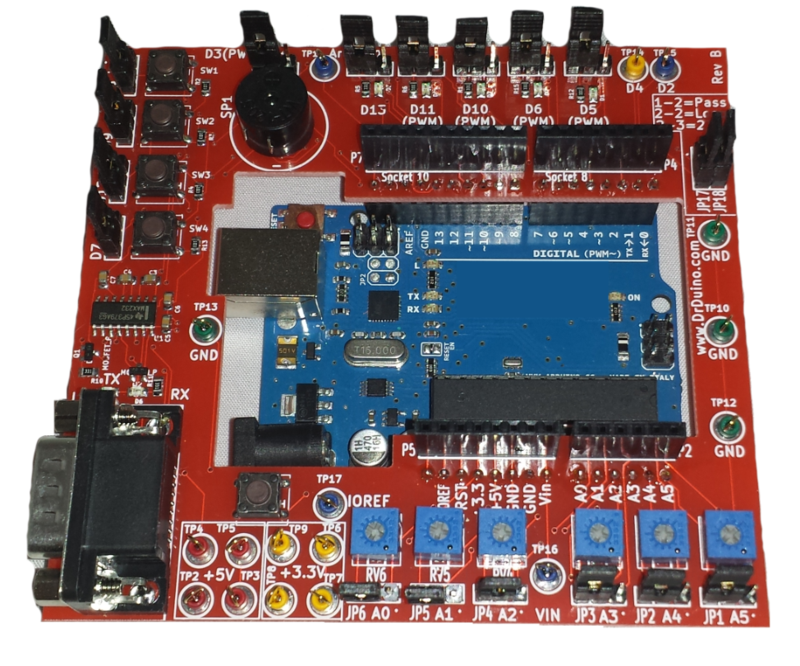
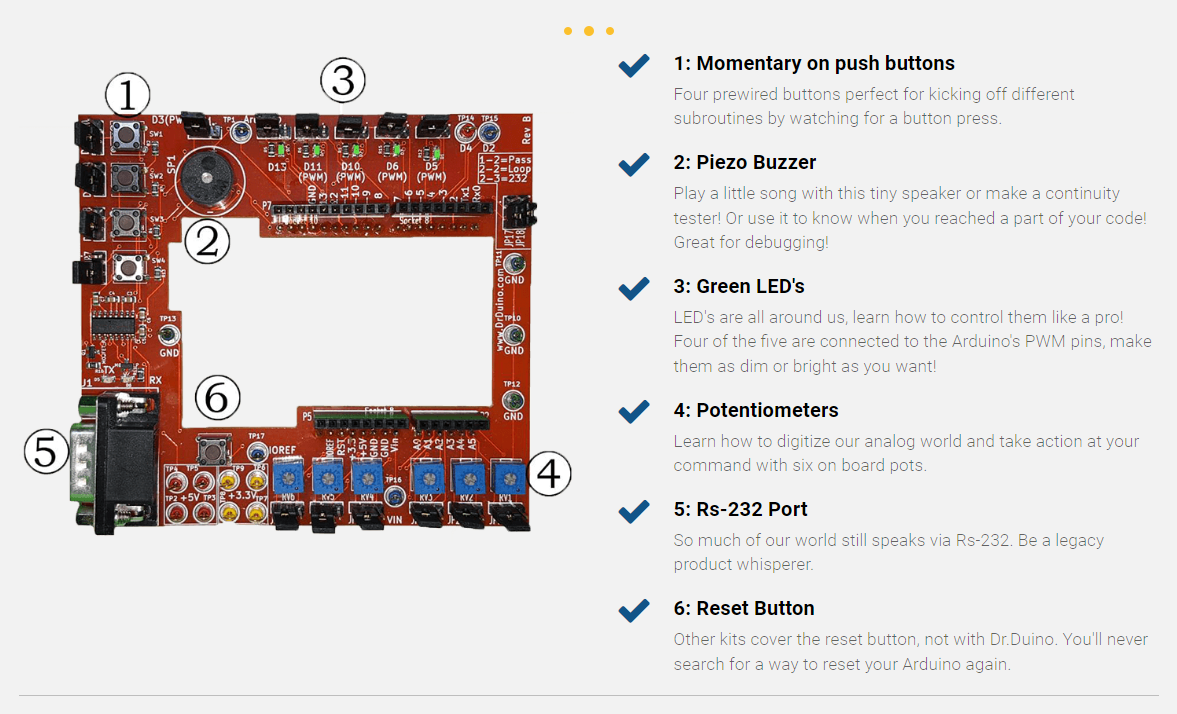
dr.Duino board attached to Arduino
If you are in this dilemma, you probably don’t have to worry anymore with the discovery of Dr.Duino Arduino Uno Starter Kit. The Arduino Uno Starter Kit is an Arduino kit tailored for both pure beginners and advanced users.
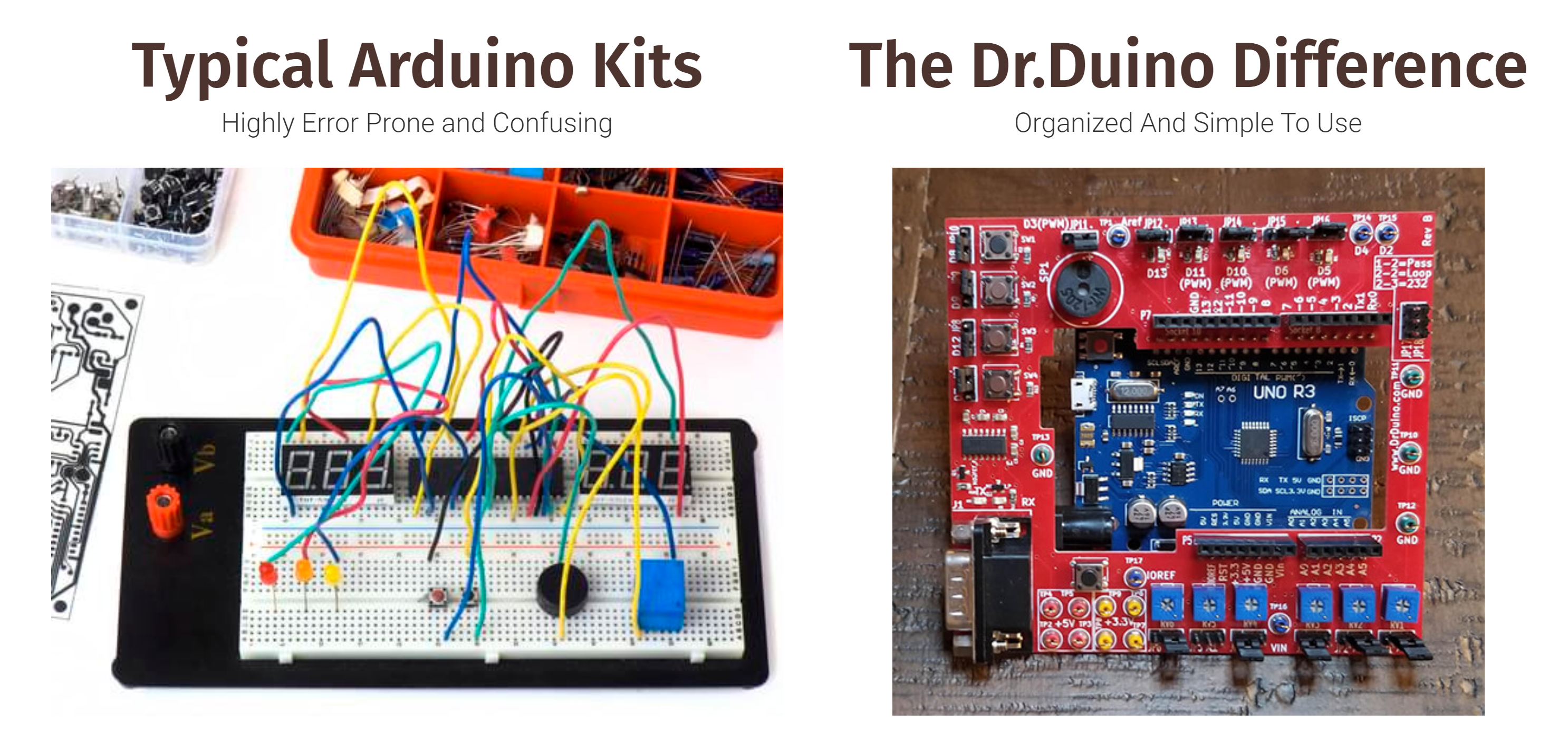
Dr.Duino Arduino Starter kit attempts to address one major concern of beginners – Frustration on building your Arduino circuits. When working on an electronics project, you will tend to make all your connections on a breadboard, using jumpers or wires to connect things. Depending on the level of connections needed, it is easy to run into a messy breadboard connection which in most cases don’t usually work after the first attempt, and then you will have to spend hours trying to fix the issue, only to realize it’s connected to wrong spot in the breadboard.
The Dr.Duino Difference
Dr.Duino kit solves this as it has all of the same components other kits have but one major difference! It’s pre-wired so you can focus on learning to code.
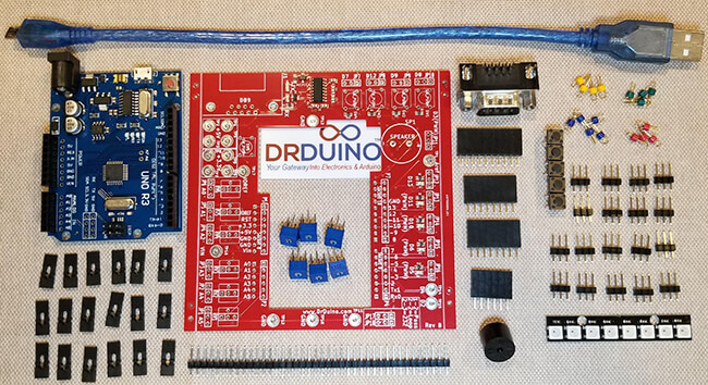
The kit comes with the following:
An Arduino Uno Compatible Board
Switches x 4
Piezo Buzzer
LED’s x 5
Potentiometers x 6
RS-232 Port
Arduino Reset Button
A bare board.
For advanced users – it comes with a special “re-route it technology”. Dr.Duino uses a unique but simple jumper structure to re-route the signal from the board above, out to the Dr.Duino itself. This feature allows you to isolate firmware from hardware bugs. Also, the Dr. Duino shield can work with other Arduino shields and boards.
Some other benefits include:
Exclusive Access To the Dr.Duino VIP Facebook Group
An exclusive offer for a FREE Arduino programming course
Dr. Duino Arduino Uno Starter Kit
The Dr.Duino kit does require some simple soldering (through hole components only) which typically takes about 6-90 minutes. With its highly detailed instructions, this is one fun kit to build!
Where the Dr.Duino really shines is in its ability to help you isolate hardware from coding issues and also but acting as a simulator.
The Dr.Duino kit allows the user to to attach scope probes and other test equipment without resorting to shoving wires into the female sockets and/or attaching alligator clips which often times fall off.
As a simulator, since it has all of the most common circuits prebuilt into the shield itself, you can also use it to simulate sensors which you may not have on hand.
For example, maybe you need to write a piece of code which turns on a LED when someone gets too close to an object. But if you don’t have an ultra sonic sensor on hand what do you do?
Well just use the potentiomenter to feed in various voltage levels to simulate someone moving close or far away from the sensor. Once you have the correct value selected, just pop on your sensor and your off and running!
In conclusion, the Dr.Duino Starter kit for the Arduino Uno is jam packed with features you won’t find on any other Arduino kit out on the market today.
For a limited time you can purchase one for $49.00 as compared to the original $118 price. You can purchase the kit from the product page. More information is available on the sales page.
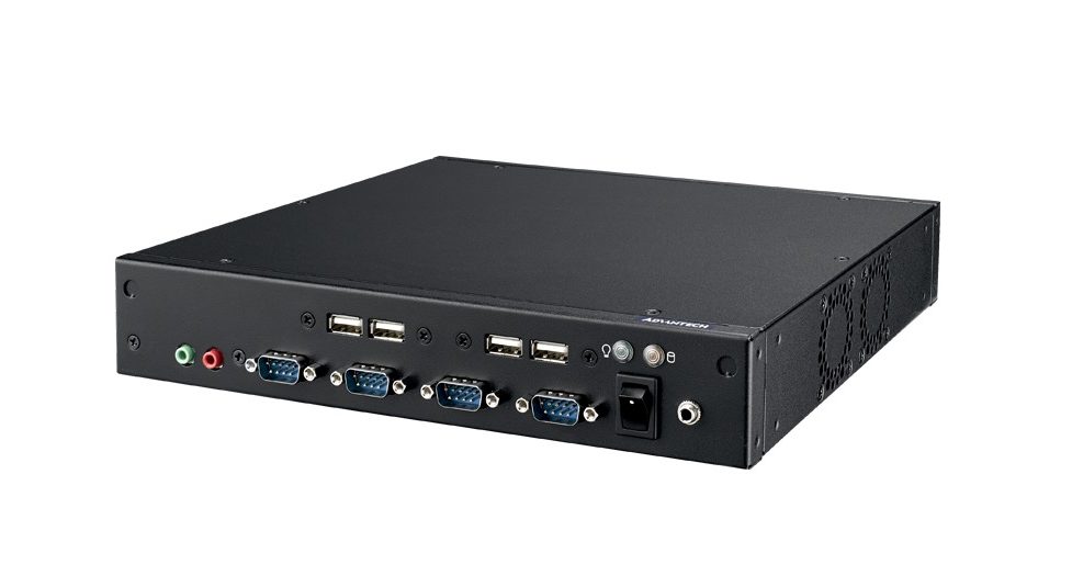
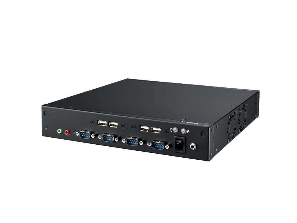
Advantech, a leading embedded computing solution provider, announced the release of its latest new 1U THIN barebone system with 8th Gen. Intel® Core™ processors up to 65W TDP – EPC-T2286
This system supports Intel® 8th generation Core™ i7/i5/i3 processors which bring enhanced performance over previous generations with up to six CPU cores and Intel’s 9th generation graphics engine. EPC-T2286 powers up to two independently operated 60 Hz 4K displays via DisplayPort or HDMI and supports Wall/ VESA/ rack mounting for flexible easy installation.
THIN Design w/Desktop CPU for Space-limited Applications
The compact 1U height EPC-T2286 is just 250 x 44.2 x 225 mm. It offers the high processing capability of a desktop CPU with up to six CPU cores and Intel® 8th Core™ i7/i5/i3 and Pentium/Celeron® processors to deliver high computing power and graphic performance. The Intel® H310 Express chipset supports Dual Channel DDR4 2666MHz memory (up to 32GB) in two SODIMM slots. Features include integrated Intel® Gen 9 graphics (Display Port, HDMI), triple gigabit Ethernet w/ EtherCAT capability, 6 x serial ports (2x RS-232/422/485 by BOM option), and ESD level 4 protection compliance. All these features make EPC-T2286 well suited to kiosk or automation applications needing a compact 1U height chassis.
Easy to Install, Connect, and Maintain
To fulfill space limited kiosk or automation application requirements, the 1U THIN EPC-T2286 offers different mounting kits for installation into various cabinets and spaces. EPC-T2286 has 6 x COM ports, 8 x USB ports, DP, and HDMI which allows it to easily connect to RFID readers, thermal printers, Key PAD, touch screens, 4k displays and so on. SI or tool machine builders can easily integrate the whole system and shorten their time to market. Furthermore, the ESD level 4 (contact 8kv and air 15kv) design offers better ESD protection for automation applications operating in harsh environments. EPC-T2286 is a modular system and provides ease of maintenance in the field.
Remote management & monitoring for IoT Applications
A core advantage of EPC-T2286 is that it comes equipped with Advantech’s WISE-PaaS/DeviceOn software solution designed to simplify IoT application integration. WISE-PaaS/DeviceOn is an IoT device management software platform which includes remote device, monitor, control, event management, system management, and software over-the-air update. WISE-PaaS/DeviceOn not only helps create new web services but also helps to integrate functions and data with its powerful management tools. WISE-PaaS highly enhances connectivity for hardware, software, devices and sensors, and helps customers to transform their business to include IoT cloud services.
EPC-T2286 Desktop System Features:
THIN design only 1U in height
The latest 8th generation Intel® Core™ i / Pentium/ Celeron processors up to 65W TDP
Designed to support unattended operation, IP65+, and passive cooling
Have you ever tried designing a truly embedded x86-based system? We have, and it was a journey full of unexpected pitfalls.
Consider the importance of unattended operation, including resilience in the face of power failures and power voltage fluctuation. Need support for different CPU models? A compact, IP65+ enclosure? Each of these requirements is tricky on its own; taken together, they begin to feel insurmountable. But wandering into previously uncharted territory is half the fun of engineering, and we at Fairwaves are not ones to shy away from a challenge!
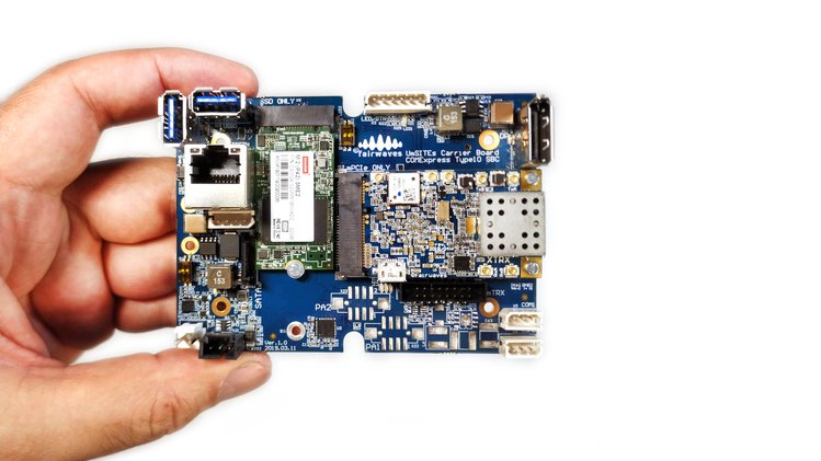
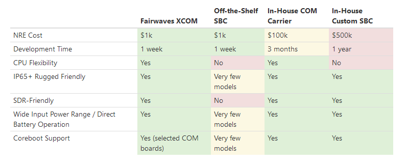
Today, we are making the results of more than a year’s worth of development available to the world. With the launch of XCOM, no one ever needs to face this particular set of challenges again.
We designed XCOM to be the ultimate platform for the Fairwaves UmTRX and XTRX Software Defined Radios (SDRs), but it works just as well with other USB, Ethernet, and miniPCIe SDRs. We have already started using the first revision of XCOM in our OpenRAN cellular base stations, and the version that will ship at the end of this campaign will incorporate everything we have learned from that field experience.
We also believe that XCOM has many applications outside of the SDR space. If you have suggestions for how we could make XCOM even more useful for non-SDR projects, please reach out and let us know!
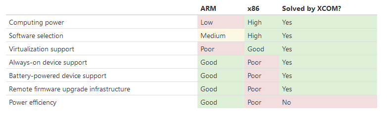
XCOM Handles Demanding CPU and I/O Requirements
These days, a lot of control boards are based on ARM chips because they are small, inexpensive, power-efficient, and embedded-friendly. But what if you need more CPU power or faster I/O than an ARM chip can provide?
What if, for example, you are working in the growing field of Software-Defined Radio (SDR) and the RF processing of your application demands intensive Digital Signal Processing (DSP) and high throughput I/O? You could use a specialized DSP chip or an FPGA, but processing your data on a sufficiently powerful x86 CPU is not only simpler, it also benefits from a more developed software ecosystem and easy virtualization.
The downside of using x86 is a less developed ecosystem of truly embedded, unattended designs. A lot of x86-based embedded systems are used in point-of-sale terminals, measurement devices, and other equipment that are easy to access and therefore easy to restart or fix if something goes wrong. For our use case, we need equipment that adheres to the infamous telecom standard of 99.999% uptime, even though it might be hundreds of kilometers – and many hours of driving – away from anyone who could fix it. Or it might be deep under water. Or hanging from a weather baloon. Or orbiting the Earth!
Building an x86-based device that is always on when it’s connected to power, and that can be reliably reflashed to a new software release remotely is surprisingly non-trivial. We had to pay special attention to everything from hardware design to Coreboot support to make it possible.
Features
RF Power Amplifiers (PAs) control. XCOM uses the same PA control as our classic UmTRX SDR:
Two software-controlled, high-load DCDCs to control the RF output power of the PAs
Four ADCs to measure the forward and reflected power of two PAs for VSWR calculation
GPIO to turn PAs on and off
miniPCIe with 2x PCIe lanes. Unlike most miniPCIe slots, which provide only one PCIe lane, XCOM allows you to utilize the full bandwidth of XTRX SDR.
EEPROM with one write-lockable page. Allows you to store hardware-specific settings in a software-independent way. Unlike SSD, EEPROM is soldered on the board and is not changed when you re-install the OS. A write-lockable page allows you to store unique IDs, security keys, and other data that should not be changed by end-users.
Coreboot support (selected COM modules only). Unlike a proprietary BIOS, Coreboot is open-source and modular, which allows essential customization of the boot process for unattended, always-on operation. By way of example:
Coreboot allows safe, remote upgrades of its own firmware (with support for recovery and production images).
Coreboot can provide a simple recovery OS and can, for example, dial home and report an issue even in the case of SSD failure.
Coreboot settings can be flashed onto the image and do not require a CMOS battery, which is a frequent point of failure.
System indicators, such as LEDs, can be programmed to start almost immediately after XCOM is powered on and well before the OS is loaded. They can also be programmed to indicate various boot failures.
To simplify recovery, netboot can be configured to start if a particular combination is sent over a serial console.
Only vertical connectors. The classic side connectors used in most SBCs do not work well in small IP65+ enclosures. They require extra space around the board to plug in cables, and once the board is installed, those cables becomes virtually impossible to unplug. All of XCOM’s connectors are vertical, so the board occupies only the space required by its own footprint. Vertical connectors also make it easy to plug and unplug cables when the board is mounted in an enclosure.
Designed for passive cooling. We took special care to ensure that XCOM can be used in environments – like inside an IP65+ enclosure – where active cooling is not possible.
The project shown here is a microphone preamplifier that provides high quality amplification, optimized for use in computers, media and mobile applications. The pre-amplifier provides a differential input stage, making the device particularly effective when layout constraints force the microphone amplifier to be physically remote from the ECM microphone. This project features adjustable gain using PR1 trimmer potentiometer, very high power-supply rejection (95dB), and common-mode rejection (79dB), making it ideal for low-noise applications. Board is provided with condenser microphone as well as connector to connect external microphone, selection of external or internal microphone is possible with the help of on board Jumper. Circuit requires 5V DC input. The circuit provides differential output, use +OP/GND for single ended output. External microphone gain can be changed using R5.
The project features two selectable inputs onboard microphone or external microphone, differential outputs, adjustable gain, an integrated low noise bias source, and a low-power shutdown mode. Two input paths provide both differential and single ended microphone sensing. The high-noise rejection of the differential input is ideally suited to an internal microphone where system noise and long-run PC board traces can degrade low-level signals. The single-ended input provides a simple connection to an external microphone, can be connected to CN2.