PC Hardware Monitor with Nokia 5110 Display and Arduino

Either for benchmarking purposes or as external telemetry to help you stay within the acceptable range for your computer power, super users usually have the desire to have a way of knowing what the performance numbers of your PC are. For today’s tutorial, we will build a PC Hardware monitor which is capable of obtaining several performance-related parameters from your computer and displaying them on a Nokia 5110 LCD display.

Our PC Hardware monitor tutorial is based on the Arduino Nano microcontroller and a Nokia 5110 LCD Display. We have extensively used both of the components in past tutorials, especially the Nokia 5110 LCD Display for which we have done tutorials on displaying custom graphics, and several more tutorials on creating a custom menu on the display etc.

The principle of operation of today’s project is based on the “Grant SnattsHardware Serial Monitor project, which in turn, is based on the SerialSender utility which uses the open-source OpenHardwareMonitorLib.dll to sniff the sensors of the dedicated GPUs, graphic Cards, CPU and motherboards of most modern personal computers whilst, also pooling windows hardware stats. This stats and data are then obtained by the Arduino over the serial port and displayed on the Nokia 5110 LCD display.  To do a better than other versions of the project out there, rather than just displaying the data, we will plot performance graphs to show information the CPU Load and the CPU Clock.

At the end of today’s tutorial, you would know things like graph plotting etc on the Nokia 5110 as well as interacting with the PC directly using the Arduino.

Required Components

The following components are required to build this project.

  1. Arduino Nano or Arduino Pro Mini with USB to serial adapter
  2. Nokia 5110 LCD
  3. Jumper Wires
  4. Breadboard

These components can be bought from any electronic components store online.

Schematics

The schematics for this project is simple and should be familiar if you have been following several of our tutorials. Since the project is made up of just two main components, all we need to do is connect the Nokia 5110 LCD Display to the Arduino as shown in the schematics below;

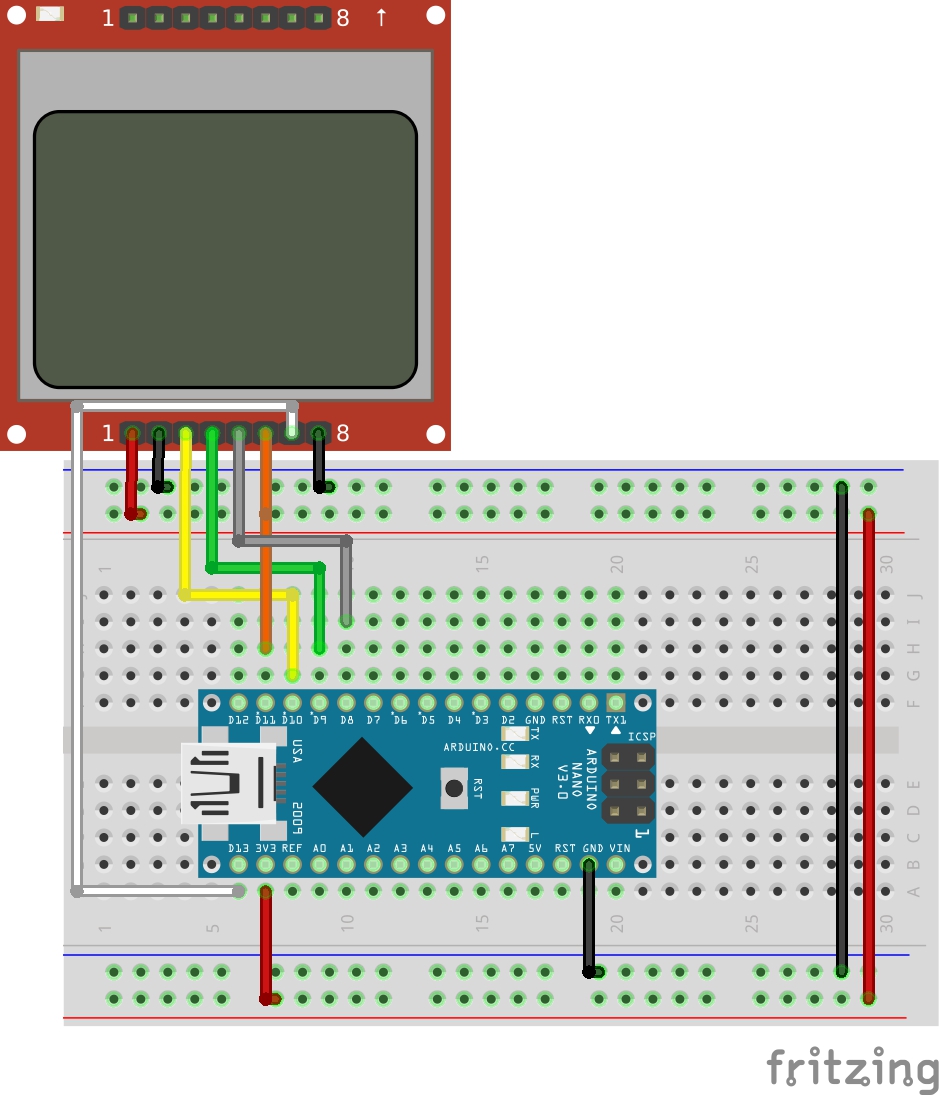
To further make the connection easy to follow, a pin to pin connection between the Arduino and Nokia 5110 LCD display is described below.

Nokia 5110 – Arduino 

VCC - 3.3V
GND - GND
DC - D8
RST - D9
CS/CE - D10
MOSI/DIN - D11
SCK/CLK - D13
LIGHT  - GND

Go over the connections once more to ensure everything is as it should be.

Code

The code for this project is quite straight forward. We obtain PC performance information via serial communication from the hardware monitor utility and display on the LCD as a graph and in raw data form.

To achieve this, we use N5110_SPI.h minimalistic Arduino library by cbm80amiga. The library uses a very small amount of MCU resources and contains methods that reduce the amount of code you need to write to display data on the Nokia 5110 LCD.

As usual, I will be doing a brief run through the code to explain some of its technical parts.

We start the sketch by including the libraries that we will use. In addition to the N5110_SPI library, we will use two fonts libraries; c64enh_font.h and small5x7bold_font.h They are attached under the download section.

#include "N5110_SPI.h"
// from PropFonts library
#include "c64enh_font.h"
#include "small5x7bold_font.h"

Next, we create an instance of the N5110_SPI library with the Arduino pins to which its, RST, CS, and DC pins are connected as arguments.

// define USESPI in above header for HW SPI version
N5110_SPI lcd(9,10,8); // RST,CS,DC

#if USESPI==1
#include <SPI.h>
#endif

We then choose if we want to display the load graph or clock graph.

// comment out for load graph
#define CLOCK_GRAPH

Next, create other variables that will be used in the code to store information retrieved from the PC among others.

String inputString = "";
char buf[30];
String cpuLoadString;
String cpuTempString;
String cpuClockString;
String ramString;
int cpuLoad=0;
int cpuClock=0;
int inp=0;
#define MIN_CLOCK 400
#define MAX_CLOCK 2900
#define NUM_VAL (21)
int valTab[NUM_VAL];
int i,ght=16;
int x=0;

Next, We write the void setup function. We start the function by initializing the serial monitor which we will use for debug purposes. Next, we initialize the LCD, set the font and display the string “Connecting” at the center of the screen.

void setup() 
{
  Serial.begin(9600);
  inputString.reserve(200);
  
  lcd.init();
  lcd.clrScr();
  lcd.setFont(c64enh);
  lcd.printStr(ALIGN_CENTER, 2, "Connecting ...");
}

With that done, we create the function readSerial. This function does 80% of the work involved in this project. The function picks up the data sent by the utility over serial and extracts the CPU Clock, the RAM usage, CPU temperature and CPU load information from the serial data stream.

int readSerial() 
{
  while (Serial.available()) {
    char ch = (char)Serial.read();
    inputString += ch;
    if(ch == '|') {  // full info chunk received
      int st,en;
      st = inputString.indexOf("CHC");  // CPU clock: "CHC1768"
      if(st>=0) {
        en = inputString.indexOf("|", st);
        cpuClockString = inputString.substring(st+3, en);
        cpuClock = cpuClockString.toInt();
        inp=3;
      } else {

        st = inputString.indexOf("R");  // used RAM: "R6.9"
        if(st>=0) {
          en = inputString.indexOf("|", st);
          ramString = inputString.substring(st+1 , en-1);
          st = ramString.indexOf(",");
          if(st>=0) ramString.setCharAt(st,'.');
          inp=2;
        }

        int cpuTempStart = inputString.indexOf("C"); // CPU temperature: "C52"
        int cpuLoadStart = inputString.indexOf("c"); // CPU load: "c18%"
        if(cpuLoadStart>=0 && cpuTempStart>=0) {
          en = inputString.indexOf("|");
          cpuTempString = inputString.substring(cpuTempStart+1, cpuLoadStart);
          cpuLoadString = inputString.substring(cpuLoadStart+1, en-1);
          cpuLoad = cpuLoadString.toInt();
          inp=1;
        }
      }
      inputString = "";
      return 1;
    }
  }
  return 0;
}

Next, is the void loop() function. The void loop function checks to see if the serial data is available by calling the readserial function. If data is available from the PC, it then displays the extracted data from the readserial() function on the LCD Display, while also using the LCD.fillWin() and drawGraphBar() function to plot the graph.

void loop() 
{
  //readSerial();
  if(readSerial()) 
  {
    int xs=38;
    lcd.setFont(c64enh);
    lcd.printStr(0, 0, "Temp: ");
    x=lcd.printStr(xs, 0, (char*)cpuTempString.c_str());
    lcd.printStr(x, 0, "'C  ");
    lcd.printStr(0, 1, "Load: ");
    snprintf(buf,20,"%d %",cpuLoad);
    x=lcd.printStr(xs, 1, buf);
    lcd.printStr(x, 1, "%  ");
    lcd.printStr(0, 3, "RAM: ");
    x=lcd.printStr(xs, 3, (char*)ramString.c_str());
    lcd.printStr(x, 3, " GB  ");
    lcd.printStr(0, 2, "Clock: ");
    x=lcd.printStr(xs, 2, (char*)cpuClockString.c_str());
    lcd.setFont(Small5x7PLBold);
    lcd.printStr(x, 2, " MHz    ");
#ifdef CLOCK_GRAPH
    i = 2;
#else
    i = 1;
#endif
    lcd.fillWin(83,i,1,1,B00111110);
    lcd.fillWin(82,i,1,1,B00011100);
    lcd.fillWin(81,i,1,1,B00001000);

    if(inp==3) addVal();
    clrBuf();
    drawGraphBar();
    lcd.drawBuf(scr,0,4,scrWd,scrHt);
  }
  if(inp>=3) { delay(1000); inp=0; }
}

The complete code for the project is available below and under the download section. It contains all the other functions that were used and is well commented so it should be easy to follow irrespective of your programming experience.

#include "N5110_SPI.h"
// from PropFonts library
#include "c64enh_font.h"
#include "small5x7bold_font.h"

// define USESPI in above header for HW SPI version
N5110_SPI lcd(9,10,8); // RST,CS,DC

#if USESPI==1
#include <SPI.h>
#endif


// comment out for load graph
#define CLOCK_GRAPH

String inputString = "";
char buf[30];
String cpuLoadString;
String cpuTempString;
String cpuClockString;
String ramString;
int cpuLoad=0;
int cpuClock=0;
int inp=0;
#define MIN_CLOCK 400
#define MAX_CLOCK 2900
#define NUM_VAL (21)
int valTab[NUM_VAL];
int i,ght=16;
int x=0;


void setup() 
{
  Serial.begin(9600);
  inputString.reserve(200);
  
  lcd.init();
  lcd.clrScr();
  lcd.setFont(c64enh);
  lcd.printStr(ALIGN_CENTER, 2, "Connecting ...");
}

int readSerial() 
{
  while (Serial.available()) {
    char ch = (char)Serial.read();
    inputString += ch;
    if(ch == '|') {  // full info chunk received
      int st,en;
      st = inputString.indexOf("CHC");  // CPU clock: "CHC1768"
      if(st>=0) {
        en = inputString.indexOf("|", st);
        cpuClockString = inputString.substring(st+3, en);
        cpuClock = cpuClockString.toInt();
        inp=3;
      } else {

        st = inputString.indexOf("R");  // used RAM: "R6.9"
        if(st>=0) {
          en = inputString.indexOf("|", st);
          ramString = inputString.substring(st+1 , en-1);
          st = ramString.indexOf(",");
          if(st>=0) ramString.setCharAt(st,'.');
          inp=2;
        }

        int cpuTempStart = inputString.indexOf("C"); // CPU temperature: "C52"
        int cpuLoadStart = inputString.indexOf("c"); // CPU load: "c18%"
        if(cpuLoadStart>=0 && cpuTempStart>=0) {
          en = inputString.indexOf("|");
          cpuTempString = inputString.substring(cpuTempStart+1, cpuLoadStart);
          cpuLoadString = inputString.substring(cpuLoadStart+1, en-1);
          cpuLoad = cpuLoadString.toInt();
          inp=1;
        }
      }
      inputString = "";
      return 1;
    }
  }
  return 0;
}


void addVal()
{
  for(i=0;i<NUM_VAL-1;i++) valTab[i]=valTab[i+1];
#ifdef CLOCK_GRAPH
  if(cpuClock<400) cpuClock=400;
  if(cpuClock>2900) cpuClock=2900;
  valTab[NUM_VAL-1] = (long)(cpuClock-MIN_CLOCK)*ght/(MAX_CLOCK-MIN_CLOCK);
#else
  valTab[NUM_VAL-1] = cpuLoad*ght/100;
#endif
}

// --------------------------------------------------------------------------
byte scr[84*2];  // frame buffer
byte scrWd = 84;
byte scrHt = 2;

void clrBuf()
{
  for(int i=0;i<scrWd*scrHt;i++) scr[i]=0;
}

void drawPixel(int16_t x, int16_t y, uint16_t color) 
{
  if((x < 0) || (x >= scrWd) || (y < 0) || (y >= scrHt*8)) return;
  switch (color) {
    case 1: scr[x+(y/8)*scrWd] |=  (1 << (y&7)); break;
    case 0: scr[x+(y/8)*scrWd] &= ~(1 << (y&7)); break; 
    case 2: scr[x+(y/8)*scrWd] ^=  (1 << (y&7)); break; 
  }
}

void drawLineH(uint8_t x0, uint8_t x1, uint8_t y, uint8_t step)
{
  if(step>1) { if(((x0&1)==1 && (y&1)==0) || ((x0&1)==0 && (y&1)==1)) x0++; }
  if(x1>x0) for(uint8_t x=x0; x<=x1; x+=step) drawPixel(x,y,1);
  else      for(uint8_t x=x1; x<=x0; x+=step) drawPixel(x,y,1);
}

void drawLineV(int x, int y0, int y1, int step)
{
  if(step>1) { if(((x&1)==1 && (y0&1)==0) || ((x&1)==0 && (y0&1)==1)) y0++; }
  if(y1>y0)for(int y=y0; y<=y1; y+=step) drawPixel(x,y,1);
  else     for(int y=y1; y<=y0; y+=step) drawPixel(x,y,1);
}

// --------------------------------------------------------------------------

void drawGraphBar()
{
  drawLineH(0,83,0,2);
  drawLineH(0,83,15,2);
  drawLineV(0,0,15,2);
  drawLineV(83,0,15,2);
  for(i=0;i<NUM_VAL;i++) {
    drawLineH(i*4,(i+1)*4-1,15-valTab[i],1);
    drawLineV(i*4+0,15-valTab[i],15,2);
    drawLineV(i*4+1,15-valTab[i],15,2);
    drawLineV(i*4+2,15-valTab[i],15,2);
    drawLineV(i*4+3,15-valTab[i],15,2);
    if(i>0) drawLineV(i*4,15-valTab[i-1],15-valTab[i],1);
  }
}

void loop() 
{
  //readSerial();
  if(readSerial()) 
  {
    int xs=38;
    lcd.setFont(c64enh);
    lcd.printStr(0, 0, "Temp: ");
    x=lcd.printStr(xs, 0, (char*)cpuTempString.c_str());
    lcd.printStr(x, 0, "'C  ");
    lcd.printStr(0, 1, "Load: ");
    snprintf(buf,20,"%d %",cpuLoad);
    x=lcd.printStr(xs, 1, buf);
    lcd.printStr(x, 1, "%  ");
    lcd.printStr(0, 3, "RAM: ");
    x=lcd.printStr(xs, 3, (char*)ramString.c_str());
    lcd.printStr(x, 3, " GB  ");
    lcd.printStr(0, 2, "Clock: ");
    x=lcd.printStr(xs, 2, (char*)cpuClockString.c_str());
    lcd.setFont(Small5x7PLBold);
    lcd.printStr(x, 2, " MHz    ");
#ifdef CLOCK_GRAPH
    i = 2;
#else
    i = 1;
#endif
    lcd.fillWin(83,i,1,1,B00111110);
    lcd.fillWin(82,i,1,1,B00011100);
    lcd.fillWin(81,i,1,1,B00001000);

    if(inp==3) addVal();
    clrBuf();
    drawGraphBar();
    lcd.drawBuf(scr,0,4,scrWd,scrHt);
  }
  if(inp>=3) { delay(1000); inp=0; }
}

Demo

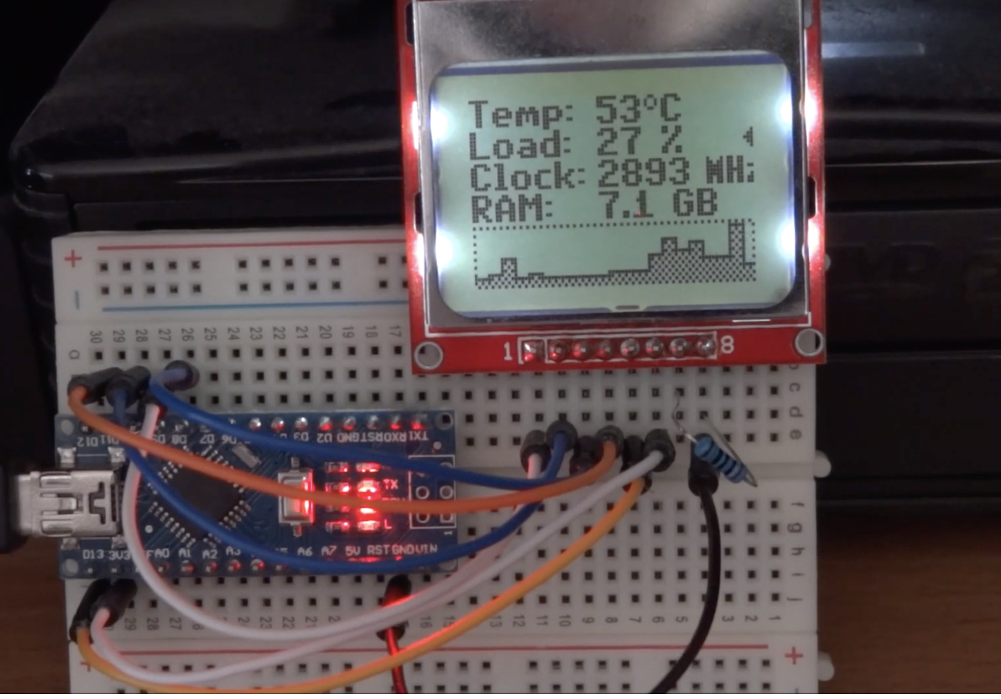
With the code complete and the hardware connected as described under the schematics, connect the Arduino board to the computer and upload the code. Launch the hardware monitor software (attached under the download section) as an administrator and select the right com port to match the port on which your Arduino board is connected.

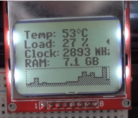
With this done, you should see the screen come up with PC performance information being displayed as shown in the image below.

To take things forward and improve on the project, how about we make things wireless?

That’s it for this tutorial, thanks for reading along. Feel free to reach out to me via the comment section with any question you might have about it.

The project is based on the work of cbm80amiga, you can watch a video of the device in action on youtube.

Wi-Fi 6 milestone reached

Wi-Fi 6, the newest generation of Wi-Fi connectivity, reached a significant milestone a few days ago with official certification. The Wireless Broadband Alliance (WBA) is the not-for-profit industry body for the Wi-Fi ecosystem whose members include BT, AT&T and Google.

The organization’s General Manager, Tiago Rodrigues states on this development:

“This is the point at which Wi-Fi 6 starts to become mainstream – it’s the end of the beginning.  Up until now, Wi-Fi 6 has been the domain of pioneers and pilots, including some of our members like Korea Telekom, SK Telekom, Cisco and Boingo Wireless. Those pilots and early deployments have been happening for some time, but now with the launch of Wi-Fi 6 CERTIFIED®, a much larger volume of wireless operators and enterprises will be more confident investing in Wi-Fi 6 devices and infrastructure, which ultimately benefits businesses and consumers.  This will likely create a virtuous circle, where hardware manufacturers and service providers will likewise become more focused on addressing the growing appetite for Wi-Fi 6.”

“In terms of what happens next on the ground, we’ll see service providers and likely early adopters like venues and the hospitality and retail sectors exploring their options with Wi-Fi 6.  There are still some things to watch out for and challenges to be addressed – it won’t necessarily be a straight rip-and-replace of existing equipment, as there will need to be some more planning and re-configuring to tackle the opportunity optimally.  That’s why we created our Wi-Fi 6 Deployment Guidelines to smooth the transition out and make the most of this huge leap in Wi-Fi capability.”

Toradex works with Amazon Web Services and NXP on a cloud-enabled AI demonstration

Toradex leverages Amazon® Web Services (AWS) and NXP® to demonstrate how to simplify the creation of Industry 4.0-ready industrial automation solutions. A live demonstration that leverages expertise and technology across all three companies will be on display at the Industry of Things World in Berlin from September 16 through September 17.

The demo includes:

  • NXP’s high performance MX 8QuadMax application processor, optimized for safety and reliability
  • AWS IoT Greengrass and Amazon SageMaker Neo, which provide optimized machine learning at the device edge, plus seamless online and offline capabilities
  • Toradex’s easy-to-use Computer on Modules/System on Modules and software, which simplify development and maintenance while lowering time to market

The demo is built around a conveyor belt simulating a factory automation line. A MIPI CSI Camera is used to detect and classify objects. Different types of pasta are used as an example for this showcase. The demo shows how to solve many challenges faced in today’s smart factories, some of which include:

  • Secure connectivity for integrations with business tools, remote monitoring, updates, etc.
  • Maximum uptime and reliability even with intermittent connectivity
  • Small rugged and cost-optimized computing hardware
  • Use of the latest technologies in computer vision and machine learning
  • Short time to market and limited development resources

It highlights how the collaboration between these companies simplifies many of the steps required to build advanced industrial automation equipment for Industry 4.0.

In the future, this demo will be made available as a starting point to reduce the risk and time to market.

More information on the Hardware:

Toradex’s Apalis iMX8QM System on Module features NXP’s i.MX 8 QuadMax SoCs. The i.MX 8 applications processor family is built with a high-level integration to support graphics, video, image processing, audio, and voice functions, and is ideal for safety-certifiable and efficient performance requirements.

The Apalis modules come with Torizon, an easy-to-use industrial Linux platform offered by Toradex. AWS IoT Greengrass runs on the device, providing connectivity and offline capabilities.

The demo has a local graphical user interface, as well as a cloud-based control dashboard hosted on AWS.

With Amazon SageMaker a neural network was trained to detect and classify different types of pasta. The trained network was optimized with Amazon SageMaker Neo for the Apalis iMX8QM, resulting in increased performance and efficiency.

 To learn more and see the demo in action, visit AWS at Industry of Things World Berlin on September 16 and 17.

If you can’t make it, stay tuned for more information on the demo, or reach out to your local Toradex office.

Free Elektor Article: USB Pseudo Battery

  • Original publication: Elektor magazine September 2015, page 102
  • Author: Danny Winkler
  • Free download expires: Friday 20 September 2019
  • Elektor PCB available: yes, low stock. Extra boards available by 23 September 2019, please check article page
  • Please Note: Four years since its original publication, the referred article may contain components, software elements and/or linked urls that require updating to the present moment

Go to the article page and download a pdf copy of the magazine article. Downloading is free until Friday 20 September, 2019

Indoor Solar Cells optimised to convert ambient indoor light to electricity

Swedish and Chinese scientists have developed organic solar cells optimised to convert ambient indoor light to electricity. The power they produce is low, but is probably enough to feed the millions of products that the internet of things will bring online. For more information see the IDTechEx report on Energy Harvesting Microwatt to Megawatt 2019-2029.

As the internet of things expands, it is expected that we will need to have millions of products online, both in public spaces and in homes. Many of these will be the multitude of sensors to detect and measure moisture, particle concentrations, temperature and other parameters. For this reason, the demand for small and cheap sources of renewable energy is increasing rapidly, in order to reduce the need for frequent and expensive battery replacements.

This is where organic solar cells come in. Not only are they flexible, cheap to manufacture and suitable for manufacture as large surfaces in a printing press, they have one further advantage: the light-absorbing layer consists of a mixture of donor and acceptor materials, which gives considerable flexibility in tuning the solar cells such that they are optimised for different spectra – for light of different wavelengths.

read more

Vishay Intertechnology’s New Cost-Effective Proximity Sensor Provides Sensing Distance Up to 30 cm

The Optoelectronics group of Vishay Intertechnology, Inc. (NYSE: VSH) today introduced a new proximity sensor that offers a sensing distance of up to 30 cm. Combining an IR emitter, photo detectors for proximity, amplifiers, and ADC circuitry into a single package, the Vishay Semiconductors VCNL3040 features a programmable interrupt function and supports the I²C bus communication interface for efficient object and collision detection in a wide variety of consumer and industrial applications.

Ideally suited for use in smart home, industrial, office, and toy products, the device released today provides a 33 % increase in proximity detection distance compared to previous-generation sensors at a lower cost than similar solutions on the market. Applications include presence detection to activate displays in printers, copiers, and home appliances; collision detection in robots and toys; vehicle occupancy detection in parking lots; and proximity detection in lavatory appliances.

Product Benefits:

  • Sensing distance up to 30 cm
  • Programmable interrupt function allows designers to specify high and low thresholds, which reduces the continuous communication with the microcontroller
  • Supports I²C bus communication interface
  • Selectable 12-bit and 16-bit outputs • Intelligent cancellation eliminates cross-talk
  • Smart persistence scheme ensures accurate sensing and faster response time
  • Emitter wavelength peaks at 940 nm and has no visible “red-tail”
  • Excellent temperature compensation from -40 °C to +85 °C • Offered in a lead-free 8-pin QFN package
  • RoHS-compliant, halogen-free, and Vishay Green

The VCNL3040’s programmable interrupt function allows designers to specify high and low thresholds, which reduces the continuous communication with the microcontroller. Featuring selectable 12-bit and 16-bit outputs, the proximity sensor uses intelligent cancellation to eliminate cross-talk, while a smart persistence scheme ensures accurate sensing and faster response time. The emitter wavelength peaks at 940 nm and has no visible “red-tail.”

The device offers a supply voltage range of 2.5 V to 3.6 V, an I²C bus voltage range from 1.8 V to 3.3 V, and excellent temperature compensation from -40 °C to +85 °C. Offered in a lead-free 8-pin QFN package, the sensor is RoHS-compliant, halogen-free, and Vishay Green.

Samples and production quantities of the new VCNL3040 are available now, with lead times of eight to 12 weeks for large orders.

CHUWI UBook Pro is a Low-Cost Alternative to Microsoft Surface Pro 6

Introduction UBook Pro

The latest 2-in-1 tablet/laptop from CHUWI, is the UBook Pro, that the Chinese manufacturer hopes will rival the Microsoft Surface Pro 6. The company has been manufacturing tablet/laptop computers since 2013. They targeted the mobile office industry with the UBook, and now the UBook Pro, with focus on versatility, quality, performance, and portability.

Processor Improvements

UBook Pro has some interesting enhancements to their original tablet. The processor is the first big change, being an upgrade from an Intel Core m3-6Y30 processor of the previous UBook tablet, to a high-efficiency 8th Gen Intel Core m3-8100Y processor with a claimed overall increase in performance of 50% compared to the original UBook tablets.

Display Ability

The 12.3-inch FHD IPS full lamination screen has a 3:2 ratio, which can be found on the Surface Pro, HUAWEI Matebook and others, delivers a vivid picture with exceptional resolution. The design is meant for the office work of many types and built to be used in the mobile office environment.

Storage and Stylus

The 128/256 GB M.2 SSD is able to read and write at up to 500MB/s compared to the eMMC of the UBook, this performance increase means the UBook Pro saves much faster than before and helps with start-up speeds and application loading. The stylus pressure sensitivity is increased from 1024 to 2048 in the HiPen H5, which is applicable to stroke thickness and the handwriting accuracy, which can translate into more complex graphics and improved handwriting capability.

Keyboard Enhancements

The keyboard has the same key switches as the Surface series and the back-lit keyboard design has improved the overall typing experience, which is suited to the mobile office capability that the UBook Pro is built to deliver.

UBook Pro Specs:

  • CPU: Intel Core m3-8100Y, 3.4 GHz, 2C4T
  • GPU: UHD Graphics 615, 900MHz
  • Display: 12.3’’ IPS full-laminated, 1920 * 1280, multi-touch screen
  • RAM: 8GB RAM, 128GB/256G SSD
  • Battery: 37Wh
  • I / 0 Ports: Full-featured USB-C, USB-A 3.0 * 2, Micro-HDMI, 3.5mm audio jack
  • OS: Windows 10 Home
  • Expected Price: around $600

UBook Pro Features, Size and Weight

The U-Shape kickstand at the back is made for a step-less adjustment, that can offer a max opening of 145° offering convenience and efficiency, as a tablet, workstation or laptop, in a wide variety of locations. Equipped with Intel UHD Graphics 615, making 4K hardware video decoding available. The tablet is a slim 9 mm thick and weighs a mere 780 g making the units extremely easy to carry and setup.  The fanless design makes the UBook Pro silent and cool-to-the-touch.

Intro Video

More Information

The IndieGoGo Campaign is to be announced and the cost of the units will probably run about $600 USD before shipping. There is a contest for a free UBook Pro to be announced once the IndieGoGo Campaign is kicked off. You can find more details and register for a 25% discount in the pre-launch page.

via www.cnx-software.com

Boardcon Idea3399 Feature-Rich SBC Comes with M.2 NVMe SSD and 4G LTE PCIe Sockets

A few years back, Boardcon introduced EM3399 single board computer powered by a Rockchip RK3399 processor through the company’s PICO3399 SO-DIMM system-on-module.

They’ve now designed another RK3399 based SBC , the Idea3399 – comprised of a baseboard and module, but instead of re-using the SO-DIMM module, CM3399 system-on-module with castellated holes was used instead. The new board comes with many of the same features as their first board but adds an M.2 NVMe SSD slot and mPCIe socket for 4G LTE modem on the back of the board.

CM3399 SoM

Key features and specifications:

  • SoC – Rockchip RK3399 dual Cortex-A72 @ 1.8GHz + quad Cortex-A53 @ 1.4GHz
  • System Memory – 4GB LPDDR4
  • Storage – 8GB eMMC flash
  • 202 castellated pin (1.3mm pitch) with  USB2.0 host, USB3.0 host, USB OTG, UART, MIPI, Ethernet, SPI, HDMI out, I2C, I2S, PCI Express, SDIO, SD/MMC, eDP, Camera, PWM, ADC IN, etc…
  • Power – Supply Voltage: 5V; RK808 PMU
  • Dimensions – 55  x 50mm (8 Layers, complying with EMS/EMI)

The module comes with Android 7.1.2 preinstalled and targets AIoT applications such as intelligent interactive devices, personal computers, and robots. The Android BSP is based on  Linux 4.4.126 and the cross-compilation toolchain runs on Ubuntu 16.04.

Idea3399 SBC

Idea3399 SBC specifications:

  • SoM – CM3399 module described above
  • Storage – MicroSD card slot, M.2 2280 NVMe SSD slot
  • Video Output / Display I/F
    • 1x mini Display Port
    • 1x HDMI 2.0 port up to 4Kp60
    • Up to 2x MIPI DSI interface for LCD (1x multiplexed with MIPI CSI)
  • Audio – Realtek ALC5651 Audio CODEC, 3.5mm jack for headphone, 14-pin header for MIC Array, digital audio via HDMI
  • Camera – Up to 2x MIPI CSI interface for 13MP camera (1x multiplexed with MIPI DSI); Optional OV13850 camera sensor (13MP)
  • Connectivity
    • Gigabit Ethernet (RTL8211E)
    • Dual-band (2.4GHz/5GHz) 802.11 a/b/g/n/ac WiFi 5 and Bluetooth 4.1
    • Optional 3G/4G LTE mPCIe card + SIM card slot
  • USB – 1x USB2.0 host port, 2x USB 3.0 Type-C ports
  • Serial
    • 4-wire UART1 (Multiplexed signal with Ethernet), 1x 8pin connector
    • 3-pin debug UART2
    • 4-wire UART3 (Multiplexed signal with Ethernet), 1x 4pin connector
  • Expansion Headers – 8-pin for SPI
  • Misc – IR receiver; recovery, power and reset buttons; CR1220 battery for RTC
  • Power Supply – DC 5V/3A or 3.6V~12.8V Li-Ion battery; 2x 5-pin power header; 2×4-pin PoE header
  • Dimensions – 135mm x 90mm

None of the software and related documentation is available publicly, but they do have some hardware documentation and datasheets which you’ll find on the product pages for the SoM and SBC respectively. Pricing has not been made public, but I understand the board and module have been available since late July.

via www.cnx-software.com

Axiomtek’s eBOX100-51R-FL – A Fanless Ultra Compact Embedded System for Edge Computing

Axiomtek – a world-renowned leader relentlessly devoted in the research, development and manufacture of series of innovative and reliable industrial computer products of high efficiency – is proud to unveil eBOX100-51R-FL, a fanless ultra-compact embedded system with weight 600 grams only. As the smallest embedded system with Intel® Core™ ULT processor onboard, the eBOX100-51R-FL continues the design elements of eBOX100 series – ultra-slim form factor, rugged design, and rich I/O connectivity, allowing greater flexibility and a wider range of application in edge computing, IIoT gateway and extended fields.

The eBOX100-51R-FL is powered by the high-performance Intel® Core™ i5-7300U or Intel® Celeron® 3965U processor. The front-facing I/O connectivity design provides convenient access for easy installation and maintenance. It comes with one DDR4-2133 SO-DIMM slot with system memory up to 16 GB. The eBOX100-51R-FL offers two RS-232/422/485, two USB 3.0 ports, two USB 2.0 ports, two Gigabit Ethernet ports, one DisplayPort++, one AT/ATX quick switch, and two SMA type antenna openings; moreover, the embedded system is equipped with one M.2 Key E 2230 slot for Wi-Fi, one M.2 Key B 2242 for SATA storage, and one screw-type 12VDC power input connector.

“Axiomtek’s eBOX100-51R-FL has multiple mounting options for versatile use in various environments. Not only could it be wall mounting or VESA mounting, but also supports the DIN-rail mounting for typical industrial application. The flexible mounting options satisfied user requirements and easy deployment.” said Janney Lee, a product manager of Product PM Division at Axiomtek. “Besides, the ultra-compact embedded platform is compatible with Windows® 10 IoT and Linux. With an IP40-rated heavy-duty aluminum extrusion and steel case, it has a wide operating temperature range of -10°C to 50°C and vibration endurance for up to 3G. It has passed the strict certification with CE and FCC Class A.”

Advanced Features:

  • Ultra-compact size with high performance
  • Intel® Core™ i5-7300U or Celeron® 3965U (codename: Kaby Lake)
  • M.2 Key E 2230 for Wi-Fi
  • M.2 Key B 2242 for storage
  • Azure certified and AXView 3.0 supported
  • Supports Intel® AMT 11
  • Multiple mounting designs: Wall mount, DIN-rail and VESA mount

In tandem with helping customers to enhance the effectiveness in remote management, the outstanding eBOX100-51R-FL supports Axiomtek’s exclusive AXView 3.0 software, Intel® AMT 11 and Microsoft Azure. The reliable Intel® Core™-based embedded system provides customers an ideal solution for factory automation, industrial IoT edge computing, digital signage, kiosk, and smart retail. Axiomtek’s eBOX100-51R-FL is now available for purchase. For more product information or customization services, please visit our global website at www.axiomtek.com or contact one of our sales representatives at info@axiomtek.com.tw.

Minimal I2C for the New AVR Microcontrollers

This article describes a set of minimal I2C routines for the new 0-series and 1-series ATtiny and ATmega microcontrollers. They allow any of these processors to act as an I2C Master and connect to I2C peripherals. As an example of their use I’ve designed a digital clock circuit based on a 0-series ATtiny402 connected to an I2C RTC module and driving an I2C 7-segment display.

The main difference between these routines and the standard Arduino Tiny Wire library is that these don’t use buffers, so have minimal memory requirements, and don’t impose a limit on transmissions.

Note that these routines are designed for the latest ATtiny 0-series and 1-series processors, and the 0-series ATmega chips; if you want minimal I2C routines for the earlier ATtiny processors, such as the ATtiny85, see my earlier article Minimal Tiny I2C Routines.

Minimal I2C for the New AVR Microcontrollers – [Link]

TOP PCB Companies