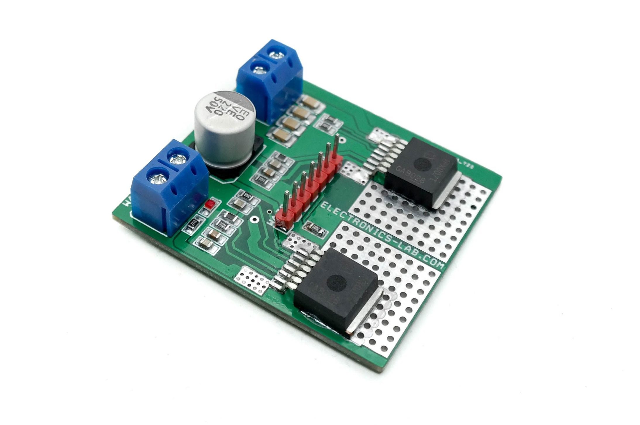
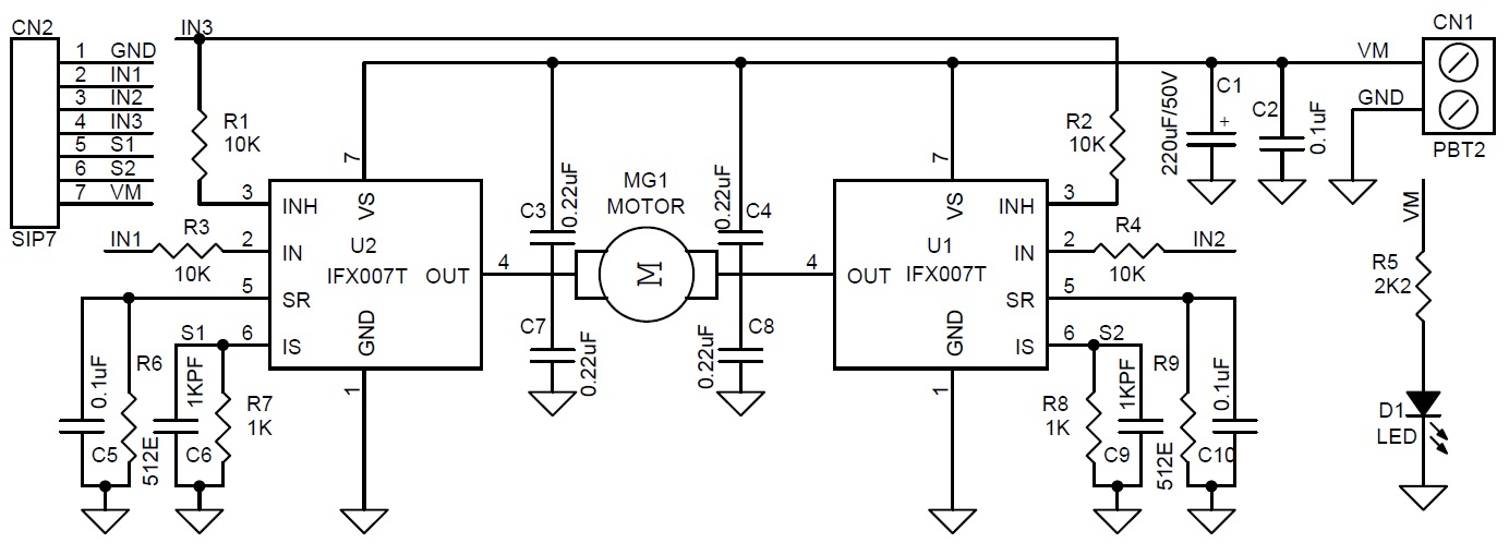
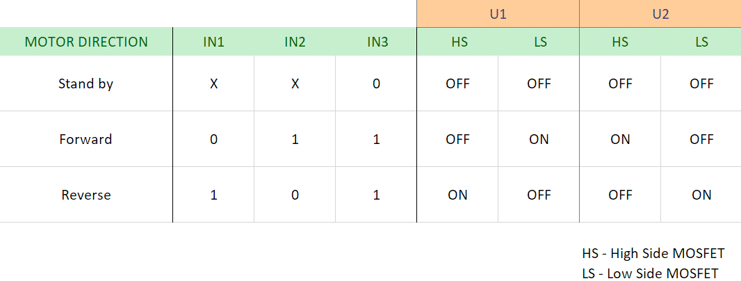
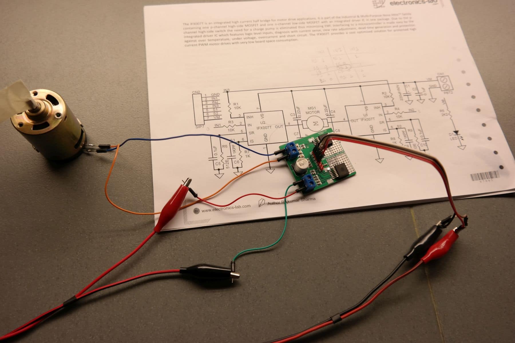
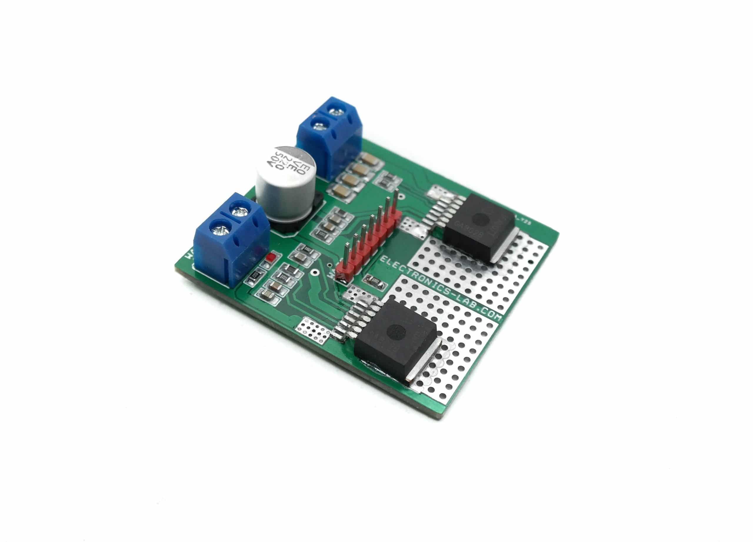
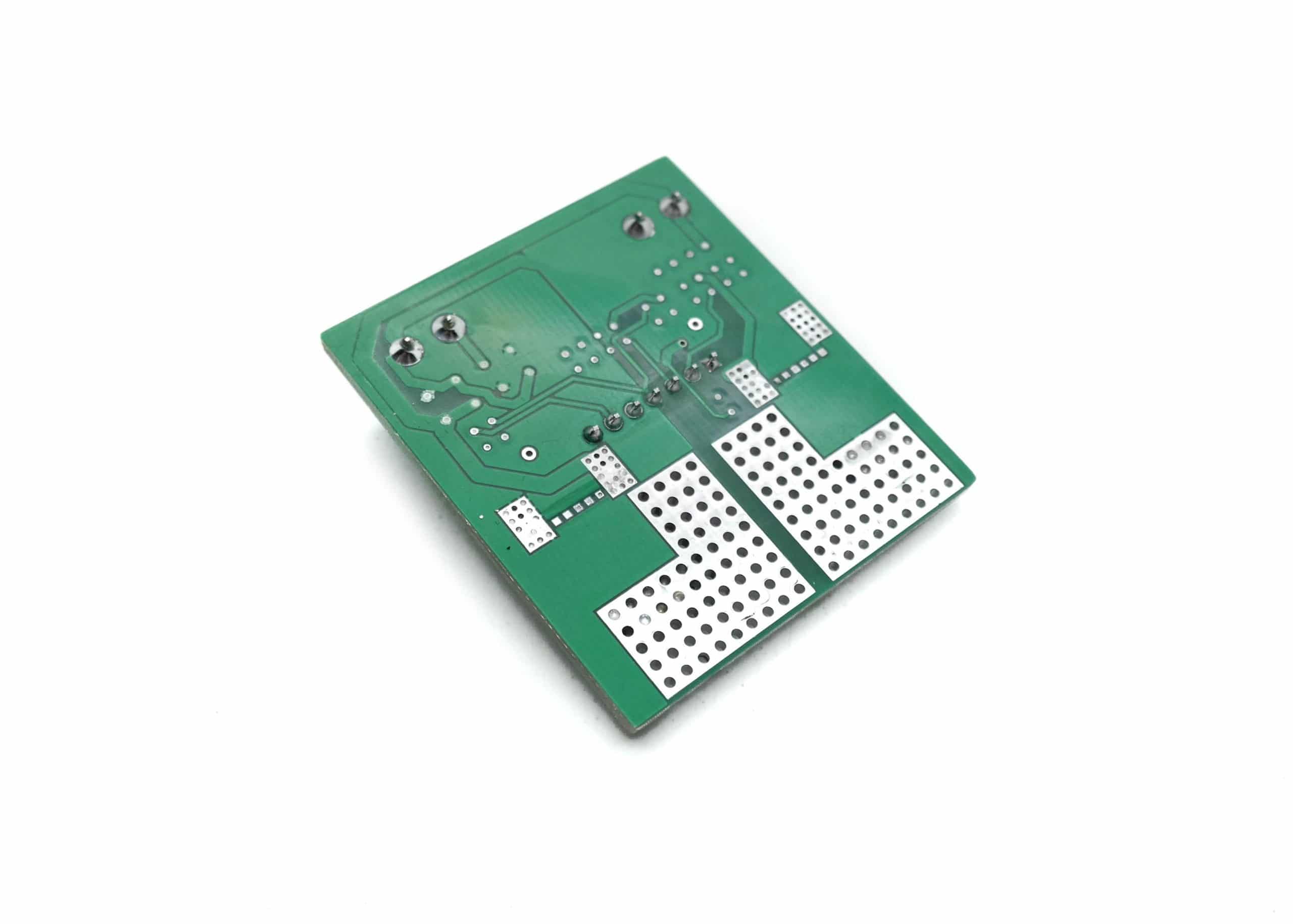
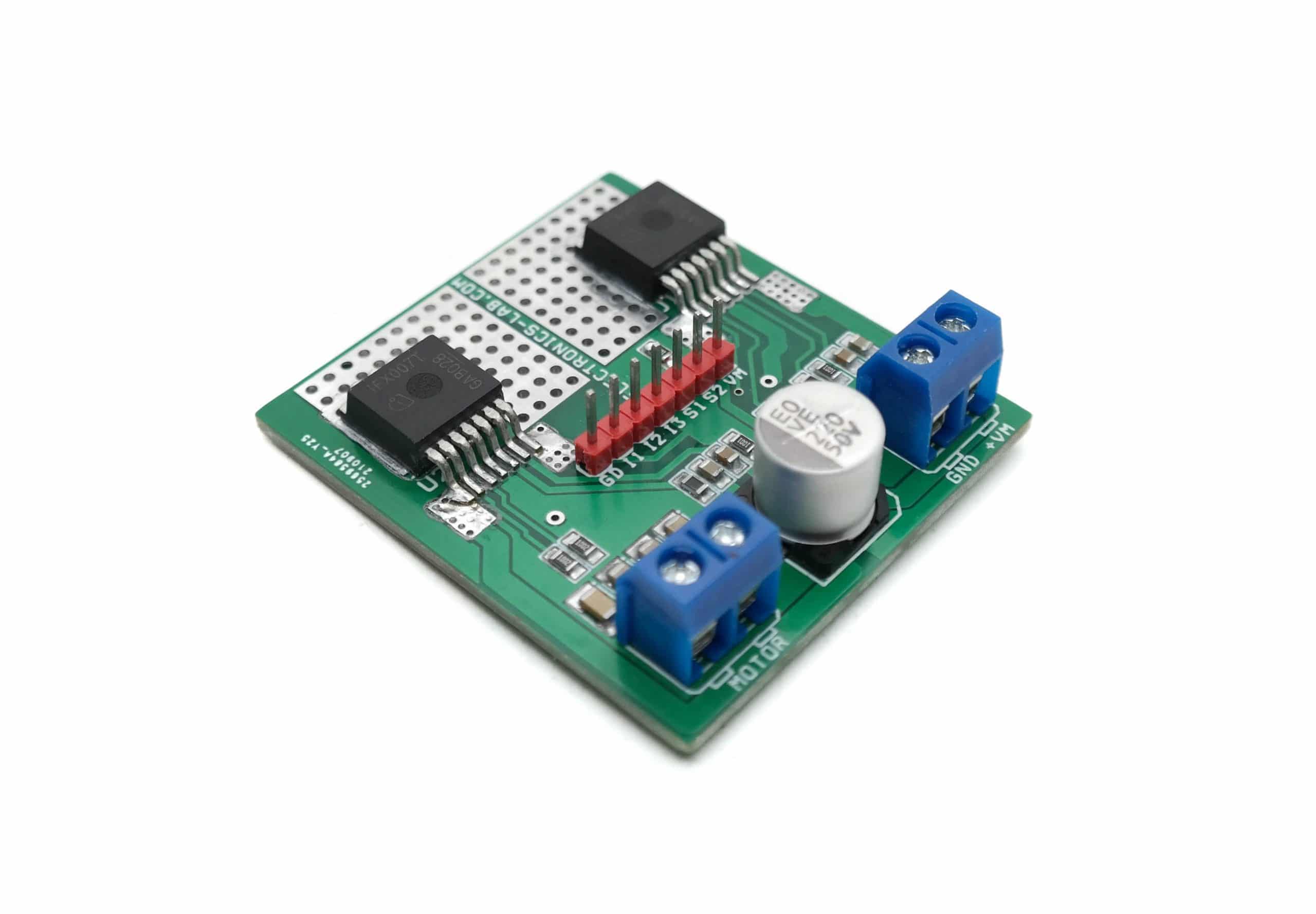
This motor driver circuit can drive a brushed DC motor with up to 250W of continuous load. The project can be controlled with the general logic IO-Ports of any microcontroller. Either an Arduino Uno or another microcontroller can be used as the control board. The project uses two IFX007T IC from Infineon. Each IC provides half-bridge operation featuring one P-channel high side MOSFET and one N-channel low side MOSFET with an integrated driver IC. The IFX007T half-bridge is easy to control by applying logic level signals to the IN and INH pin. When applying a PWM to the IN pin the current provided to the motor can be controlled with the duty cycle of the PWM. With external R6, R9 resistors connected between the SR pin and GND you can set the slew rate of the power switches. The Motor Control board can be easily connected to any Arduino board or microcontroller via headers.
Features
Brushed DC Motor Control up to 250 W continuous load
Motor Supply 8 – 24 V nominal input voltage (max. 6 – 40 V)
Average motor current 30 A restricted due to the limited power dissipation of the PCB (IFX007T current limitation @ 55 A min.)
Drives one brushed bi-directional DC motor
Capable of high-frequency PWM, e.g. 25 kHz
Adjustable slew rates for optimized EMI by changing external resistor R6, R9
Driver circuit with logic level inputs
Status flag diagnosis with current sense capability
Protection e.g. against over-temperature and overcurrent
PCB dimensions: 49.82 x 44.62 mm
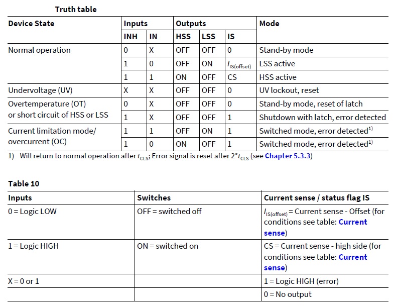
The IFX007T is an integrated high current half bridge for motor drive applications. It is part of the Industrial & Multi-Purpose Nova lithic™ family containing one p-channel high-side MOSFET and one n-channel low-side MOSFET with an integrated driver IC in one package. Due to the p-channel high-side switch the need for a charge pump is eliminated thus minimizing EMI. Interfacing to a microcontroller is made easy by the integrated driver IC which features logic level inputs, diagnosis with current sense, slew rate adjustment, dead time generation and protection against over temperature, under voltage, overcurrent and short circuit. The IFX007T provides a cost optimized solution for protected high current PWM motor drives with very low board space consumption.
We have seen during the previous tutorial that Class A amplifiers are characterized by a conduction angle of 360° and a theoretical maximum efficiency of 50 %. In this new tutorial, we will present in detail another class of amplifiers known as Class B that have been developed as an answer to the low efficiency of the Class A.
In the first section, we will present what a Class B amplification consists of and an overview of its characteristics. We will see in a later section, however, that in order to work properly, two complementary transistors are needed in order to ensure the reproduction of the input signal, in what is commonly known as a push-pull configuration. Moreover, we will highlight an undesired distortion happening in Class B amplifiers and some possible solutions to limit it. At the last section of this tutorial, we will give a step by step method on how to calculate the theoretical maximum efficiency of Class B amplifiers.
Presentation of the class B amplification
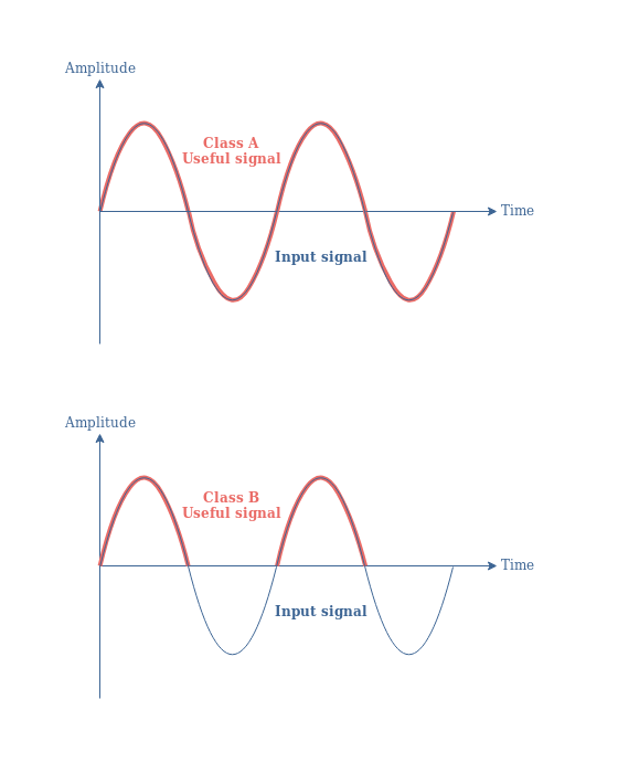
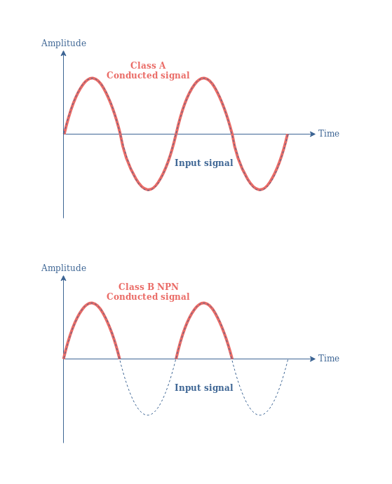
The main difference with the Class A is that Class B amplifiers have a conduction angle of 180°. This implies that only half of the input signal is processed in order to realize the amplification process. To clarify this affirmation, the Figure 1 below compares the conduction angle of a Class A and a Class B amplifiers :
fig 1 : NPN-based class A and class B amplifier conduction angle
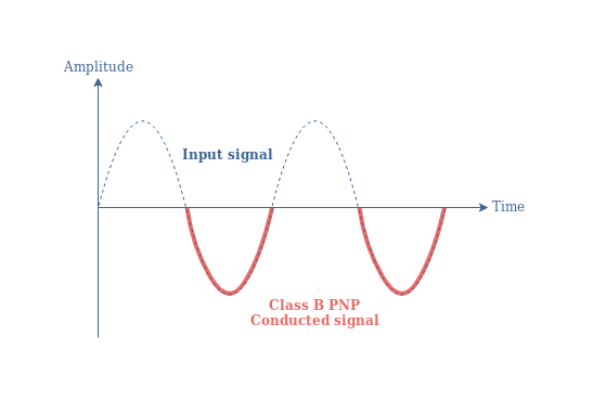
In Figure 1, we assume that the bipolar transistor (BJT) used is a NPN type. In a Class B amplifier, a PNP BJT would instead amplify only the negative parts of the signal such as shown in Figure 2 below :
fig 2 : PNP-based class B amplifier conduction angle
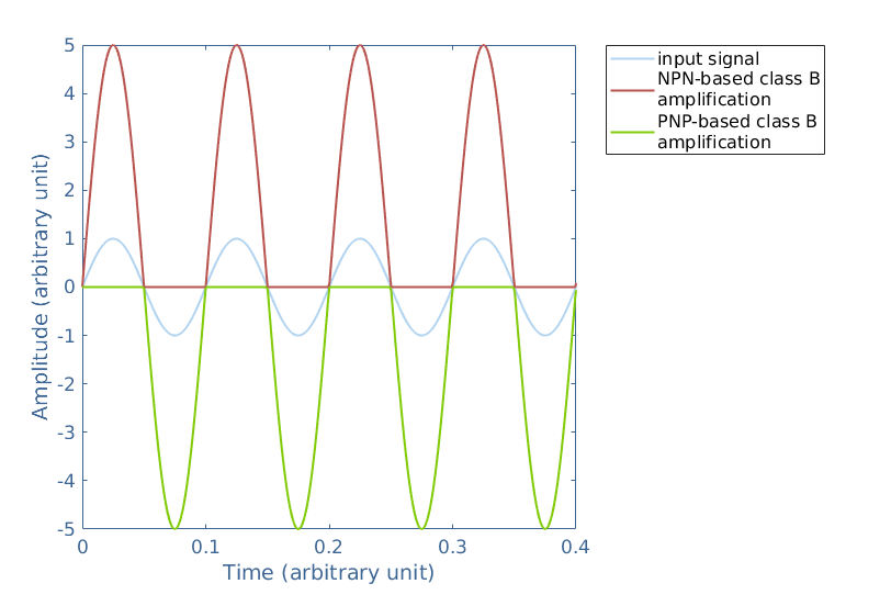
To visualize better how a Class B configuration amplifies a signal, let’s consider two transistors of signal gain 5, one NPN and one PNP. The input signal of amplitude 1 and the output signals from the NPN and PNP transistors can be plotted in the same graph in Figure 3 :
fig 3 : NPN and PNP-based class B amplification. Plotted using MatLab®
Since the NPN transistor only amplifies the positive half-wave and the PNP the negative half-wave, a faithful reproduction cannot be achieved with only one transistor. However, from Figure 3, we see that the superposition of both NPN and PNP output regenerates the shape of the input signal. In order to combine these two outputs, an NPN and a PNP transistor are placed in a so called push-pull configuration (Figure 4) that we will see in detail in the next section.
Another important characteristic of Class B amplifiers is the absence of DC bias on the base branch of the transistor. Therefore, Class B amplifiers can only conduct when the AC input signal is above the threshold level of the bipolar transistor +0.7 V. This fact plays an important role in triggering an undesired effect that is typical for Class B amplification, we will clarify this point as well in the next sections.
Push-pull configuration
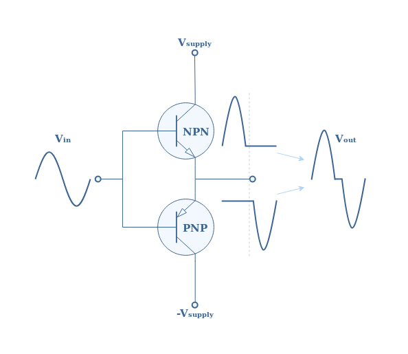
The Figure 4 below presents the output stage of an emitter-follower push-pull configuration used for the Class B amplification in addition with the input signal, outputs of the NPN and PNP transistors, and final combined output :
fig 4 : Class B push-pull configuration
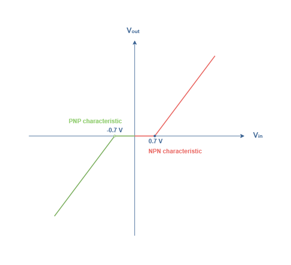
An undesired effect commonly known as crossover distortion is highlighted in Figure 4. There is indeed an interval around the zero amplitude crossover where the signal is not reproduced faithfully. To understand why this phenomenon happens specifically for class B amplifiers, we need to plot the (Vout, Vin) characteristic of the push-pull configuration :
From Figure 5, we can see that the Output/Input characteristic of a Class B push-pull configuration is only partially linear. Indeed, in a class B amplifier, the NPN and PNP transistors are working in the cutoff region, when the input signal is below the +0.7 V threshold (resp. above -0.7 V), the NPN transistor (resp. PNP) does not conduct the signal. This behavior creates an interval between -0.7 V and +0.7 V of 1.4 V where no signal can be conducted between the base and emitter branches. This explains the crossover distortion observed for Class B push-pull configurations.
Limiting the crossover distortion
The crossover distortion needs to be corrected especially for audio amplifiers where this effect is clearly perceptible. The first possible solution to limit or eliminate completely the distortion is to bias more or less the base branch depending on the desired linearity of the output signal. This solution will be detailed in the next tutorial since biasing slightly the base branch corresponds to a Class AB amplification.
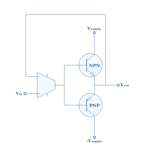
Another solution is to modify Figure 4 by adding an operational amplifier in the circuit from the output to the input such as shown in Figure 6 below :
fig 6 : Negative feedback push-pull configuration
First of all, it is important to keep in mind that an operational amplifier compares two inputs on the inverting branch (-) and the non-inverting branch (+). Operational amplifiers have a very important gain and therefore a slight difference can be highly amplified. The output of an operational amplifier (in our case the common base branch) is equal to zero only if both input signals are strictly identical.
Let’s consider that a more or less important crossover distortion can be observed at the output of a class B negative feedback push-pull configuration. When the output signal is faithfully reproduced, which is out of the [-0.7 V,+0.7 V] interval, the potential at the branch +, V+ is strictly equal to the potential at the branch -, V–. Therefore, the potential difference V+-V– is zero and no signal is amplified by the operational amplifier. The common base branch of the bipolar transistor is thus not biased.
If the output signal is in the crossover distortion interval [-0.7 V,+0.7 V], a potential difference V+-V– will appear at the operational amplifier terminals and will be amplified into the common base branch which will bias temporary the transistors in order to correct the distortion.
To summarize, we can say this circuit “forces” the output to maintain the same shape as the input, therefore, reproducing a faithful signal.
Class B efficiency
As stated during the previous tutorials, the efficiency of an amplifier is defined by the ratio η=Pout/Pabs where Pout is the output power and Pabs is the power absorbed by the transistors and the load to realize the amplification process. In the following section, we can refer to the Figure 4, having in mind that the output signal is taken on a load resistance RL.
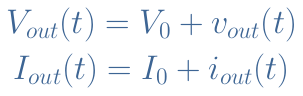
As already seen in the previous tutorial concerning Class A Amplifiers, we can decompose the output signals Vout(t) and Iout(t) such as :
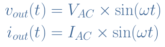
With (V0,I0) representing the biasing and (vout(t),iout(t)) the AC component. The alternative signals can also be rewritten such as :
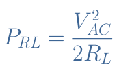
In AC regime, the dissipated power in the load PRL is expressed by the following ratio :
eq 1 : Power dissipation in the load
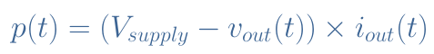
The instant power p(t) dissipated in both transistors can be written according to Equation 2 :
eq 2 : Instant dissipated power in the transistors
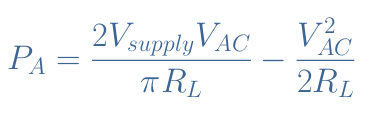
We can show through an integral calculus (that we will not detail here) that the average power PA dissipated in the transistors satisfies Equation 3 :
eq 3 : Average dissipated power in the transistors
The total power Pabs delivered by the supply is therefore simply the sum of the power dissipated in both the load and the transistors PRL+PA :
eq 4 : Power absorbed to realize the amplification process
Finally, the efficiency can be expressed by the ratio η=PRL/Pabs :
eq 5 : Efficiency of a push-pull class B configuration
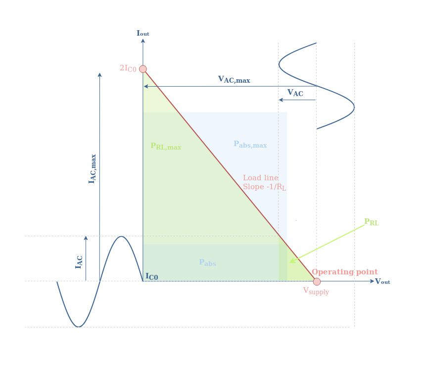
The efficiency is maximized when VAC=Vsupply, therefore giving a theoretical maximal efficiency ηmax=π/4=78.5 %. This is an important improvement of the efficiency when comparing back to the Class A amplification where only a theoretical maximum 50 % was achievable using a transformer, that in counterpart, leads to extra costs and complexity.
The above information can be summarized into a graph showing the distribution of power, presented in Figure 7. It is important to have in mind to plot this graph that VAC/RL=IAC . Moreover, to represent the quantity Pabs, we rewrite it such as Pabs=(Vsupply×√2/pi)×(IAC×√2/pi)≅((Vsupply×0.8)×(IAC×0.8).
fig 7 : Distribution of power of a class B amplifier
Conclusion
This tutorial focuses on the Class B amplifiers by presenting the characteristics of such configuration. Indeed, we have seen that Class B amplification behaves as the opposite of Class A : it presents only a 180° conduction angle and does no reproduce the signal faithfully.
Later on, it is shown that it is possible to combine two transistors NPN and PNP in order to realize a push-pull configuration that reproduces the output signal more faithfully. The NPN transistor takes care of amplifying the positive half-wave and the PNP does the similar process for the negative half-wave.
However, a crossover distortion arises from this configuration that creates a misalignment of the positive and negative half-waves in the vicinity of the zero signal zone. This phenomenon, as detailed during the same section, comes from the zero biasing applied to the common base branch of the push-pull configuration, as well as from the threshold voltages of the NPN and PNP transistors, allowing only a conductivity of the signal out of the [-0.7 V,+0.7 V] zero signal interval.
After that we focus on the possible solution to implement in order to solve the crossover distortion. One of them is to bias the base branch according to the desired level of linearity we want to achieve. This solution will be detailed much more in the next tutorial concerning Class AB Amplifiers. The second solution is to add an operational amplifier to create a negative feedback loop in the circuit. The operational amplifier forces the output signal to follow the shape of the input signal, therefore limiting or eliminating the undesired crossover distortion.
Finally, we present a method to calculate the Class B efficiency. We conclude that the theoretical maximum efficiency is 78.5 %, which is much higher than class A configurations. This increase in efficiency is due to the low 180° conduction angle that allow the transistors to only absorb power from the supply when an AC input signal is indeed present.
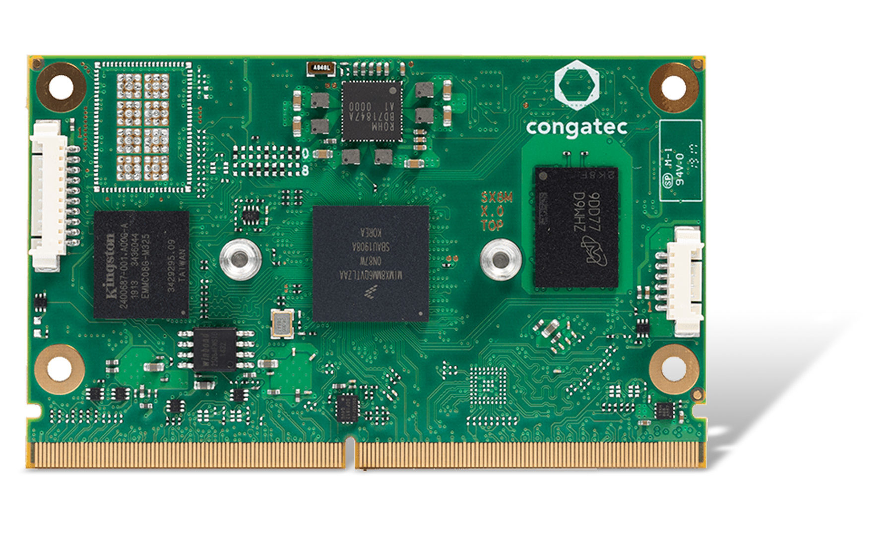
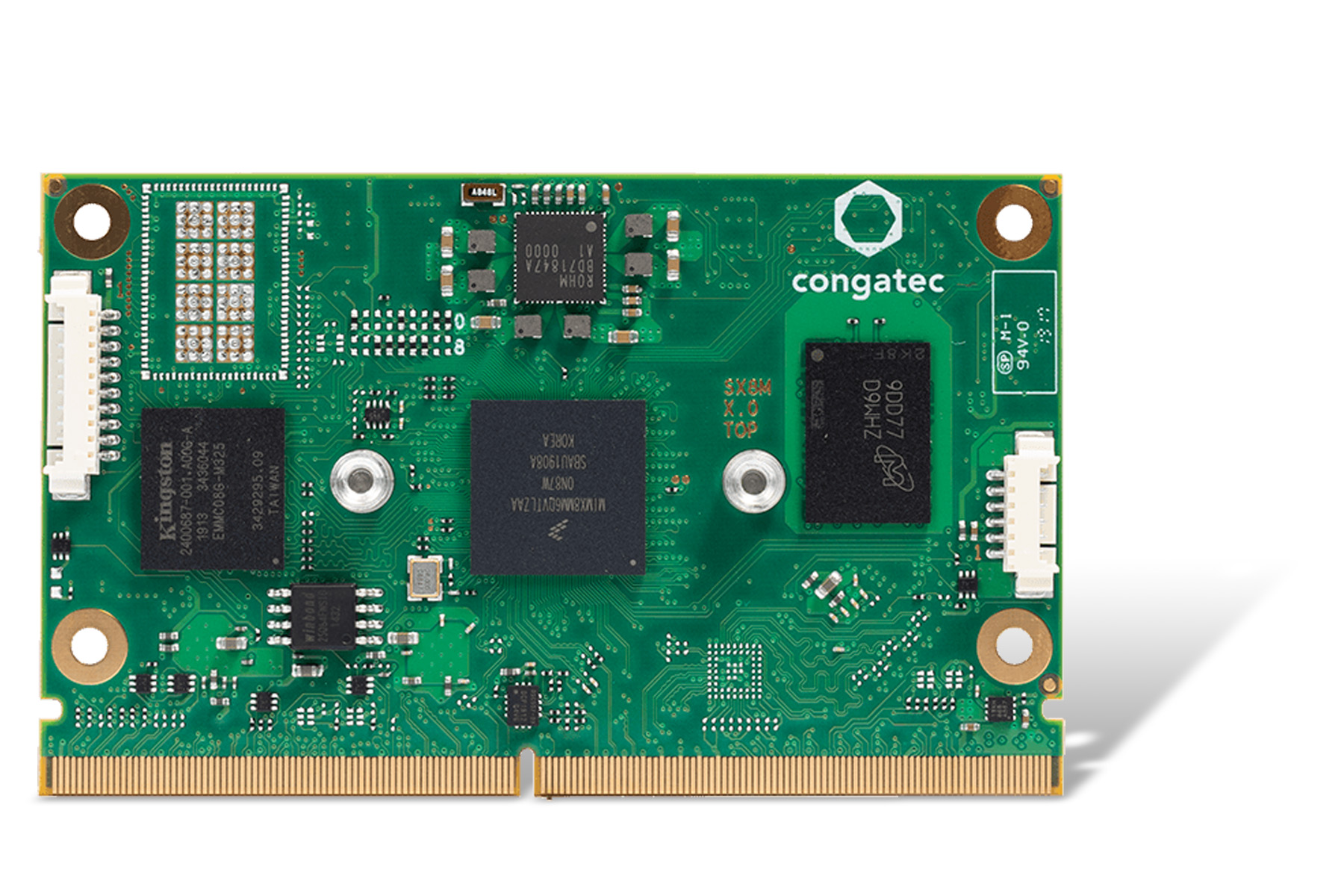
congatec – a leading vendor of standardized and customized embedded computer boards and modules – today introduces a new SMARC 2.0 Computer-on-Module with NXP i.MX 8M Mini processor. The conga-SMX8-Mini offers higher performance at significantly fewer watts¹ due to the new 14nm FinFET structure. The module also offers impressive visualization capabilities – including 3D graphics with full-HD resolution – despite low thermal and system cost. The new SMARC 2.0 platform is ideal for established markets – such as industrial and medical HMIs, kiosk, vending and infotainment systems – as well as new markets, including situational awareness, machine learning or voice controlled and video enabled residential gateway devices. For mobile and transportation applications, the new SMARC modules offer extended temperature support from -40°C to 85°C and an extended longevity of up to 15 years. Smart vision-based applications benefit from the hardware-accelerated MIPI CSI-2 camera interface.
“In addition to classic industrial controls and HMI systems that benefit from the increased 2 GHz performance, less TDP, and lower costs compared to the 1.5 GHz NXP i.MX 8M variants, the new module is also perfect for our SMARC MIPI CSI-2 starter kits, on the basis of which we can offer suitable vision camera logic in cooperation with Basler. This enables highly integrated embedded vision platforms from a single source that support the development of cost-efficient vision devices for sparse modeling based AI in the industrial and medical technology sectors, in retail checkout systems or for smart home or facility access control systems“, explains Martin Danzer, Director Product Management at congatec.
The new SMARC modules with NXP i.MX 8M Mini processor are application-ready sub systems that come with a comprehensive ecosystem including ready-to-go boot loader implementation, pre-qualified Linux, Yocto and Android BSPs and fully featured evaluation carrier boards. congatec’s personal integration support and broad range of individually selectable technical services significantly simplify the integration of this new NXP processor for customers.
Engineers have the opportunity to test the new NXP i.MX 8M Mini processor based SMARC module on evaluation carrier boards at one of the upcoming worldwide NXP Technology Days. Offering hands-on workshops and technical lectures for multiple markets, these one-day events enable attendees to customize a schedule that is most relevant to their training needs. To register for one of the events taking place in Barcelona, Bilbao, Madrid, Milan, Paris, and Boston, please visit the NXP Technology Days Website.
The feature set of the SMARC 2.0 modules
The new SMARC modules addressing ultra-low-power and price-sensitive applications feature three different quad, dual and single core ARM Cortex-A53 and Cortex-M4 based NXP i-MX 8M Mini processors, each available for the extended (0°C to +60°C) and industrial temperature range (-40°C to +85°C). The processor integrated GC NanoUltra 3D GPU convinces with comprehensive 1080p video decoding (H.265, H.264, VP8/9) and encoding (H.264, VP8) capabilities for one embedded display that can be connected via dual Channel LVDS, eDP or MIPI-DSI. Up to 4 GByte of low-power LPDDR4 and an eMMC 5.1 non-volatile memory with up to 128 GByte provide extensive memory capacity on the module. Embedded cameras are connected via the MIPI-CSI-2 interface, while 5x USB 2.0 and 3x UART are state-of-the-art for industrial use. For intersystem connect, the module offers 1x Gbit Ethernet as well as optional M2 WiFi/Bluetooth extension.
Further information on the new congatec SMARC Computer-on-Module conga-SMX8-Mini with NXP i.MX 8M Mini processor can be found at:
A team of researchers reports on a dynamically tuneable lens capable of achieving almost any complex optical function. Camera performance on mobile devices has proven to be one of the features that most end-users aim for. The importance of optical image quality improvement, and the trend to have thinner and thinner smartphones have pushed manufactures to increase the number of cameras in order to provide phones with better zoom, low-light exposure high quality photography, portraits, to name a few. But adding additional lenses to a miniaturized optical configuration and driving light focusing with an electronic device is not as easy as it seems, particularly at small scales or in such confined spaces.
The integration of an adjustable-dynamic zoom lens in a mm-thick cell phone, in a miniaturized microscope, or at the remote end of a medical endoscope requires complex lenses that can handle the full optical spectrum and be reshaped electrically within milliseconds. Until now, a class of soft materials known as liquid crystal spatial light modulators have been the tool of choice for high-resolution light shaping, but their implementation has proven to have limits in terms of performance, bulkiness and cost.
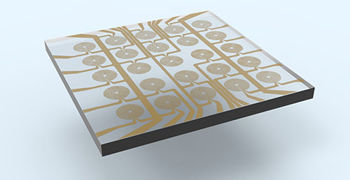
Schematic Illustration on the location with the Smartlens is placed within the optical instrument (in this case a microscope) (Image credit: Marc Montagut)
In a study recently published in Nature Photonics, fruit of a close collaboration between Pascal Berto, Chang Liu and Gilles Tessier from the Institut de la Vision, and ICFO scientists Laurent Philippet, Johann Osmond, Adeel Afridi, Marc Montagut, and Bernat Molero, led by ICREA Prof. at ICFO Romain Quidant, the researchers demonstrate an adjustable technique to manipulate light without any mechanical movement. In this approach, coined Smartlens, a current is passed through a well-optimized micrometer-scale resistor, and the heating locally changes the optical properties of the transparent polymer plate holding the resistor. In much the same way as a mirage bends light passing through hot air to create illusions of distant lakes, this microscale hot region is able to deviate light. Within milliseconds, a simple slab of polymer can be turned into a lens and back: small, micrometer-scale smartlenses heat up and cool down quickly and with minimal power consumption. They can even be fabricated in arrays, and the authors show that several objects located at very different distances can be brought into focus within the same image by activating the Smartlenses located in front of each of them, even if the scene is in colours.
By modelling the diffusion of heat and the propagation of light and using algorithms inspired by the laws of natural selection the authors show they can go way beyond simple lenses: a properly engineered resistor can shape light with a very high level of control and achieve a wide variety of optical functions. For instance, if the right resistor is imprinted on it, a piece of polymer could be activated or deactivated at will to generate a given “freeform” and correct specific defects in our eyesight, or the aberrations of an optical instrument.
As Prof. Romain Quidant points out,
“remarkably, the Smartlens technology is cost effective and scalable, and has proven to have the potential to be applied to high-end technological systems as well as simple end-user-oriented imaging devices”. The results of this study open a new window for the development of low-cost dynamically tuneable devices that could have a high impact on current existing optical systems.
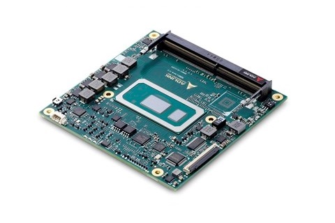
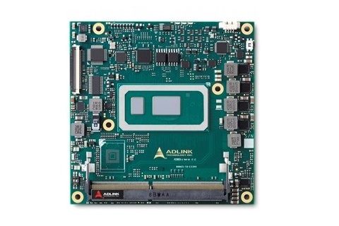
ADLINK Technology recently announced the release of its latest COM Express Compact Size Type 6 module, the cExpress-WL which follows the same path with earlier modules like the cExpress-SL and the cExpress-AL with a 95 x 95mm form factor.
The cExpress-WL features the new 8th Generation Intel® Core™ processor, the Whiskey Lake-UE (formerly “Whiskey Lake-U”) and it represents the first time an Ultra-low-power Intel Core i7 and i5 processors will support 4 cores compared to the previous generations with 2-core processors, increasing performance by almost 40% without significant increase in the price of the board.
The cExpress-WL offers standard support for Windows 10, Ubuntu LTS, and CentOS, and offers a Yocto Project based extended BSP posted on GitHub, running on the following processors:
A new critical feature is the support for USB 3.1 Gen 2 that for the first time allows for a maximum transfer speed of 10 Gbit/s, making the cExpress-WL ideally suited for transferring uncompressed UHD video streams from multiple USB cameras. The combination of USB 3.1 Gen 2 paired with a high-performance Intel® UHD Graphics, a scalable choice of processor and Intel® Distribution of OpenVINO™ Toolkit makes this module a highly flexible building block for emerging AI, machine vision and surveillance applications. More traditional applications that can benefit from the low power consumption and high performance of the cExpress-WL are medical ultrasound, test and measurement, factory automation, and industrial HMI.
The cExpress-WL features quad- and dual-core 8th Gen Intel® Core™ processors in a 15W TDP envelope and up to 64GB dual-channel non-ECC DDR4 memory, providing uncompromised performance in a compact form factor. The Intel® Gen 9 LP Graphics Core supports up to 3 independent displays with a combination of DisplayPort/HDMI/LVDS, eDP or VGA outputs to support both new and legacy applications. The module is also equipped with up to 8 PCIe lanes for system expansion.
Available wide range voltage input (5V to 20V) covers most standard applications, including outdoor scenarios such as a battery or solar-powered setups, and simplifies carrier board power design requirements. Wide-range voltage design contributes to simplified carrier power and also gives more tolerance for the power input from carrier and de-complexity of the power circuit design in carrier.
Key Features
8th Gen quad/dual-core Intel® Core™ Processors
Up to 64GB Dual Channel non-ECC DDR4 at 2133/2400MHz
Two DDI channels, one LVDS (opt. 4 lanes eDP), one opt. VGA, supports up to 3 independent displays
Up to eight PCIe lanes, GbE
Up to three SATA 6 Gb/s, four USB 3.1 Gen2 and four USB 2.0
Extreme Rugged operating temperature: -40°C to +85°C (optional)
The module comes standard with AMI Aptio V UEFI BIOS or can instead be equipped with an Intel® Slim Bootloader. Slim Bootloader is an open-source boot firmware, built from the ground up to be small, secure and optimized to run on Intel x86 architecture, and is specially designed to be small, fast and secure while also being extensible and extremely configurable for OEMs and system integrators.
Intel® Distribution of OpenVINO Toolkit lets users quickly develop applications and solutions that emulate human vision to make computer vision apps faster. It is based on convolution neural networks (CNN) and includes the popular computer vision libraries OpenCV and OpenVX. The adoption of the Intel® Distribution of OpenVINO Toolkit on the cExpress-WL allows users to fully leverage the integrated GPU’s capabilities and maximize the CPUs performance-per-watt capabilities for computer vision applications.
While no availability information was provided for the cExpress-WL, more information may be found on the product page on adlink’s website.
After the official birth of commercial EDA since 1981, different design software as been produced from the EDA industry. Printed Circuit Boards, also known as PCBs, are the foundation of any hardware-based product. Before EDA software, Engineers usually designed electronics circuitry and integrated circuits by hand or some other manual process.
There are several PCB software out there, some which are free, while others are premium. It could be a daunting task choosing from several tens of software in the market. When selecting a design package to use, it is always advisable to use some of the latest tools with available support and community. In the EDA industry, some of the best and most popular tools are mostly not free. Nevertheless, there are still a couple of powerful free ones. In this article, I will highlight some of the best free PCB design software you can find for designing your printed circuit board layout, and hopefully, this list will help you to pick what works for you.
Autodesk Eagle
1. Autodesk Eagle
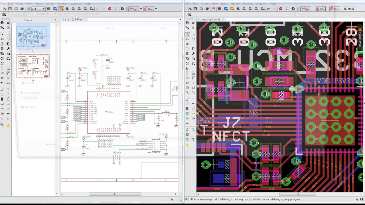
Eagle is arguably one of the most well know schematics and PCB design software. Formerly known as Cadsoft Eagle, but now called Autodesk Eagle after its purchase from Autodesk. Autodesk EAGLE contains a schematic editor, for designing circuit diagrams and a PCB layout editor for designing PCBs. It provides component placement, PCB routing, a comprehensive library content, a thriving community, and many more. A free version of Autodesk EAGLE is available called EAGLE FREE. EAGLE is now only available with a Fusion 360 subscription. It includes 2 schematic sheets, 2 signal layers, and an 80cm2 board area.
Eagle is available for Windows, Linux, and Mac. More information about Eagle is available on the product page.
KiCAD
2. KiCAD
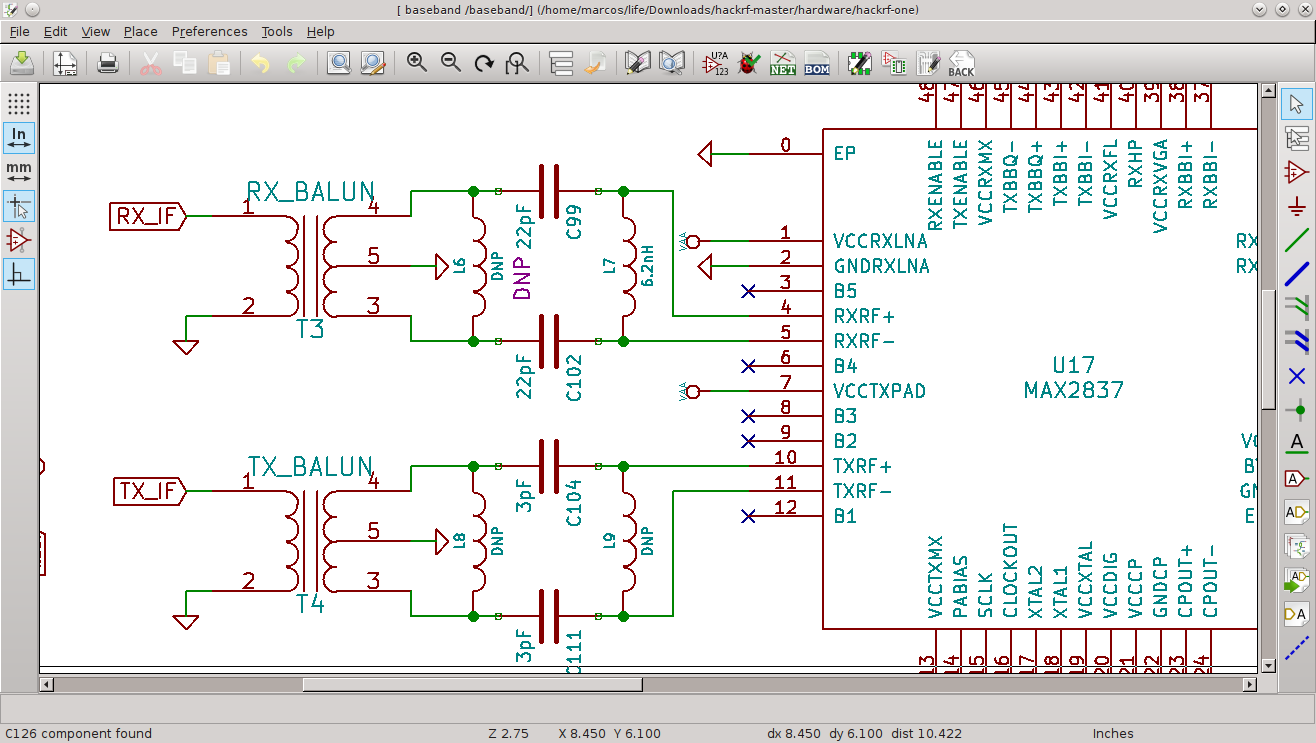
KiCAD is a Cross-Platform and Open Source Electronics Design Automation Suite. It includes a schematic editor for creating and editing schematic designs, a PCB Editor for making professional PCB layouts with up to 32 copper layers, and a 3D viewer which can be used to inspect the design in a 3D form. Unlike Eagle, KiCAD is entirely free, and no paywall is needed to use some of its features.
KiCAD is available on Windows, Linux, and Mac. More information about KiCAD is available on the product page.
Fritzing
3. Fritzing
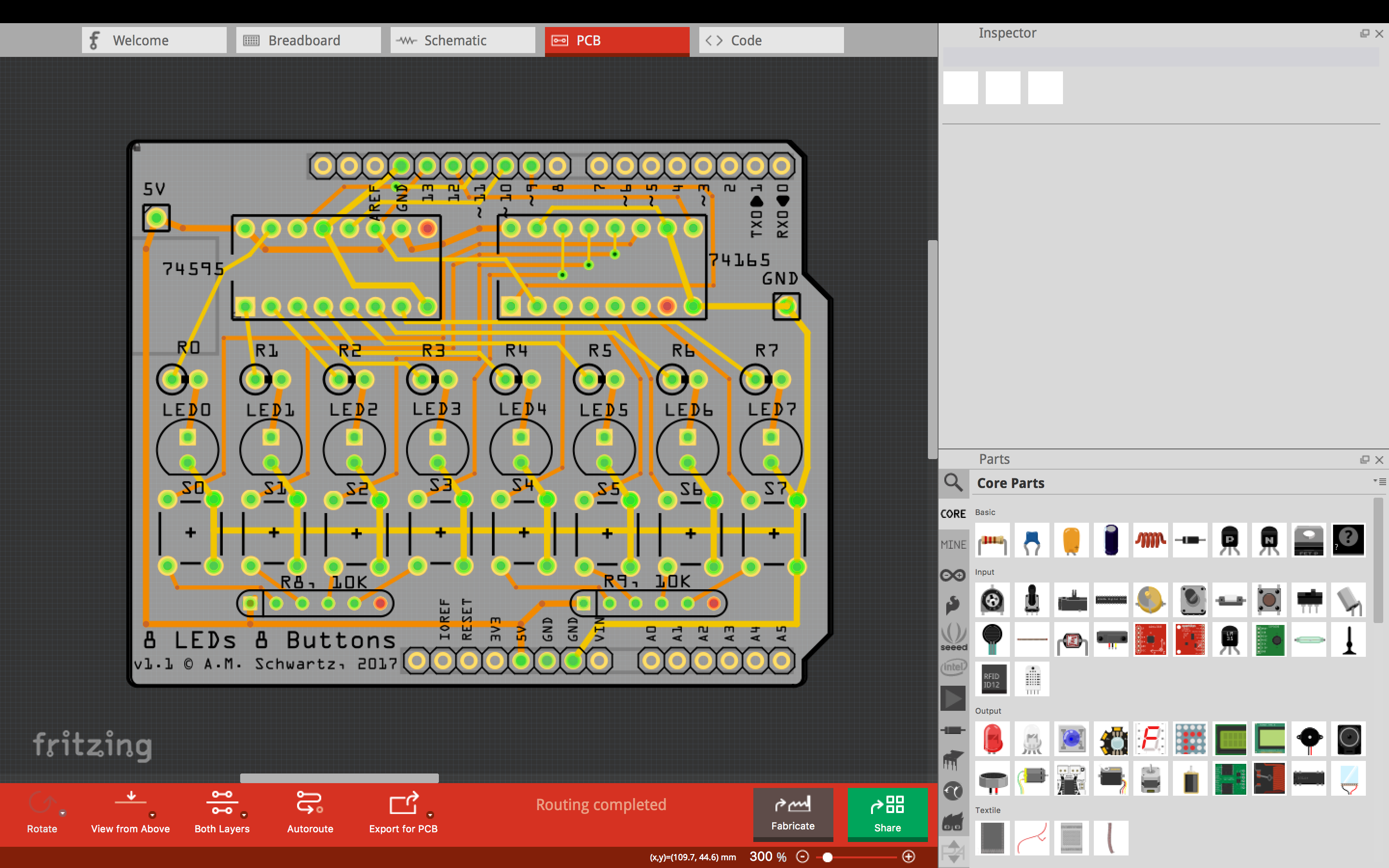
Just like KiCAD, Fritzing is an open-source platform for learning electronics. Fritzing became popular with its examples of Arduino and its an easy to use platform. Fritzing includes a breadboard layout, schematic, and PCB view for designing a PCB layout for your board. With a rich interface and growing community, fritzing is a good choice among hobbyists.
The software is available for Windows, Linux, and Mac. More information is available on the product page.
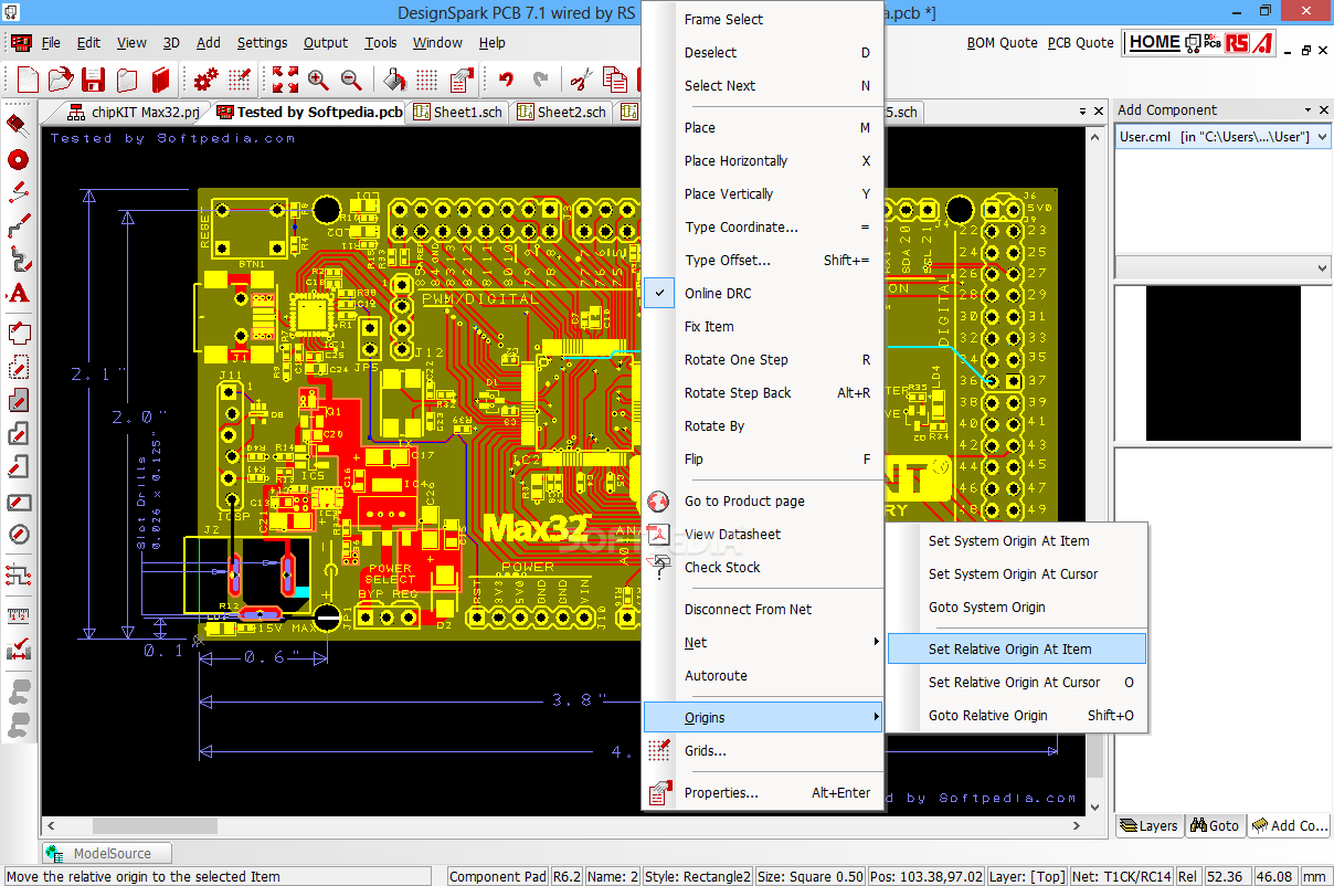
DesignSpark PCB
4. DesignSpark PCB
With an arguable easy-to-learn environment, with a schematics capture and PCB layout tool, DesignSpark PCB is one of the EDA tools to try out. It is free, comes with an excellent schematic capture, PCB editor for designing an unlimited number of PCB layers, a part and library creator, 3D views, and many more features.
DesignSpark PCB is only available for Windows. More information is available on the product page.
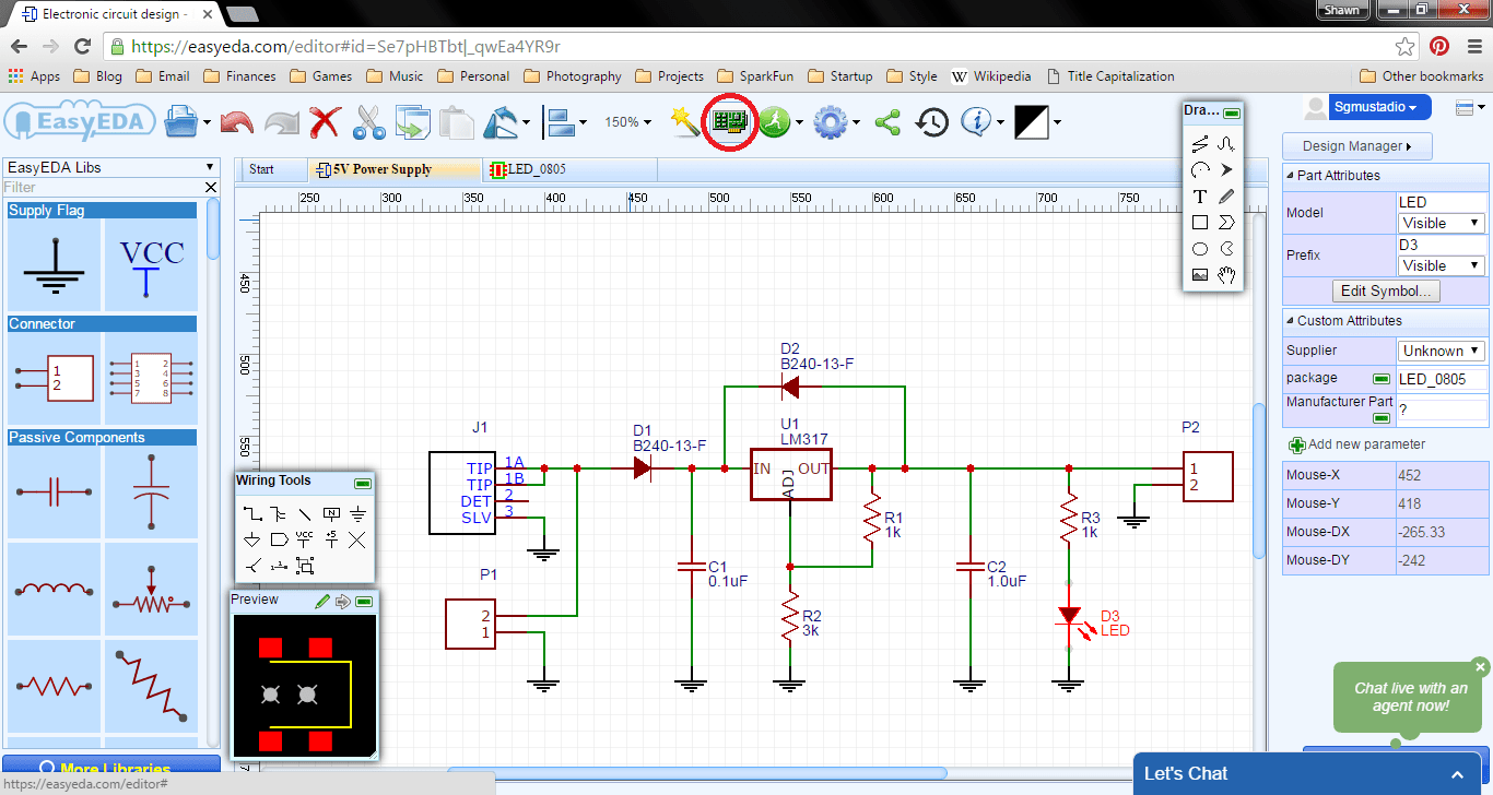
EasyEDA
5. EasyEDA
EasyEDA is a free and a paid EDA tool. EasyEDA provides a powerful schematic capture, PCB editor, Libraries designer, a project management tool, and lastly a team collaborator. EasyEDA also has an integration with LCSC.com component catalog for providing real-time stocks and pricing information about components used.
EasyEDA is online based and also desktop based. It is cross-platform and supports Windows, Linux, and Mac. More information is available on the product page.
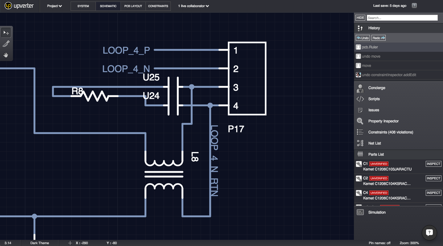
UpVerter
6. UpVerter
Upverter is a web-based EDA just like EasyEDA for enabling hardware engineers to design, share, and review schematics and PCBs (Printed Circuit Boards). It does for open-source hardware design what GitHub have done for open-source software development, providing a collaboration platform. It comes with a schematics capture, PCB editor, a system designer, 3D viewer, team collaboration, and many more. More information about the platform is available here.
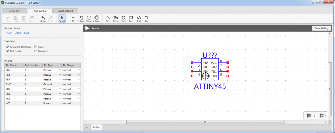
PCBWeb Designer
7. PCBWeb Designer
PCBWeb is a free CAD application for designing and manufacturing electronics hardware. It features a schematic capture for multi-sheet design, PCB layout support multi-layers, and an integrated arrow parts catalog.
PCBWeb is available only for Windows. More information is available on the platform site.
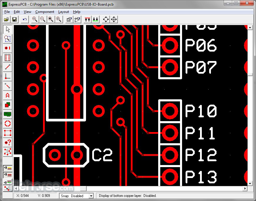
ExpressPCB Plus
8. ExpressPCB Plus
ExpressPCB Plus is an EDA software for creating and designing of electronics circuitry. It includes ExpressSCH Classicfor drawing schematics and ExpressPCB Plus for circuit board layout. ExpressPCB Plus provides the option to see the instant quotes for your PCB board and even order the board for fabrication from inside the program itself.
ExpressPCB is available for use on Windows, Linux, and Mac. More information is available on the product page.
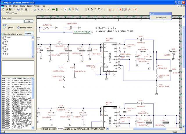
TinyCAD
9. TinyCAD
TinyCAD is a simple and basic electronic circuit schematic and PCB designer. It is an open-source software project. It supports standard and custom symbol libraries. It supports PCB layout programs with several netlist formats and can also produce SPICE simulation netlists.
TinyCAD is only available in the Windows version. More information is available on the download page.
Osmond PCB
10. Osmond PCB
Osmond PCB is an only MAC-based EDA tool. It supports schematic capture and PCB layout design. The software provides many features such as unlimited board sizes, multiple board layers, and can be used to design boards up to 700 pins.
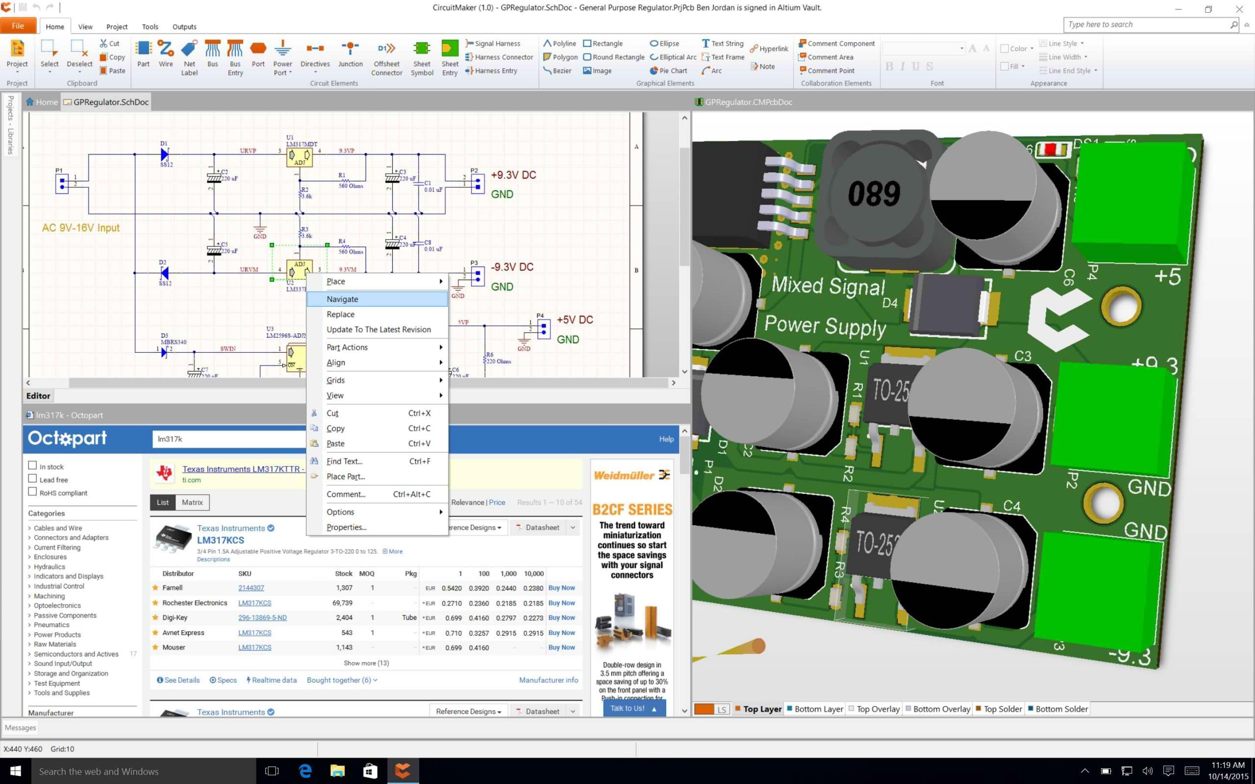
Circuitmaker is a unique combination of the broad design community, a free PCB Design software, and services, that allow everyone to work on the same premise and share the knowledge with ease. The CircuitMaker PCB Design Editor has all the power you need to design high-quality schematics and layout, with no artificial limits on layer counts or board area. CircuitMaker gives you the freedom of design with up to 16 signal + 16 plane layers and no restrictions to the PCB dimensions. You can share your project with only authors of your choice or with the entire community. Altium Native 3D™ technology means that when you’re in the PCB editor, just press the 3 key and you can immediately see the PCB layout in full 3D. It seems one of the most complete PCB design software that is available for free.
Feel free to share your own favorite EDA tool or suggest what you think might be better on this list. If you are interested in learning how to make your first printed circuit board, then tread the “Making Your First Printed Circuit Board.”
NXP Semiconductors i.MX RT106A Crossover Processor is a solution specific variant of the i.MX RT1060 family of MCUs, targeting cloud-based embedded voice applications. It features NXP’s advanced implementation of the Arm® Cortex®-M7 core, which operates at speeds up to 600MHz to provide high CPU performance and best real-time response. i.MX RT106A based solutions enable system designers to easily add voice control capabilities to a wide variety of smart appliances, smart home, smart retail, and smart industry devices.
The i.MX RT106A is licensed to run NXP turnkey voice-assistant software solutions, which may include:
Far-field audio front-end softDSP
Acoustic echo cancellation
Ambient noise reduction
Beamforming
Barge-in
Playback processing
Codecs
Wake-word inference engine
Media player / streamer
MQTT, lwIP, TLS
Discovery and onboarding
All drivers, including Wi-Fi® and Bluetooth™
The i.MX RT106A is offered in a 196-ball Molded Array Process Ball Grid Array (MAPBGA) package, with a 0°C to +95°C consumer-grade temperature range.
Features
High-performing Arm Cortex-M7
3020 CoreMark/1284 DMIPS @ 600MHz
1MB On-Chip SRAM – up to 512KB configurable as Tightly Coupled Memory (TCM)
Real-time, low-latency response as low as 20ns
Low dynamic power with an integrated DC-DC converter
Low-power run modes at 24MHz
Advanced multimedia for GUI and enhanced HMI
2D graphics acceleration engine
Parallel camera sensor interface
LCD display controller (up to WXGA 1366×768)
3x I2S for high-performance, multi-channel audio
Extensive external memory interface options
NAND, eMMC, QuadSPI NOR Flash, and Parallel NOR Flash
Wireless connectivity
Wi-Fi, Bluetooth, Bluetooth Low Energy, ZigBee, and Thread
Supported by MCUXpresso SDK, IDE and Config Tools
Package
Type: MAPBGA-196
Dimensions: 10mm x 10mm, 0.65mm pitch
Applications
Consumer electronics
Home appliances system control
In-home display
Room air-conditioning system
Smart-connected appliances
Secure transaction and retail payments
Bluetooth beacons
Electronic shelf labels
Post terminals
Home and building control
Alarm and access panels
Garage door openers
Gateways
Smart lighting
Smart plugs / outlets
Industrial
Programmable Logic Controller (PLC)
Datasheets
The NXP Semiconductors i.MX RT106A Crossover Processor is covered by the same same specifications as the i.MX RT1060 MCUs described in the i.MX RT1060 Datasheet, with the exceptions outlined in the i.MX RT106A Datasheet Supplement. The i.MX RT106A uses the same Reference Manual as the other i.MX RT1060 family members.
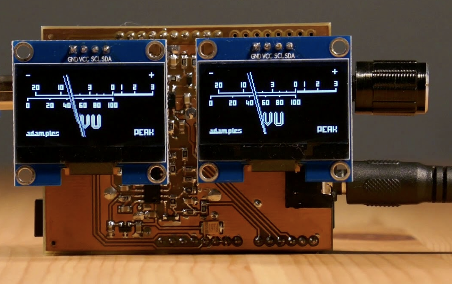
Today we are going to build one of the most important tools in sound mixing; A audio VU (volume unit) meter based on an Arduino/AVR microcontroller. This project serves to demonstrate how the knowledge of electronics can be applied to build solutions for any part of your day to day life.
Arduino VU Meter
A volume unit (VU) meter or standard volume indicator (SVI) as it’s sometimes called, is a device which displays the audio signal level of an audio signal. It is essentially a basic voltmeter (fitted with transducers to convert sound to voltage) that takes a simple average of the signal and displays it with an attack and release time of around 300 ms. It was originally designed as a kind of loudness meter, rather than as a peak meter, but it is generally used in audio recording to help make sure you’re recording at appropriate levels.
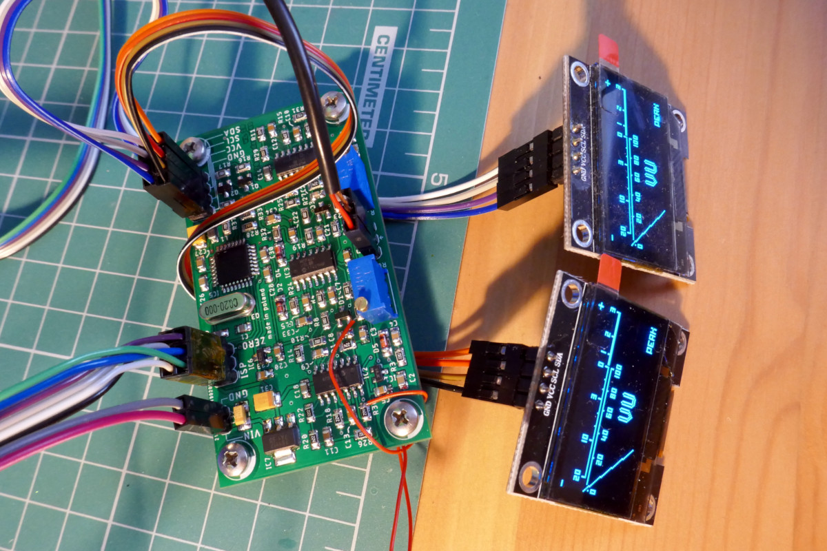
Today’s version of the project is based on a project started by Adam Ples on Github and it uses AVR ATMega88/168/328 (and ATMega48 if possible) which makes it compatible with Arduino boards like the Uno, Nano and Due. For the display, the project was designed to be compatible with small (and cheap) monochrome OLED displays based on the SSD1306 or SH1106 driver.
The goal of this version of VU meter include:
To achieve a 2-channel operation,
Accuracy to be as close to real VU-meter specification as possible,
high FPS, 60+ — no visible jumping of the needle, as is common in other designs.
How it Works
A simple block diagram shows how the project works:
Due to the attention to detail, and the desire to ensure it comes as close as possible to the standard of commercial VU meters, the project comprises of a slightly complex analog front end. More complex than most of the other VU based tutorials you may find on the internet but totally worth it if quality and accuracy is a goal for you.
The analog front end takes the audio signal and passes it through a rectifier block after which the signal is passed through the ballistics block which is configured to meet the very specific ballistic characteristics of VU meters. The signal is then fed into the ADC of a microcontroller which then transforms it into data to be displayed on the OLED.
Required Components/BOM
Due to the complexity of the design, replicating it on a breadboard will be difficult for the most hobbyists as such the project will be built on a PCB and the components used were optimized for that purpose. For example rather than use through-hole components, SMD Components were used. A BOM will be made available under the download section but here is a detailed list of the components used;
Part Name
Technology
Package
Value
Add. Params
Quantity
Resistors
Thin film
0805
10k
1%
15
Thick film
0805
220R
2
1k
2
22k
2
47k
2
82k
2
220k
10
Trimmer
3296W
10k
2
Capacitors
Ceramic
0805
22pF
2
33pF
2
220pF
4
47nF
2
100nF
10
220nF
2
330nF
4
470nF
2
1uF
2
10uF
1
Tantalum
1210
10uF
16V
1
100uF
6.3V
2
Diodes
SOD80
1N4148
2
BAT85
2
SOT23
BAS70-04
2
Transistors
SOT23
BSS138
2
Integrated Circuits
linear regulator
SOT223
1117-5.0
1
SOT23
MCP1700*33
1
SOT23
MCP1525
1
Op-amp
SO14
MCP604
1
MCP6004
2
Microcontroller
TQFP32
ATmega88P
1
Others
Crystal resonator
HC49/S
20MHz
1
Choke
1210
10uH
1
Pin headers
1×2
1
1×3
1
2×3
1
2×4
1
These components are readily available and can be bought from most electronic component stores.
Schematics
To make the project easy to use, the VU meter was designed to come either as a standalone module or as a shield, pin-compatible, and to be plugged on boards like the Arduino Uno. As mentioned earlier the complexity of the project makes it a tedious task to implement on breadboards, as such, both the schematics and the PCB design will be shared under this section and also attached in the zip file under the download section. The Schematics and PCB were developed with Eagle, so you should be able to modify as you want.
Standalone module Schematics and PCB
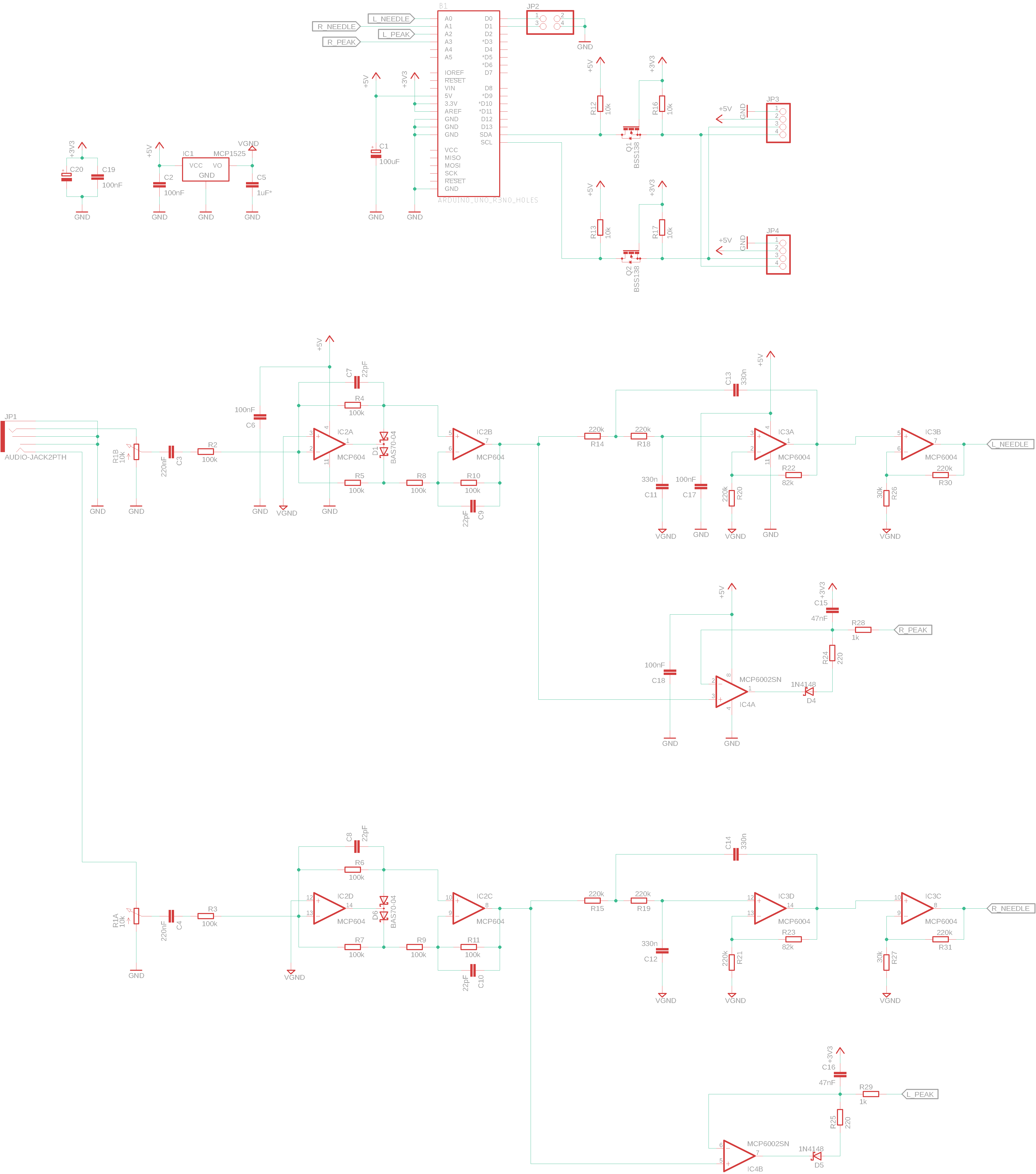
The schematics for the module is shown in the image below. The schematic is quite large, as such, you might need to zoom in to properly see how the components are connected.
Module Schematics
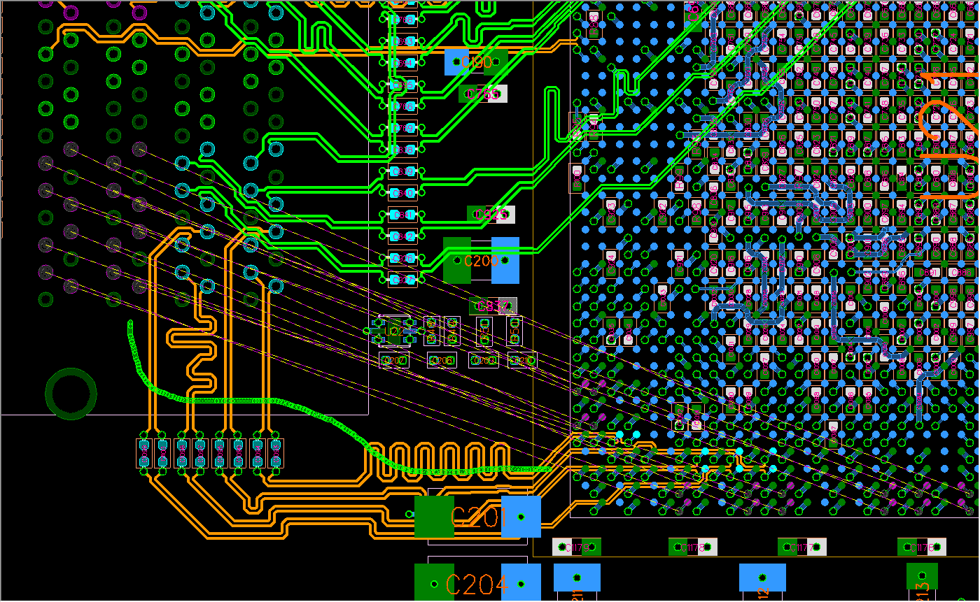
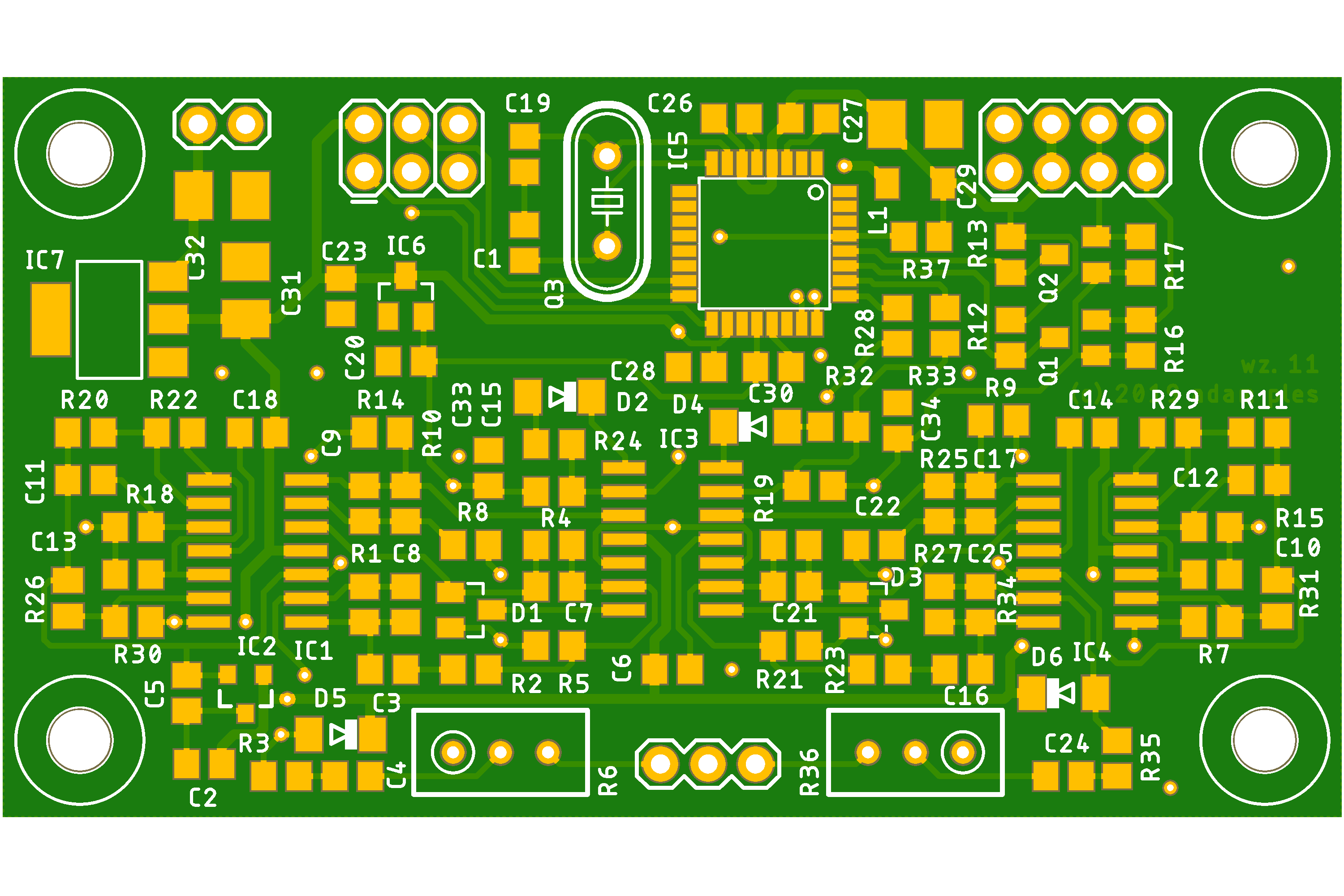
The image below represents the PCB of the VU meter after all the components have been placed. The PCB file is attached under the download section, feel free to edit and make changes in the arrangement as you desire.
PCB of VU meter
VU-Meter Shield for Arduino
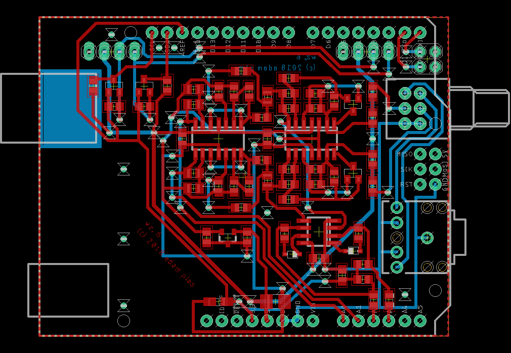
The VU meter shield is designed to run off the Arduino Uno and should work with other Uno Compatible board. The schematics for the shield is shown in the image below.
VU Meter Shield for Arduino
Transforming the schematics to PCB, we get the image below.
Software
The source code for the project is provided in the .src file under the download section. To flash your board with the code, you will have to build the .hex file from the files in the source folder and flash your board with it.
To build a hex file from the source code, you will need the following tools:
Avr-GCC
GNU make
Python 2.7 or 3
For windows users, you can use this distribution of GCC and make: http://blog.zakkemble.co.uk/avr-gcc-builds/. Before compilation, ensure you take a look at all the files in the src folder as there might be one or two that may require modification to tailor the project to your specific needs. For instance, the Config.h file under the source folder (src/config.h) houses configurations for the project and you may need to modify it and do things like changing the OLED controller type to match your own OLED. You may also need to modify the content of the Makefile to set the microcontroller you are using and the oscillator frequency (F_CPU).
To create the hex file type
With your Avr-GCC and other tools installed, open a terminal (or command prompt) on your PC, change directory to the folder containing all the project files including the “src” using the “cd command” then run the make command to create the hex file;
$ make all
This will create a main.hex file under the build folder. This hex file can then be used to flash your device.
While flashing the module version of the VU meter with the hex file may be quite easily achieved courtesy of tools like the Atmel Studio, the case is quite different for the shield, as flashing an Arduino board with a hex file gets a bit tricky since the feature is not a part of the Arduino IDE.
To solve this and flash the Arduino board with the .hex file, we will use a tool called xLoader. The xLoader is a simple tool that allows you easily flash your Arduino board with hex files. It has a simple user interface that allows you to select the file, set the COM port and BAUD RATE, and just hit upload. The only downside to this tool is it’s only available for Windows PCs.
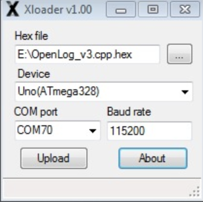
Download and install the xLoader from the attached link, then connect your Arduino board to the computer, select the .hex file we generated as shown below, set the baud rate and comport to match that of your Arduino, and hit upload.
Flashing with hex file using xLoader
The same process can be used to flash the Module version of the VU meter with the hex file.
Demo
With the code uploaded, plug in an audio source into one or both audio channels. You should see the needle on the VU meter deflect in tune with the volume property of the audio source.
Arduino shield Demo
The same thing for the module. After flashing it with the .hex file, connect some sound to it, you should see the needle move accordingly.
Standalone module Demo
That’s it for this tutorial. As mentioned above one of the goals of this tutorial was to show you how tools you use every day can be replicated using electronic components that make it way cheaper and useful.
What other tools will you be making? Feel free to reach out to me via the comment section with questions and experiences that you feel could benefit everyone.
You can watch the video version of the demo by Adam Ples.
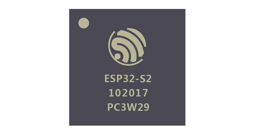
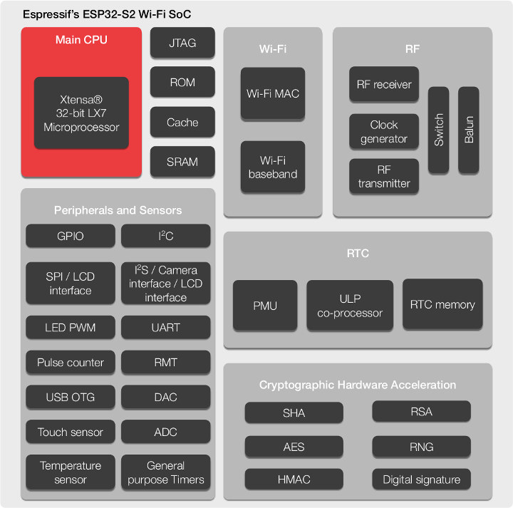
Since the launch of the ESP-01, the ESP series of WiFi modules and WiFi-enabled microcontrollers have endeared themselves to the heart of both hobbyist and electronics design professionals. They have been used for all sorts of projects and while users are still praising the impressive features built into its most recent version, the ESP-32, Espressif systems have announced details of the next one which is the ESP32-s2.
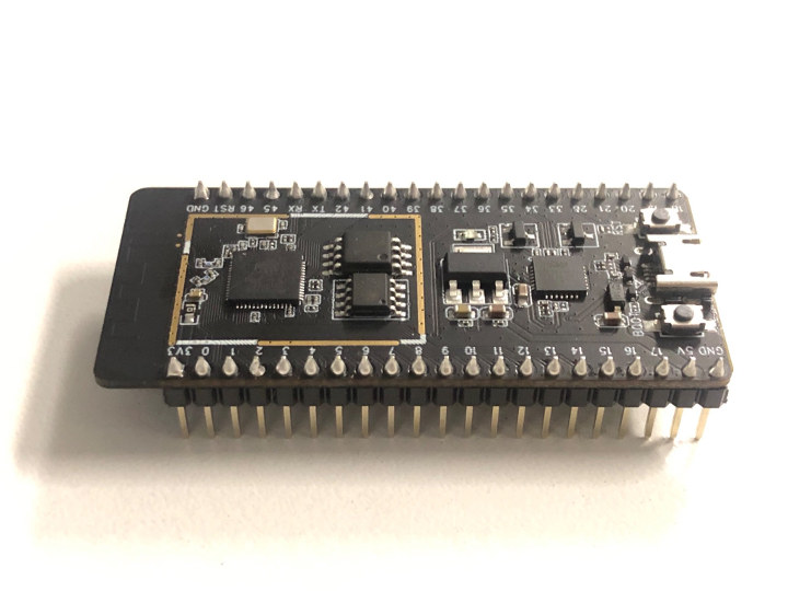
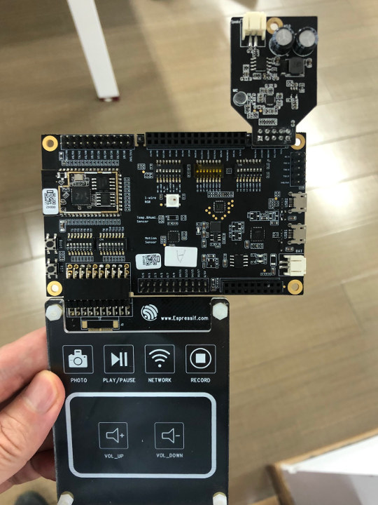
The New ESP32-S2 Based Development Board
The ESP32-S2 incorporates a Wi-Fi subsystem that integrates a Wi-Fi MAC, Wi-Fi radio and baseband, RF switch, RF balun, power amplifier, low noise amplifier (LNA) among others, with an Xtensa single-core 32-bit LX7 microprocessor clocked at 240 MHz making it useful for WiFi-based solutions without the need for an additional microcontroller. It is an highly-integrated, Low-power, 2.4 GHz WiFi system-on-chip solution. It is an ideal choice for a wide variety of application scenarios relating to wearable electronics, smart home and Internet of Things (IoT) and the ESP32-S2 unlike other ESP processors launched so far, is the first of its kind to come with an in-built USB (OTG) interface, advanced peripheral interfaces, WiFi Time-of-Flight, and hardware security features.
The on-chip memory aboard the ESP32-S2 includes 128 KB ROM, 320 KB SRAM, 16 KB SRAM in RTC and SPI/QSPI/OSPI that supports multiple flash/SRAM chips. It also has various dedicated security features like the Cryptographic hardware accelerators (integrated for RSA and AES algorithms), the Random Number Generator (RNG), flash encryption, secure boot, HMAC, digital signature as well as 4096-bit OTP up to 1792 bits for users.
Some advanced peripheral interfaces of this device include:
43 × programmable GPIOs
2 × 12-bit SAR ADCs, up to 20 channels
2 × 8-bit DAC
14 × touch sensing IOs
4 × SPI
1 × I2S
2 × I2C
2 × UART
RMT (TX/RX)
LED PWM, up to 8 channels
1 × full-speed USB OTG
1 × temperature sensor
1 × DVP 8/16 camera interface, implemented using the hardware resources of I2S
1 × LCD interface (8-bit parallel RGB/8080/6800), implemented using the hardware resources of SPI2
1 × LCD interface (8/16/24-bit-parallel), implemented using the hardware resources of I2S
There is a favorable trade-off between the power consumption, communication range and data rate of the processor as a result it features fine-grained clock gating, adjustable power amplifier output, and the dynamic frequency and voltage scaling.
Like it’s predecessors there is also a development board based on the ESP32-S2 processor and it has 21-pin I/O headers for expansion, power signal, and rest pins. There also seems to be an SPI flash on the board along with an SPI RAM.
While it may take a while before the boards become publicly available as there is no reference to it in the Espressif documentation website and in the ESP-IDF source code, the first ESP32-S2 development boards are available at Espressif Systems’ offices.
Asides the development boards, Espressif Systems also has full-featured evaluation kits with audio expansion boards and touch buttons for those interested in doing more development with the processor.
Though not available yet (samples of the ESP32-S2 will be available in June 2019), the ESP32-S2 processor has seen some recent development in the past few weeks. You can check out ESP32-S2 announcement for the specs of the released datasheet and the development boards which are also available in the Espressif Systems’ offices.
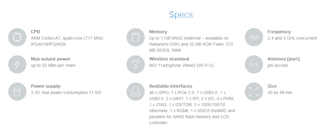
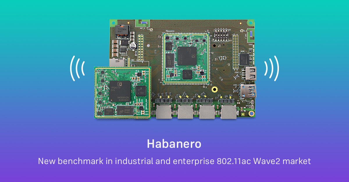
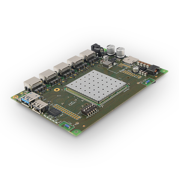
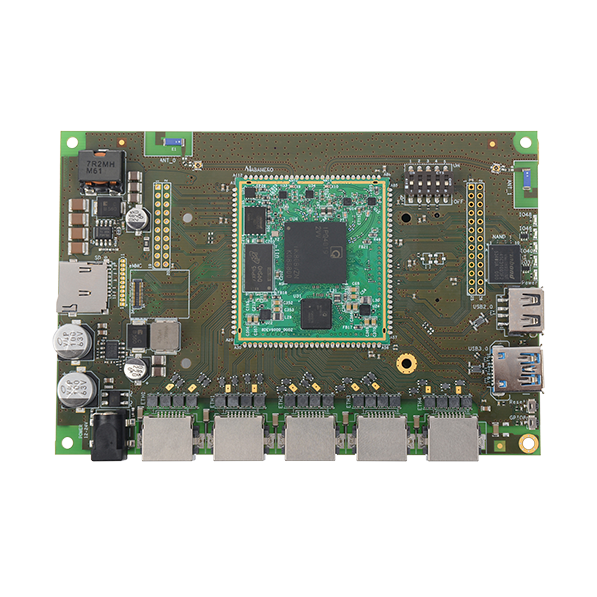
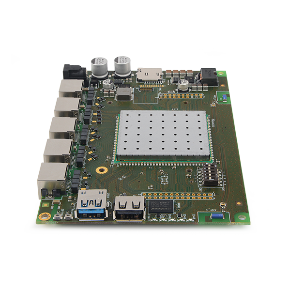
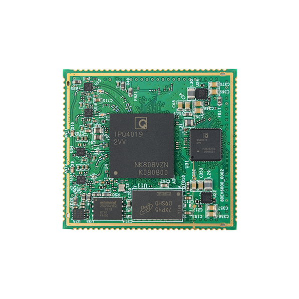
Habanero (-I) is an ultra-fast and interface rich 802.11ac Wave2 SOM with industrial temperature range support.
Habanero system on module (SOM) is based on an IPQ4019/IPQ4029 SoC from Qualcomm, which incorporates a powerful quad-core ARM Cortex A7 processor with NEON and FPU. It is ideal for resource demanding applications including routers, gateways and access points. Habanero comes with a high-power, dual-band concurrent radio supporting 802.11ac Wave2 technology (2×2 MiMo). QCA8075C PHY gives support to 5 x Gigabit Ethernet ports. It also has 1 x USB3.0 and 1 x USB2.0 ports and supports other miscellaneous interfaces, which can be configured as general-purpose I/O pins. Hardware based NAT engine and security features like crypto engine, secure boot make it ideal for high-end, fast and secure networking applications. Habanero comes in commercial and industrial temperature versions. Commercial temperature range: 0-65°C, industrial temperature range: -40-85°C.