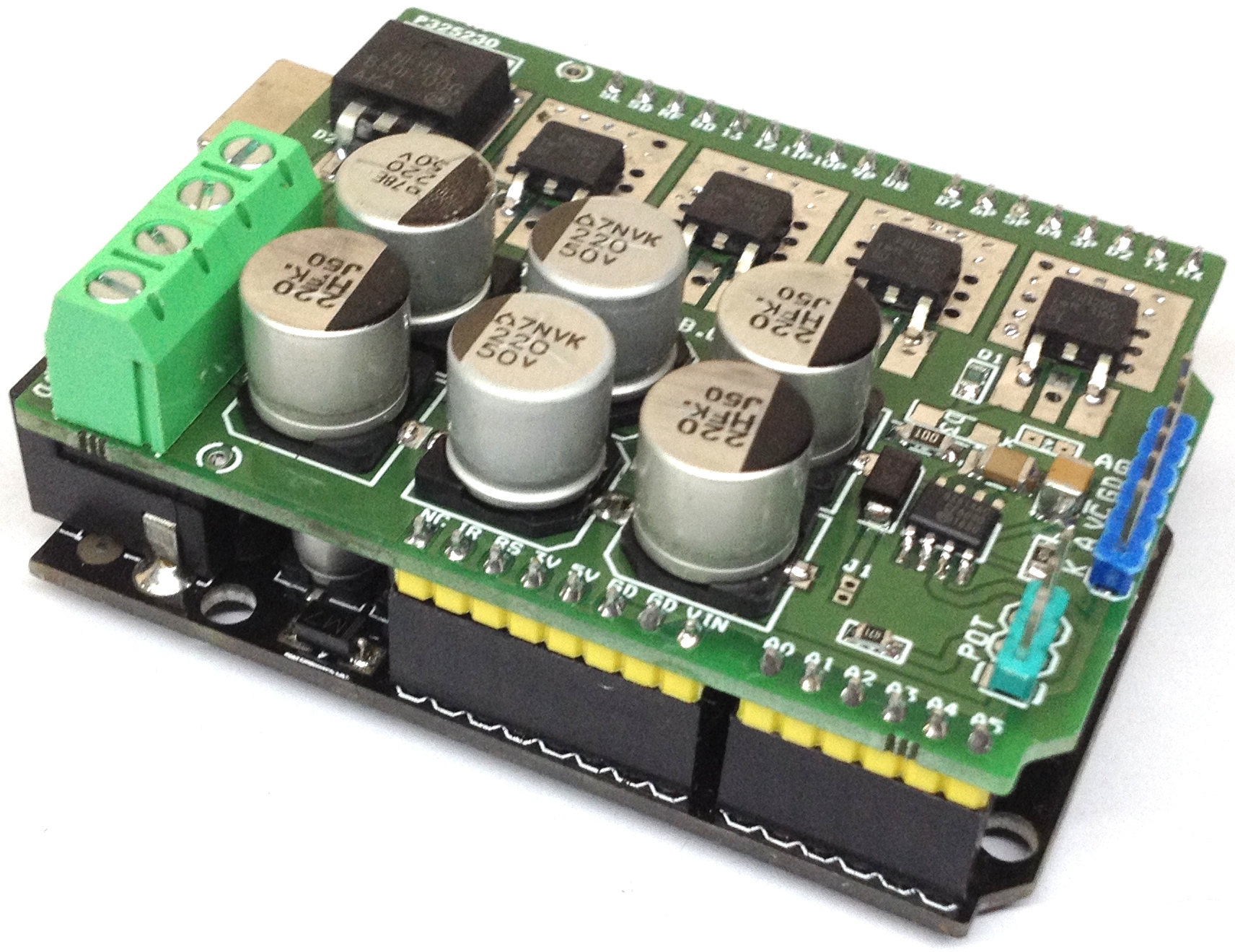
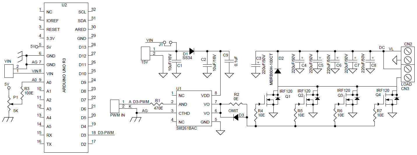
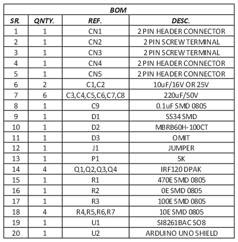
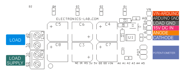
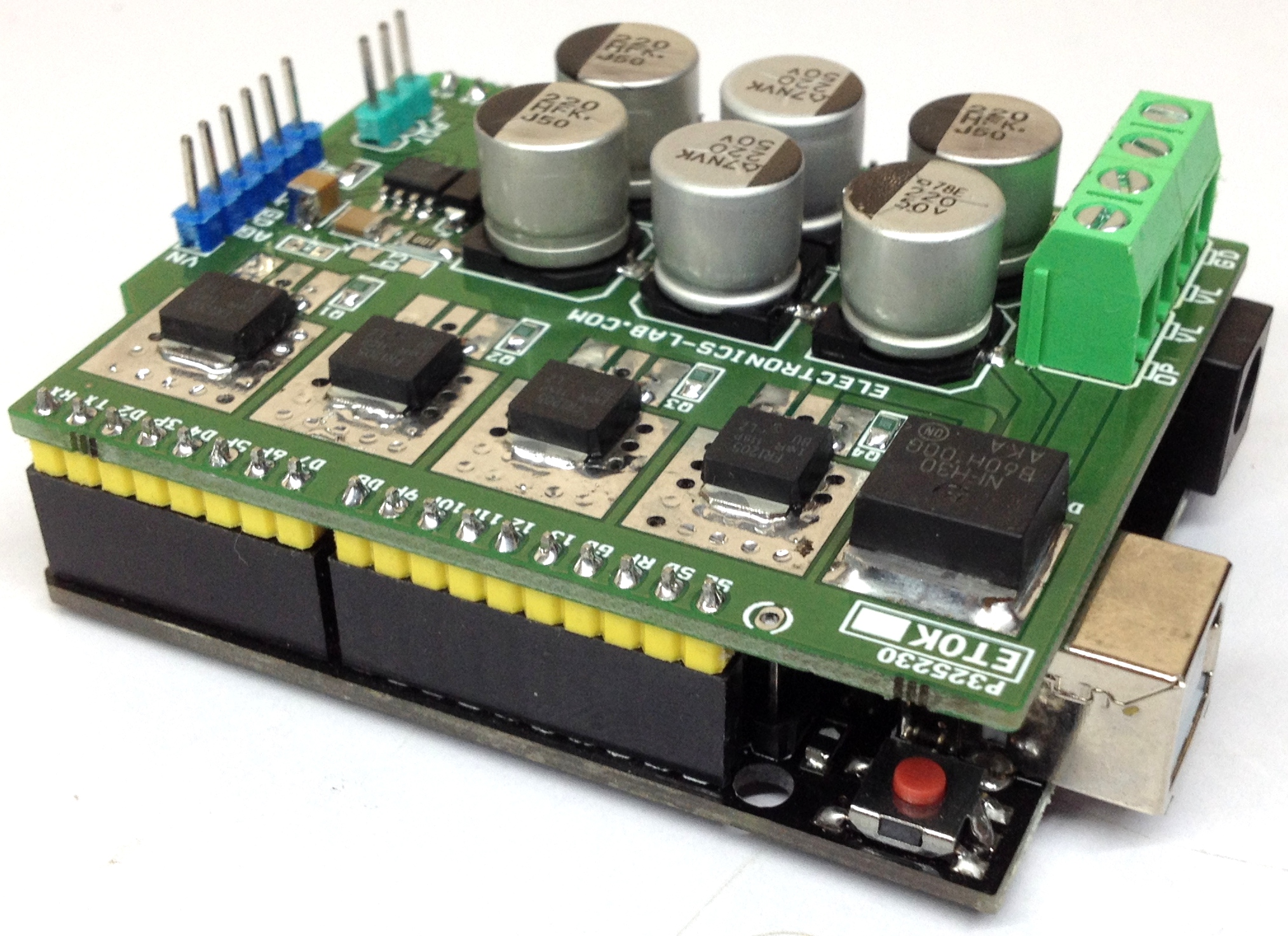
Isolated high power Mosfet DC solid state relay shield allows you to control high current DC load in switching or PWM control mode. The project can be used in wide verity of applications like DC-DC Converters, inverters, DC motor control, solenoid, LED Dimmer, battery chargers and it can control inductive and resistive loads. On board high current fast recovery diode across the load provided for back EMF protection. The board can control load up to 25A with input supply up to 48V DC. High voltage DC input supply up to 90V is possible by altering DC bus capacitor voltage. Input PWM frequency up to 100 KHz duty cycle 0-100%. Mosfet power driver is isolated from Gate driver input. Gate driver circuitry requires 15V DC. Load supply 15V to 48V DC. Jumper J1 helps to use common supply for Arduino and gate driver. Screw terminal CN3 helps to connect load supply and load. Anode of gate driver connected to D3-PWM pin of Arduino to feed PWM signal or ON/OFF. P1 Potentiometer connected to Analog pin A0 of Arduino to adjust the PWM. Higher current Mosfets can be used to get more output current. Gate input requires TTL level signal.
Isolated High Power DC Solid-State Relay Shield for Arduino – [Link]
I think we all have been there – “How do I power my Pi?”
One of the concerns that come with working with the Raspberry Pi is a power supply. As you begin to use your Raspberry Pi to create complex projects, the burden of supplying a portable power supply to it becomes more. With super powerful processing capabilities which makes it useful for everyday computing and sometimes as the brain behind most systems and standalone projects, The Pi is a very useful Single Board Computer (SBC) that is very good at what it does but isn’t exactly the easiest thing to supply power to. To help users get over this power constraint, the Omzlo’s PiVoyager was created.
PIVoyager
The Omzlo’s PiVoyager was designed to make powering the pi less complicated and less stringent. The UPS product from the NoCAN IoT Platform team, when compared with other UPS HaT like the PiJuice Zero, is much lower in price and serves at a relatively higher capacity.
While it is fully compatible with Pi Zero form factor because of the way it is shaped (Pi Zero HaT), it can conveniently work well with any Raspberry Pi with the general 40-pin header in the Pi 2, 3, B+ and 4.
The UPS Hat is a special one with a real-time calendar clock that stores the current date and time while using it with your Raspberry. It comes with a programmable watchdog that powers the Raspberry Pi when it becomes inactive and a wake-up/alarm feature that powers up the Pi at a specific date and time, which could be a very useful feature for certain projects.
Some of the other features of the PiVoyager includes;
Monitoring the battery voltage and the power status of your Pi
it powers up the Pi after a certain delay and forces it to shut down entirely after a certain specified delay.
A built-in bootloader to update the firmware through 12C and a battery connector with an alternative 2-pin header of 2.54mm for connection.
Indicators to show operational status
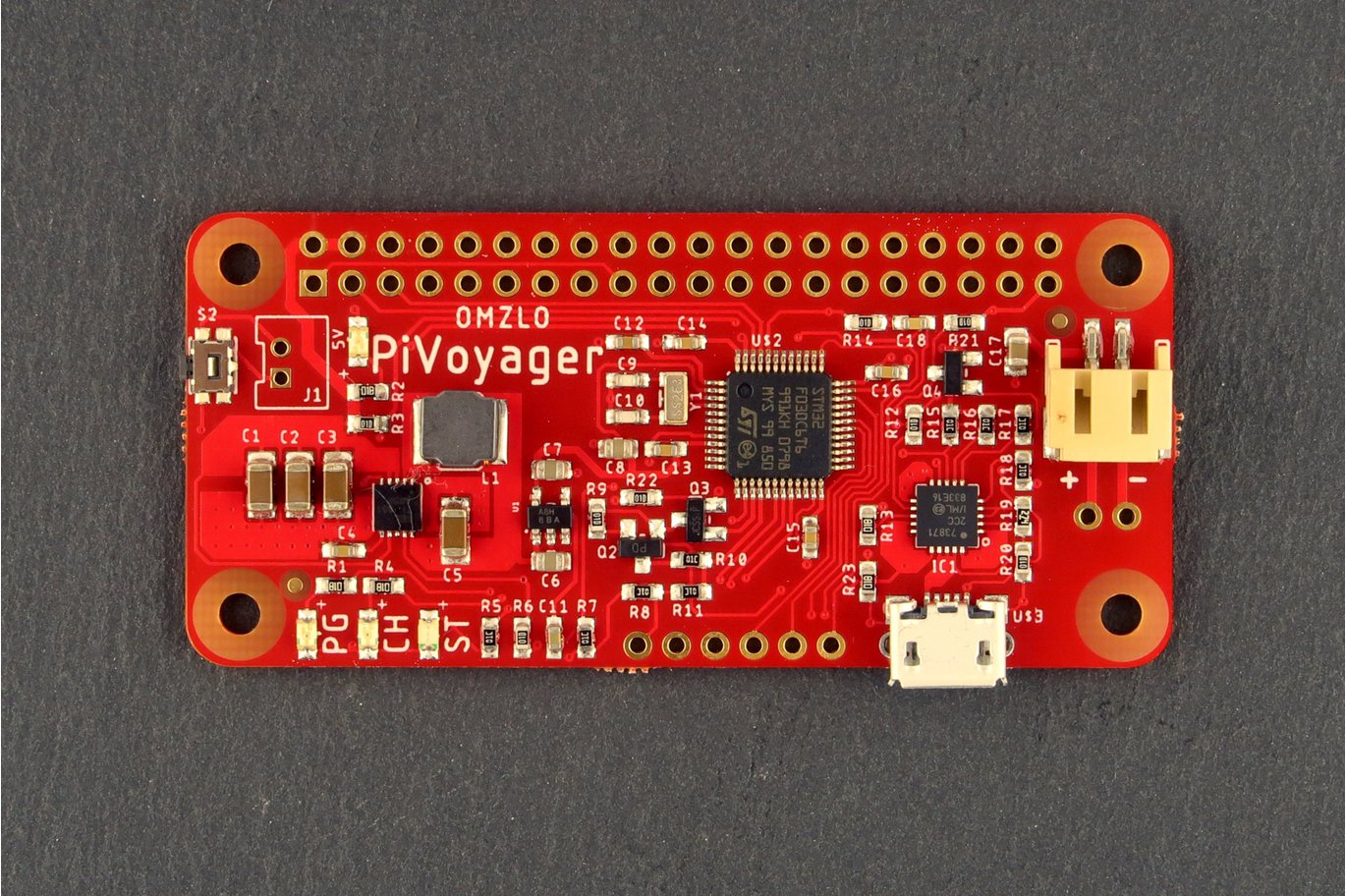
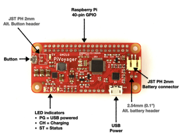
PiVoyager Layout
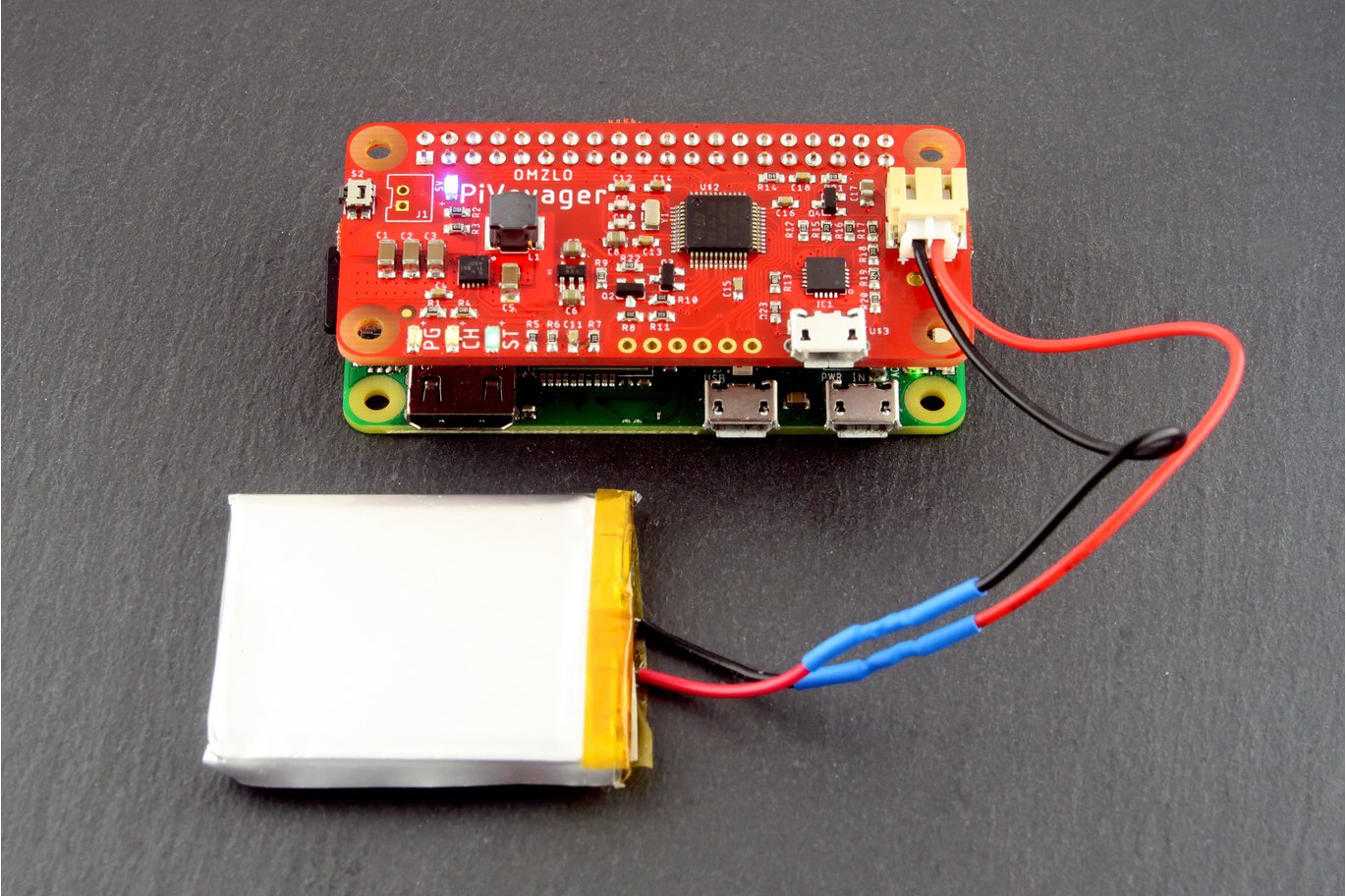
The PiVoyager is specially designed to work with standard LiPo or Li-Ion batteries as an uninterruptible power supply for the Raspberry Pi. It can power the Pi and at the same time charge a Li-Ion/LiPo battery. When the Hat is plugged to the USB power course, it powers and charges the Pi. It supports a default charge current of 1000mA and it is targeted at batteries with a nominal voltage of 3.7V and a charging voltage of 4.2V.
The PiVoyager will not only help to power your Pi but will also supply the right amount of power to it. It can automatically provide a maximum current of 2.1A at 5V to your Raspberry Pi even after the USB is removed without having to switch off the Pi. However, the PiVoyager doesn’t have an in-built battery protection circuitry, so, you have to be careful because things could go wrong if you mistakenly misconnect the terminals of your battery to the HaT.
The Pivoyager is available at Tindle for purchase for $34.66 (with VAT) and $27.95 (without VAT and shipping).
The PiVoyager is open-source and its schematics and firmware can be found on GitHub.
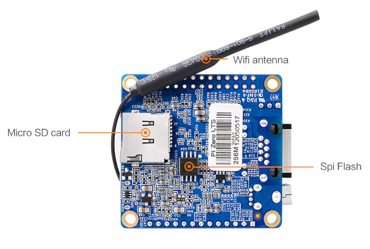
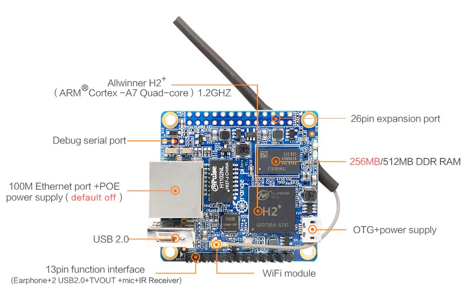
Orange Pi has launched their new Pi Zero LTS development board equipped with an Allwinner H2+ SoC. The Orange Pi Zero LTS, it is an update to Orange Pi Zero Allwinner H2+ board, and has the same specifications, but with changes to the hardware that Shenzhen Xunlong Software claims lower power consumption and reduced heat. Zero LTS features the same SoC and hardware as the Orange Pi Zero. The Orange Pi Zero’s less energy and less heat production features are good marketing strategies, especially for those who do not own the original Zero or have knowledge of it.
The SBC enables Armbian’s Debian and Ubuntu images and is most suitable for headless applications that require network connectivity via Ethernet and/or WiFi such as smart speakers. On the hardware features, the Orange Pi Zero LTS is based on an Allwinner H2+ SoC with quad-core Cortex-A7 processor with 256Mb or 512Mb of DDR3–1866 SDRAM, SPI Flash, and Mali-400MP2 GPU. It includes a micro SD card slot, 10/100 Ethernet port with PoE (default off), Allwinner XR819 module with 802.11b/g/n Wi-Fi with u.FL antenna connector and external antenna, USB 2.0 port, and micro USB port. For expansion features, there is an unpopulated 26-pin GPIO header compatible with the Raspberry Pi and a 13-pin header with headphone, two USB 2.0, microphone and IR receiver. There is no video output, except for the TV out on the header for composite video.
The SPI flash can be used to store U-boot, so network boot is possible without the need for a microSD card. Available also are a three-pin header for console/debugging applications, a pair of LEDs, and power supplied via micro USB port or PoE. As for software, Orange Pi offers Debian, Ubuntu, Raspbian, Android4.2/7.0, and OpenWRT images, although they are under the Orange Pi Zero category on the company’s download page, but if you want to avoid the stress of searching for images, go for one of the Linux images on Armbian website instead.
It worthy to note that at this point Orange Pi does not provide any official explanation on exactly how they improved the power consumption and heat reduction of the Pi Zero, it is most likely they lowered the SoCs voltage, which would also reduce its performance.
Specifications for the Orange Pi Zero LTS includes :
Connectivity – 10/100M Ethernet, 802.11 b/g/n WiFi via Allwinner XR819 module with u.FL antenna connector and external antenna, USB – 1x USB 2.0 host port, 1x micro USB OTG port, Expansion headers, Unpopulated 26-pin GPIO header mostly compatible with Raspberry Pi (1) header, 13-pin header with headphone, 2x USB 2.0, TV-out, microphone and IR receiver signals
Debugging – 3-pin header for serial console
Misc – 2x LEDs
Power Supply – 5V via micro USB port or optional PoE
Dimensions – 48 x 46 mm
Weight – 26 grams
You can buy the Orange Pi Zero LTS on AliExpress for the same price as the original model, which goes for $8.49 for the 256MB RAM version, and $10.49 for the 512MB model, excluding shipping costs.
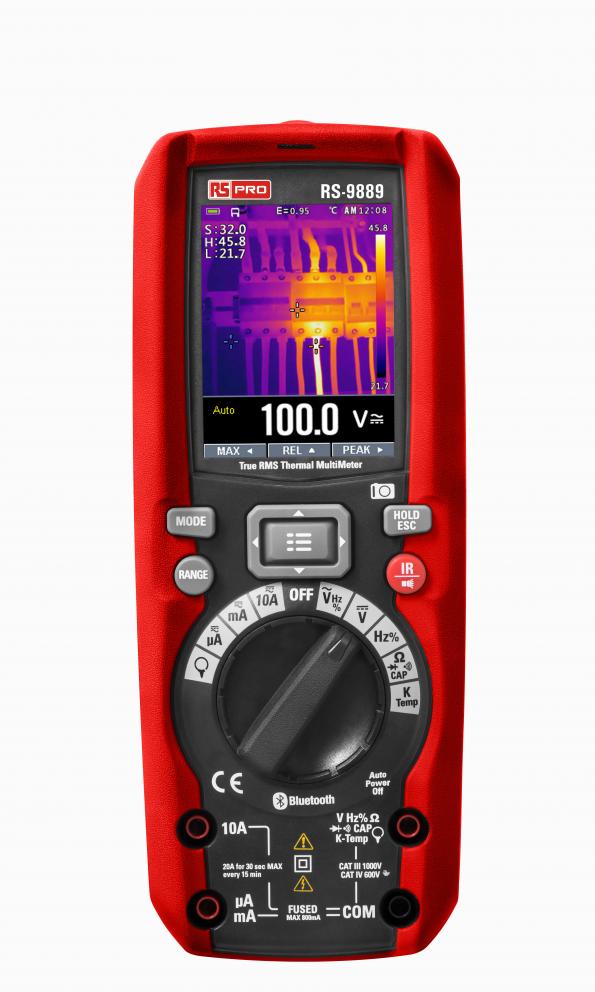
RS has launched the first digital multimeter (DMM) in the company’s RS PRO product range to integrate a built-in thermal imager. by Ally Winning@ www.eenewsembedded.com
The RS-9889 thermal imaging multimeter allows the identification of thermal overload issues in electrical equipment without the need for any physical contact. It is a handheld device designed to be cost-effective, while still being durable and reliable. The RS-9889 measures 80 x 58 x 195mm and weighs 540g.
The thermal imager of the RS-9889 offers maximum, minimum and centre crosshair targeting. A BLE connection allows the sharing of thermal images through the Thermview+ app. The imager has a 2.8-inch colour TFT LCD screen with an infrared resolution of 80 x 80 pixels, a 21° x 21° field of view, thermal sensitivity (NETD or noise equivalent temperature difference) to less than 0.1°C/100mK, a fast 50 Hz thermal image frame rate, an object temperature range from 20° to 260°C, a spectral range of 8–14 μm, and accuracy to within ±2°C, or ±2% of the reading.
Isolated high power Mosfet DC solid state relay shield allows you to control high current DC load in switching or PWM control mode. The project can be used in wide verity of applications like DC-DC Converters, inverters, DC motor control, solenoid, LED Dimmer, battery chargers and it can control inductive and resistive loads. On board high current fast recovery diode across the load provided for back EMF protection. The board can control load up to 25A with input supply up to 48V DC. High voltage DC input supply up to 90V is possible by altering DC bus capacitor voltage. Input PWM frequency up to 100 KHz duty cycle 0-100%. Mosfet power driver is isolated from Gate driver input. Gate driver circuitry requires 15V DC. Load supply 15V to 48V DC. Jumper J1 helps to use common supply for Arduino and gate driver. Screw terminal CN3 helps to connect load supply and load. Anode of gate driver connected to D3-PWM pin of Arduino to feed PWM signal or ON/OFF. P1 Potentiometer connected to Analog pin A0 of Arduino to adjust the PWM. Higher current Mosfets can be used to get more output current. Gate input requires TTL level signal.
Feature
Gate Driver Supply 15V
Load Supply 15V-48V
Load Current 25Amps
PWM Control: Arduino D3-PWM Pin
Potentiometer: Arduino Analog Pin A0
Jumper J1 : Close If common supply Arduino + Gate Driver
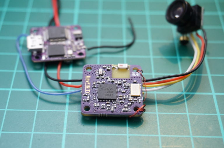
This is a tiny open source video transmitter with integrated graphic OSD from Simon Schulz @ fishpepper.de
Some time ago I got annoyed by the available OSD solutions and I started to look for alternatives. Nowadays small micro controllers are fast enough and include fancy features like DMA so that the OSD generation can be handled in software. I selected a STM32F3 due to the availability in small packages and the necessary features I needed and got working. In May 2017 I posted a first preview of my tinyOSD development on my blog. That time it was running on a tiny PCB and was meant to be inserted between your camera and video transmitter. I got up to a point where I had integrated full communication into a modified betaflight firmware and could do all kinds of fancy animations:
tinyOSD & tinyFINITY – a tiny opensource video tx with full graphic OSD – [Link]
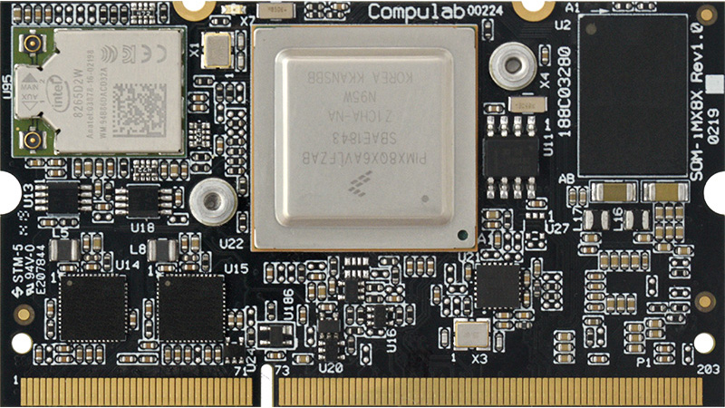
CompuLab introduces CL-SOM-iMX8X – a miniature System-on-Module built around the NXP i.MX8X System-on-Chip family.
High performance, powerful graphics and extensive connectivity make CL-SOM-iMX8X an excellent solution for a very wide range of applications such as industrial HMI, building control, image processing systems, IoT gateways, medical devices and metering systems.
CL-SOM-iMX8X has been designed to bring out the full I/O capabilities of the highly versatile i.MX8X SoC. Peripheral interfaces include PCI Express, dual Gigabit Ethernet, USB ports, 4 UARTs, 3 CAN-FD ports and 96 GPIOs. Display connectivity is supported with two independent LVDS / MIPI-DSI interfaces. In addition, CL-SOM-iMX8X extends the i.MX8X I/O even further with on-board 802.11ac WiFi, Bluetooth 4.2 and 3 additional USB ports.
CL-SOM-iMX8X is offered with full industrial temperature range of -40C to 85C.
Software Support
CL-SOM-iMX8X is provided with a full BSP and ready-to-run images for the Linux operating system. The CL-SOM-iMX8X BSP includes Linux kernel 4.14, Yocto Project SDK and U-Boot boot-loader.
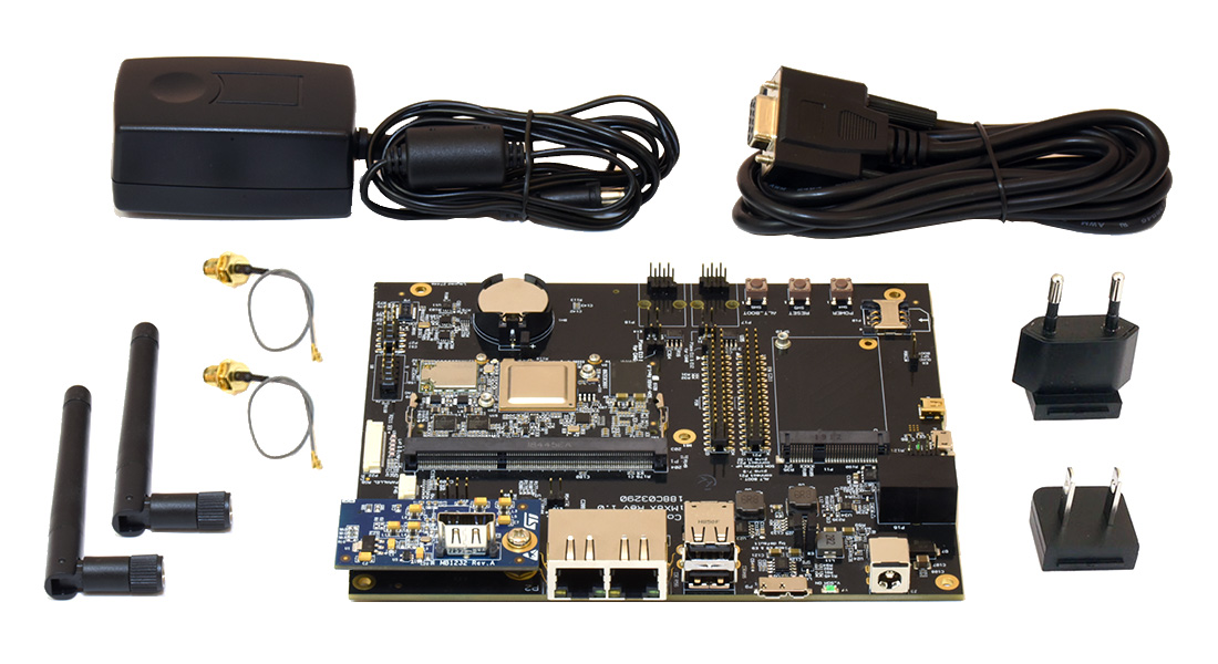
Evaluation and Design Support
To facilitate streamlined and rapid product development, CL-SOM-iMX8X is supported with the SB-iMX8X carrier-board and EVAL-iMX8X evaluation kit.
SB-iMX8X carrier-board has been designed for CL-SOM-iMX8X evaluation and application development. SB-iMX8X schematics, bill of materials and layout are available to be used as a reference design for a wide range of industrial use cases.
The EVAL-iMX8X eval-kit offered at $395, includes CL-SOM-iMX8X and SB-iMX8X hardware set, an optional LCD panel, PSU, cables and a technical support contract.
Feature Highlights
Up to 4GB LPDDR4 and 64GB eMMC
2x MIPI-DSI / LVDS, up-to 1080p60
2x GbE, WiFi 802.11ac, BT 4.2
mini-PCIe, 3x USB2.0, 2x CAN, RS485
Price and Availability
CL-SOM-iMX8X is available now through CompuLab’s worldwide distribution channels and through direct sales (www.compulab.com).
CL-SOM-iMX8X is offered at a variety of configurations starting from $73 for volume orders.
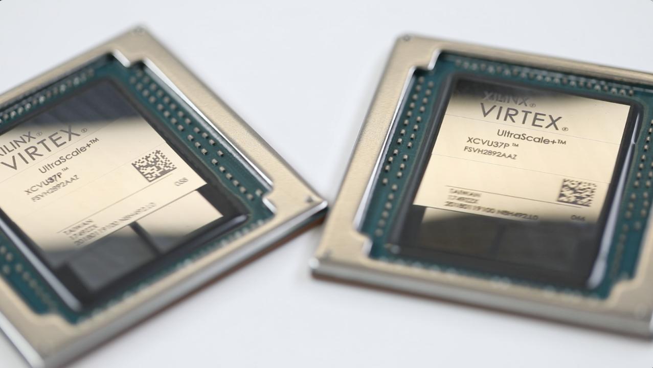
Xilinx has expanded its 16nm Virtex UltraScale+ family to include what it claims to be the world’s largest FPGA, the Virtex UltraScale+ VU19P. By Julien Happich @ www.eenewseurope.com
With 35 billion transistors, the VU19P provides the highest logic density and I/O count on a single device ever built, enabling emulation and prototyping of tomorrow’s most advanced ASIC and SoC technologies, as well as test, measurement, compute, networking, aerospace and defense-related applications.
Featuring 9 million system logic cells, up to 1.5 terabits per-second of DDR4 memory bandwidth and up to 4.5 terabits per-second of transceiver bandwidth and over 2,000 user I/Os, the new FPGA enables the prototyping and emulation of today’s most complex SoCs as well as the development of emerging, complex algorithms such as those used for artificial intelligence, machine learning, video processing and sensor fusion. The VU19P is 1.6X larger than its predecessor and what was previously the industry’s largest FPGA — the 20 nm Virtex UltraScale 440 FPGA.
“The VU19P enables developers to accelerate hardware validation and begin software integration before their ASIC or SoC is available,” said Sumit Shah, senior director, product line marketing and management, Xilinx. “This is our third generation of world-record FPGAs. First was the Virtex-7 2000T, followed by the Virtex UltraScale VU440, and now the Virtex UltraScale+ VU19P. But this is more than silicon technology; we’re providing robust and proven tool flows and IP to support it.”
The VU19P is supported by an extensive set of debug, visibility tools, and IP, providing customers with a comprehensive development platform to quickly design and validate next-generation applications and technologies. Hardware and software co-validation allows for developers to bring up software and implement custom features before physical parts are available. Moreover, the design flow can be co-optimized by using the Xilinx Vivado® Design Suite, which reduces cost and tape-out risk, and improves efficiency and time-to-market. The VU19P will be generally available in the fall of 2020.
Interested in controlling an object or device without physically touching it? So am I! For today’s tutorial, we will look how to build a DIY based Gesture Controlled Robotic Arm using the Microchip MGC3130 based, Seeed 3D gesture and position tracking shield for Raspberry Pi.
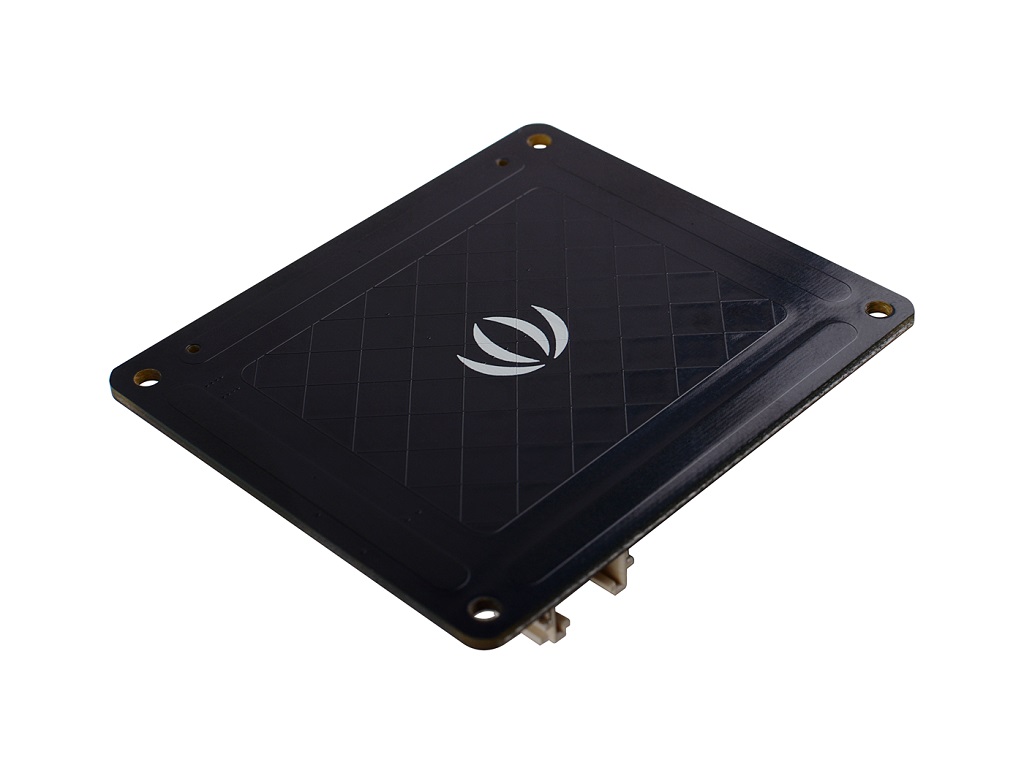
3D Gesture Tracking Shield
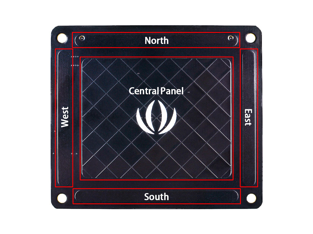
3D tracking has been one of the easiest ways of implementing Natural User Interfaces into devices as it allows users to interact with physical objects without touching them. This is exactly the capability that the Seeed 3D Gesture shield brings to the raspberry pi. This shield is based on the Microchip MGC3130 chip, which enables the Raspberry Pi with 3D gesture recognition and motion tracking function. It can capture x y z position information, can also do proximity sensing and touch sensing, support tap, and double click. As shown in the figure below, the recognition area is divided into two parts: the strip area distributed around and a central panel.
The strip areas can sense the orientation change, including the North, South, West, and East. The central area can sense touch, tap, double click, and gestures in the air area above the shield.
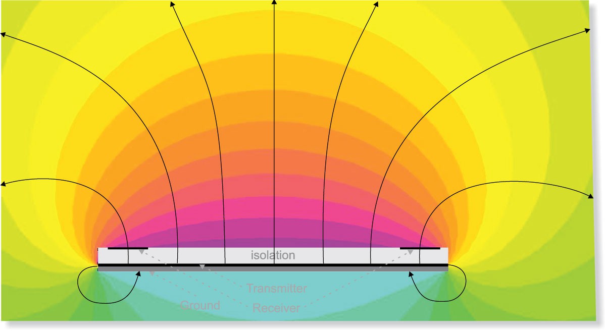
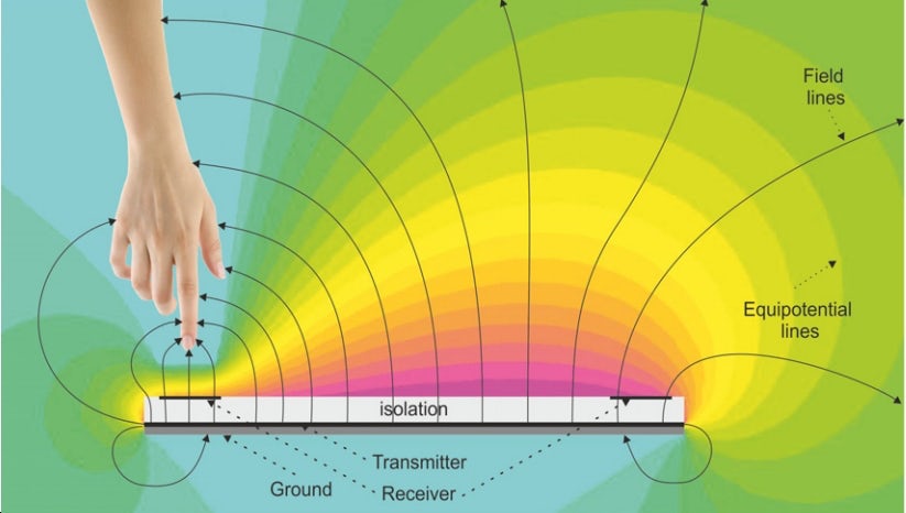
3D movements and gestures are detected by the shield using electrical near field sensing in line with Microchip’s patented GestIC® technology. The shield generates a magnetic field above the central panel and when the hand approaches, it will interfere with that magnetic field, and the magnetic field receiver below the shield will detect the change.
This hat communicates with Raspberry Pi via the I2C interface and also it has reserved a Grove I2C connector in case you need to work with other modules.
Some of the features of the shield include;
Recognition of 3D Hand Gestures and x, y, z Positional Data
Proximity and Touch Sensing
Built-in Colibri Gesture Suite (running on-chip)
Advanced 3D Signal Processing Unit
Detection Range: 0 to 10 cm
On-chip Auto Calibration
Compatible with various models of Raspberry Pi 2, 3, 4, and zero
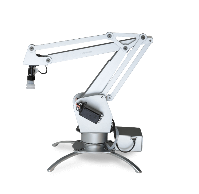
As mentioned in the introduction, for today’s tutorial, we will examine how a gestured controlled robotics arm can be built using this Gesture and Position shield, a Raspberry pi, and the uArm Metal Robotic Hand. The uArm Metal Robotic Arm is a DIY 4-axis parallel-mechanism, desktop robot arm, modeled after the ABB industrial PalletPack robot. It is made of metal but powered by small-sized more powerful servos, and can be controlled by an Arduino and other DIY boards.
uArm Metal Robot Arm
At the end of today’s tutorial, you will know how to build 3D gesture and position-controlled projects using the 3D gesture tracking shield, and also learn how to interface the uArm Robot Arm with a Raspberry pi.
Required Components
The components required to build this project include;
Raspberry Pi 3 (the Raspberry Pi 4, 2 or Zero will also work)
The components can be bought via the attached links. if you do not have access to the uArm Metal Robotic arm, you could also decide to 3d print your own robotic arm and couple them with off-the-shelf Servo motors, but please note this will not be compatible with the uArm library used under the code section.
Schematics
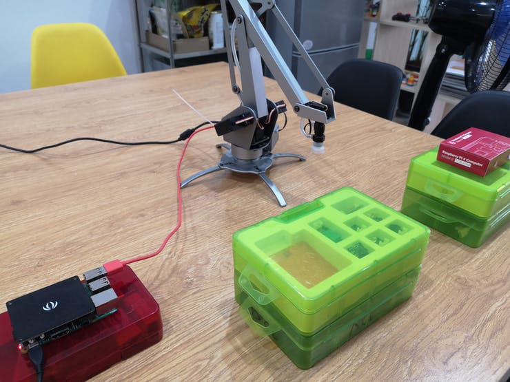
The Schematics for this project is quite simple due to the easy connection interface possessed by all the components. The 3D Gesture shield as the name implies comes as a shield, as such, it can be easily mounted on the raspberry pi as it is pin-compatible with the Raspberry Pi’s GPIO Layout. The uArm Robotic-arm also makes use of a USB interface through which it can be plugged directly into a USB port on the raspberry pi.
After connecting the components, your setup should look like the image below;
Setup
With this done you can now proceed to set up your raspberry pi and writing the python script for the project.
Preparing the Pi
Before we proceed to write the python script for the project, we need to set up the pi and install all the libraries that are necessary to get things going.
Today’s project as mentioned above is based on the Raspberry Pi 3 running the Raspbian stretch OS. While I believe it should work on the new operating system, I’d rather test before affirming. I will be assuming you understand the process of setting up Raspbian on the raspberry pi and connecting to it in headless mode via ssh or to a monitor via HDMI. If in doubt about any of these processes, you can check out several of our tutorials on setting up the Raspberry Pi.
Enable I2C
With the Pi up and running, the first thing we need to do is to enable I2C based Communication since the shield communicates with the Pi via I2C. To do this, if working with a monitor, click on the raspberry pi icon on the desktop, then select Preferences, and check the “enable” box for I2C.
If running in headless mode via a terminal software like putty, run;
sudo raspi-config
When the config panel opens, use the arrow keys on your keyboard to navigate and select “interface options”, select I2C and click enable and click yes when asked to reboot.
Install Libraries and Dependencies
With I2C enabled, we now need to install python libraries for MGC313o and uArm Robotic Arm.
To start with the uArm Robotic Arm library, Clone the git file by running;
with that complete, Change directory to the folder you just downloaded;
cd pyuarm
then run the installation script using;
sudo python setup.py install
with this done, you should now have the python library for the uArm robotic hand installed.
With the uArm library up and running, the next task is to install “ncurses“. ncurses is a python library that provides API like interfaces that allows the programmer to write text-based user interfaces in a terminal-independent manner and it is one of the dependencies required by the Seeed MGC3130 library. No need to worry too much about this. Start ncurses install by changing into the home directory by running;
then run the following one after the other to configure, make and install the library.
./configure
make
sudo make install
With this done, you can test the installation by running;
ncurses6-config --version
This should give you some information on the version of ncurses installed, or throw an error if it’s not properly installed.
With all the dependencies installed, you can now proceed to download the MGC3130 python library by Linux-Downey. Do this by changing into the home directory and running;
cd ~
git clone https://github.com/linux-downey/seeed_mgc3x30_python.git
change into the library folder, and run the flickrdemo example to test the library installation.
cd seeed_mgc3x30_python
./flick-demo
You should see a result similar to the image below.
With this done, we are now ready to write the code for this project.
Code
Based on the dependencies we have installed you should be able to deduce that the code for this project will be written with python. The code for this project is a modification to the flickrdemo example that came with the MGC3130 library. We will basically add code to control the uArm, changing only three of the functions already written in the demo example.
Writing python code can be pretty difficult using the terminal, for this part, I will advise you to switch to the Pi’s Desktop. If running in the headless mode, you can simply set up VNC Viewer on your host machine and activate the VNC Server on the Pi. This will allow you to access the Pi’s desktop without using a monitor.
On the Pi’s desktop, click on the Raspberry Pi logo, -> select programming -> and double click on python 2.7. Feel free to also use python 3 if you have it installed.
With python now open we can begin writing the code for the project. I will do a brief run through the code highlighting the major changes to the flickrdemo example.
Like with all my projects, we start by importing all the dependencies required for the project. For this, the only addition made to the library example is the addition of the pyuarm library.
#!/usr/bin/env python

import signal
import flicklib
import time
import curses
from curses import wrapper
import pyuarmarm= pyuarm.UArm()
Next, we create functions that determine what happens when specific gestures are detected by the Gesture board. For this, we will be modifying only four of the functions from the library example.
The first function is move(). This function is supposed to return the coordinates of the direction in which a hand gesture is moving.
@flicklib.move()
def move(x, y, z):
    global xyztxt
    xyztxt = '{:5.3f} {:5.3f} {:5.3f}'.format(x,y,z)
Next, is the flick function. This function is used to move the tip of the robotic arm up or down for picking and placing.
Next, is the air wheel function. This function basically states what you happen when you move your arms in a wheel form in front of the Gesture tracker. It is used to rotate the position of the robotic arm.
@flicklib.airwheel()
def spinny(delta):
global some_value
global airwheeltxt
some_value += delta
if some_value < 0:
some_value = 0
if some_value > 10000:
some_value = 10000
airwheeltxt = str(some_value/100)
arm.set_servo_angle(0, some_value/100)
Next is the double-tap function. this function determines what happens when the gesture board is tapped twice. For this project, it is used to turn “off” the robotic arm.
@flicklib.double_tap()
def doubletap(position):
global doubletaptxt
doubletaptxt = position
arm.set_pump(False)
Next, is the tap function. It dictates what happens when the 3D gesture tracker board is tapped once and was used in this project to turn the Robotic arm “on”.
@flicklib.tap()
def tap(position):
global taptxt
taptxt = position
arm.set_pump(True)
Lastly the touch position function. This provides the coordinates of any point point on the gesture tracker that is touched.
@flicklib.touch()
def touch(position):
global touchtxt
touchtxt = position
The functions above were the only part of the example code that was modified, all that is left is the main function and it is the same as the example with all it does being the detection of gestures and translating it using parameters defined by the library. If the gestures match any of the conditions for the functions above, they are called and the code within the function is executed.
The main function starts by including all the global variables that will be used and initializing the variables to zero.
def main(stdscr):
global xyztxt
global flicktxt
global airwheeltxt
global touchtxt
global taptxt
global doubletaptxt
xyztxt = ''
flicktxt = ''
flickcount = 0
airwheeltxt = ''
airwheelcount = 0
touchtxt = ''
touchcount = 0
taptxt = ''
tapcount = 0
doubletaptxt = ''
doubletapcount = 0
Next, the console is cleared and cursor hidden as Ncurses goes to work to create a GUI on the terminal.
# Clear screen and hide cursor
stdscr.clear()
curses.curs_set(0)
Next, the GUI is created with the title and footer also added.
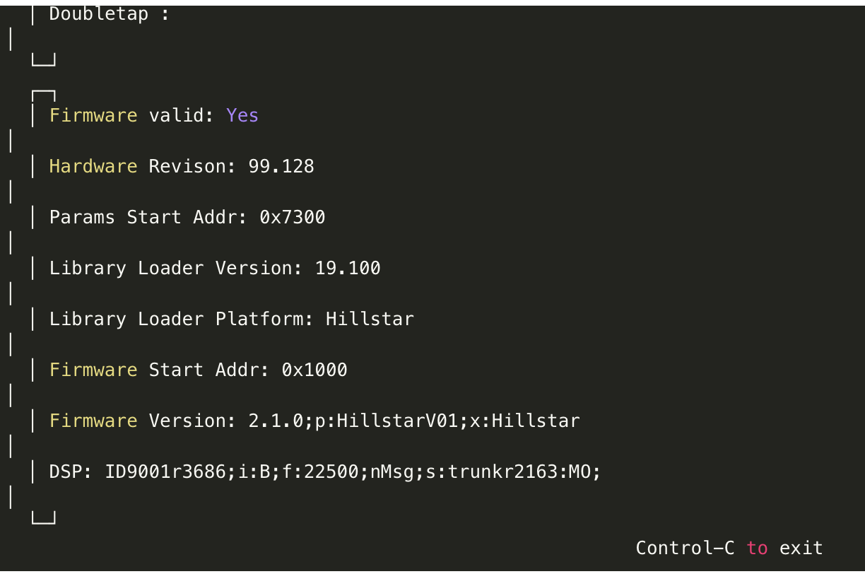
The firmware info part of the GUI Setup is filled. this just serves as a way of verifying that the PI is connected to the 3D gesture tracking sensor without issues.
With this done, the code then dives into a while loop which continuously polls the sensor to check for hand gestures and for every gesture that is recognized out of the 5 gestures we are looking for, it increments a variable matching that gesture by 1 which then triggers the function associated to it and the commands under the function are executed.
The Complete code for the project is available below and also attached along with the library under the download section of the tutorial.
#!/usr/bin/env python
import signal
import flicklib
import time
import curses
from curses import wrapper
import pyuarmarm= pyuarm.UArm()
some_value = 5000
@flicklib.move()
def move(x, y, z):
global xyztxt
xyztxt = '{:5.3f} {:5.3f} {:5.3f}'.format(x,y,z)
@flicklib.flick()
def flick(start,finish):
    global flicktxt
    flicktxt = start + ' - ' + finish
    if flicktxt == "east - west":
        arm.set_servo_angle(2, 30)
    elif flicktxt == "west - east":
        arm.set_servo_angle(2, 35)
@flicklib.airwheel()
def spinny(delta):
    global some_value
    global airwheeltxt
    some_value += delta
    if some_value < 0:
        some_value = 0
    if some_value > 10000:
        some_value = 10000
    airwheeltxt = str(some_value/100)
    arm.set_servo_angle(0, some_value/100)
@flicklib.double_tap()
def doubletap(position):
    global doubletaptxt
    doubletaptxt = position
    arm.set_pump(False)
@flicklib.tap()
def tap(position):
    global taptxt
    taptxt = position
    arm.set_pump(True)
@flicklib.touch()
def touch(position):
    global touchtxt
    touchtxt = position
#
# Main display using curses
#
def main(stdscr):
    global xyztxt
    global flicktxt
    global airwheeltxt
    global touchtxt
    global taptxt
    global doubletaptxt

    xyztxt = ''
    flicktxt = ''
    flickcount = 0
    airwheeltxt = ''
    airwheelcount = 0
    touchtxt = ''
    touchcount = 0
    taptxt = ''
    tapcount = 0
    doubletaptxt = ''
    doubletapcount = 0
# Clear screen and hide cursor
stdscr.clear()
curses.curs_set(0)
# Add title and footer
 exittxt = 'Control-C to exit'
 title = '**** Flick Demo ****'
 stdscr.addstr( 0, (curses.COLS - len(title)) / 2, title)
 stdscr.addstr(22, (curses.COLS - len(exittxt)) / 2, exittxt)
 stdscr.refresh()

 fw_info = flicklib.getfwinfo()

 datawin = curses.newwin( 8, curses.COLS - 6,  2, 3)
 fwwin   = curses.newwin(10, curses.COLS - 6, 11, 3)
# Fill firmware info window.
    fwwin.erase()
    fwwin.border()
    fwwin.addstr(1, 2, 'Firmware valid: ' + 'Yes' if fw_info['FwValid'] == 0xaa else 'No')
    fwwin.addstr(2, 2, 'Hardware Revison: ' + str(fw_info['HwRev'][0]) + '.' + str(fw_info['HwRev'][1]))
    fwwin.addstr(3, 2, 'Params Start Addr: ' + '0x{:04x}'.format(fw_info['ParamStartAddr']))
    fwwin.addstr(4, 2, 'Library Loader Version: ' + str(fw_info['LibLoaderVer'][0]) + '.' + str(fw_info['LibLoaderVer'][1]))
    fwwin.addstr(5, 2, 'Library Loader Platform: ' + 'Hillstar' if fw_info['LibLoaderPlatform'] == 21 else 'Woodstar')
    fwwin.addstr(6, 2, 'Firmware Start Addr: 0x' + '{:04x}'.format(fw_info['FwStartAddr']))
    fwver_part1, fwver_part2 = fw_info['FwVersion'].split(';DSP:')
    fwwin.addstr(7, 2, 'Firmware Version: ' + fwver_part1)
    fwwin.addstr(8, 2, 'DSP: ' + fwver_part2)
    fwwin.refresh()
 # Update data window continuously until Control-C
    while True:
        datawin.erase()
        datawin.border()
        datawin.addstr(1, 2, 'X Y Z     : ' + xyztxt)
        datawin.addstr(2, 2, 'Flick     : ' + flicktxt)
        datawin.addstr(3, 2, 'Airwheel  : ' + airwheeltxt)
        datawin.addstr(4, 2, 'Touch     : ' + touchtxt)
        datawin.addstr(5, 2, 'Tap       : ' + taptxt)
        datawin.addstr(6, 2, 'Doubletap : ' + doubletaptxt)
        datawin.refresh()

        xyztxt = ''

        if len(flicktxt) > 0 and flickcount < 5:
            flickcount += 1
        else:
            flicktxt = ''
            flickcount = 0

        if len(airwheeltxt) > 0 and airwheelcount < 5:
            airwheelcount += 1
        else:
            airwheeltxt = ''
            airwheelcount = 0

        if len(touchtxt) > 0 and touchcount < 5:
            touchcount += 1
        else:
            touchtxt = ''
            touchcount = 0

        if len(taptxt) > 0 and tapcount < 5:
            tapcount += 1
        else:
            taptxt = ''
            tapcount = 0

        if len(doubletaptxt) > 0 and doubletapcount < 5:
            doubletapcount += 1
        else:
            doubletaptxt = ''
            doubletapcount = 0

        time.sleep(0.1)

wrapper(main)
With the code complete, we can now proceed to try things out.
Demo
Save the code with whatever name you desire and run it. you should now be able to control the robotic hand by moving your hand in a different direction over the 3D Gesture tracker.
Demo
To better understand how the hand movements work, you can watch the video below to see the project in action.
Going Forward
While the application of the 3D gesture tracker in today’s project may not exactly fit your use case, it provides the basic building blocks for you to go on and build a powerful gesture tracking solution. From a gesture-controlled Robot to a gesture-controlled mouse for your computer, the possibilities are truly endless.
That’s it for this tutorial guys. Thanks for reading and following through. Feel free to reach out to me via the comment section with questions about any part of the project.
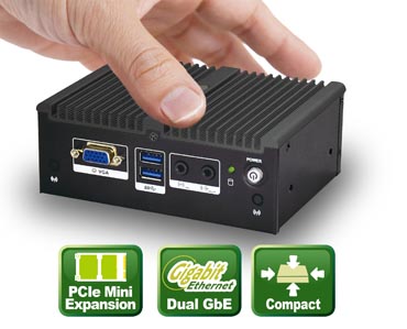
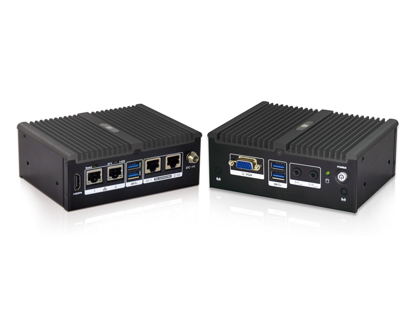
uIBX-250-BW is an ultra compact size industrial fanless embedded PC which supports Intel Celeron N3160 quad core processor. It supports maximum 8GB DDR3L SO-DIMM memory, HDMI and VGA dual display, two RS-232/422/485 ports, four USB3.0 ports, two Gigabit Ethernet LAN ports, one PCIe Mini slot. uIBX-250-BW is suitable for a wide range of industrial applications in the market, such as POS, Kiosk, ATM, Thin Servers, diskless workstations, building automation, project screens for department stores and supermarket, tour bus displays and much more.
Features
Intel® Celeron® N3160 Quad Core Processor up to 2.24GHz