Presenting the Common Emitter Amplifier
In the next three tutorials, including this one, we will present the three elementary topologies of bipolar transistors based amplifiers : the Common Emitter Amplifier, the Common Collector Amplifier and finally, the Common Base Amplifier.
We begin this series of tutorial by dealing with the most common type of amplifier found in an endless list of applications : the Common Emitter Amplifier that we will refer in the following as “CEA”.
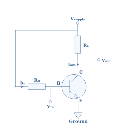
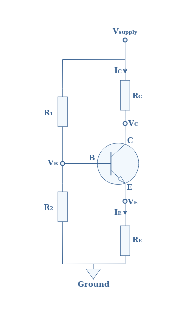
The first figure below presents the simplified electrical circuitry of a CEA configuration. The aim of Figure 1 is to purely show the general configuration of a CEA. However, some important elements of a real CEA architecture are missing and will be presented more in detail in the next section.

In this configuration, the input signal is delivered to the base branch, whereas the output is taken to the collector branch of the bipolar transistor. The name “Common Emitter” comes from the fact that the emitter branch is directly wired to the ground of the circuit.
Full CEA configuration
The simplified diagram given in Figure 1 does not include any biasing circuit, coupling and decoupling capacitors etc. A real circuit of a CEA configuration is given in Figure 2 :

First of all let’s deal with the added resistors:
- A resistance RL is in parallel with the resistance RC of the collector, it represents a load, that is to say the next stage of the circuit after the CEA : it can be an antenna, a speaker or simply another amplifier or stage of the electronic circuit.
- The resistance RS represents the internal resistance of the sine source.
- The resistor R1 and R2 are in parallel with the base branch of the bipolar transistor and form what is commonly known as a voltage network divider. This voltage divider as shown in the tutorial “Biasing a Bipolar Transistor in Common Emitter Configuration” is the most suitable biasing method since it improves the stability of the amplifier.
Moreover, three capacitosr have been added :
- The capacitor C1 and C3 are commonly known as “coupling capacitors”. The coupling capacitance C1 lets only the alternative current (AC) signal pass as an input of the CEA configuration while blocking the direct current (DC) to go from the supply to the source. The coupling capacitance C3 does the same by blocking any DC component coming from or going to the load RL. To summarize, C1 and C3 allow the AC signal to cross completely the CEA but blocks the DC signals to enter in the CEA.
- The emitter branch is wired to the ground through a “decoupling” or “derivation” capacitance C2. It is shown later in the tutorial the importance of this capacitance to amplify the voltage signal.
With this configuration, the DC is restricted to bias the CEA and it sinks to the ground while the AC can cross the CEA from the input to the output. Since this circuit works with DC and AC signals, both need to be taken into consideration when analyzing the CEA configuration as it is done in the next two sections.
Equivalent circuit in DC
In DC, the coupling and decoupling capacitor act as an open circuit. Considering this fact, the equivalent circuit in DC of Figure 2 is presented in Figure 3 below :
In this circuit, the base voltage VB is given by the network divider formula :
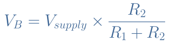
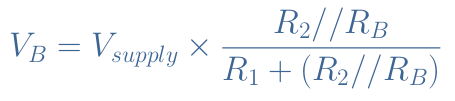
The base resistance RB is usually not considered in the calculation of VB since it is in a parallel configuration with the bias resistances and its value is most of the time at least superior of one order of magnitude than R2. However, for some configurations, this affirmation may not be valid or if one needs a high precision of the value of VB, the full formula should include the base resistance RB :
We can therefore express VE=VB-VBE where VBE=0.7 V is the threshold voltage of a silicon-based bipolar transistor.
Let’s suppose that the bipolar transistor current gain β is given by IC=β×IB with the collector current IC and base current IB, such as described in Figure 2. We have already mentioned just before that RB>>R2, moreover, since IE≅IC we can write from Figure 3 that RB×IB=RE×IC. When replacing IC by β×IB, the base current IB simplifies itself and we get the expression of the base resistance :

Equivalent circuit in AC
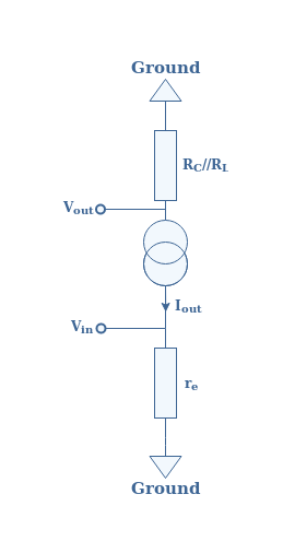
In AC, the coupling and decoupling capacitors are equivalent to a short circuit. Therefore, the emitter branch is shorted to the ground and the bias and collector are not included. Moreover, we introduce in the circuit a small diode emitter resistance re=25 mV/Iout that represents the dynamic resistance for small AC signals of the p/n junction of the bipolar transistor. When taking this into consideration, the equivalent circuit in AC of Figure 2 is given by Figure 4 below :
Input resistance
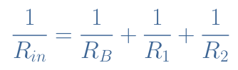
The total input resistance Rin of a CEA configuration is given by the parallel configuration of the bias and base resistances R1//R2//RB :
Output resistance
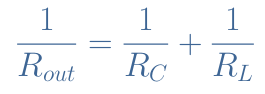
The total output resistance Rout of a CEA configuration is given by the parallel configuration of the collector and load resistances RC//RL :
Voltage gain
The voltage gain of a CEA configuration is simply defined by AV=Vout/Vin. When considering the circuit presented in Figure 4, we have Vout=Rout×Iout and Vin=re×Iout. The output current simplifies itself and the voltage gain is given by the ratio :
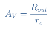
Equation 5 gives the expression of the voltage gain when the derivation capacitance behaves like a perfect short circuit, that is to say at high working frequencies.
Importance of the derivation capacitance
It is interesting to see the effect of the derivation capacitance C2 presented in Figure 2. Indeed, if this capacitance is not used, the emitter branch is not shorted to the ground in Figure 4 and the total resistance in this branch is RE+re instead of re. Therefore, the voltage gain becomes :
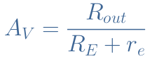
Usually the emitter resistance satisfies RE>>re so that we can approximate the voltage gain by AV=Rout/RE. Since the emitter resistance is much greater than the small diode resistance, the voltage gain is very much decreased.
As an example, typical values are : RC//RL=1 kΩ, RE=500 Ω and re=5 Ω.
- With no derivation capacitance, the voltage gain is AV=1000/505=1.98
- With a derivation capacitance, the voltage gain becomes AV=1000/5=200
The derivation capacitance in the emitter branch is therefore very important to amplify the voltage signal. Equation 6 gives the expression of the voltage gain when the derivation capacitance behaves as a perfect open circuit, that is to say at very low working frequencies or in DC mode.
Attenuation by the source
In Figure 4 we have not considered the source with its internal resistance RS presented in Figure 2. In reality, the voltage gain is affected by a factor VB/VS that represents the dimming produced by the small internal resistance of the source. The attenuated voltage gain is AV‘=AV×(VB/VS) and this factor is given by :
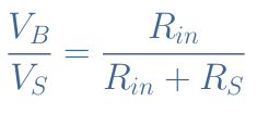
This factor is usually very close to 1 so often not considered to get an approximate value of the gain of a CEA configuration.
Current gain
The current gain is defined by AI=Iout/Iin where Iin=Vin/Rin and Iout=Vout/Rout. It comes then :
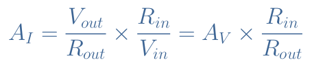
The voltage gain AV can be developed with the expression of Equation 5 which simplifies Rout and leaves :
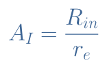
Since Rin>>re, the current gain of a CEA configuration is high.
Phase inversion
One very important characteristic of the CEA that we have yet not mentioned is that it inverts the phase of the output signals. Let’s consider for example a CEA with a voltage gain of 10 that has an input voltage of 2 V peak to peak and visualize both input and output voltages on the same figure :
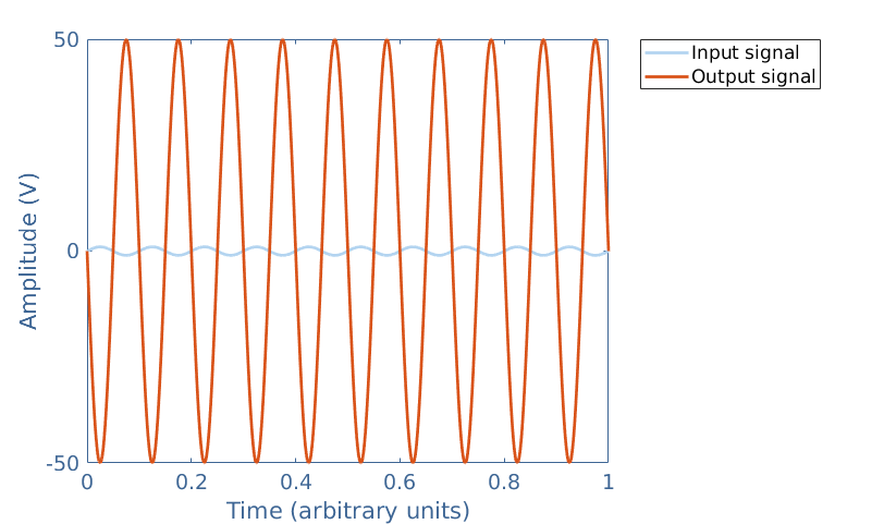
The phase inversion basically means that the maximum of the output voltage matches the minimum of the input voltage and the minimum of the output signal matches the maximum of the input signal.
Conclusion
In conclusion, we have seen how does a Common Emitter Amplifier (CEA) configuration behave. At first, a simplified circuit is presented to get introduced to the main aspects of this amplifier. We have seen afterwards the architecture of the full circuit of a CEA by understanding the role of bias and load resistor and coupling and decoupling capacitors. From analyzing the equivalent circuit in DC and AC modes, we have given the expressions of important parameters : the input and output impedance and the voltage and current gains. The CEA present high voltage and current gains that are enhanced by the presence of a derivation capacitance in the emitter branch, it also presents high input and output impedance, making it suitable as a universal amplifier for many applications. One other characteristic, specific only to CEAs is the phase inversion of 180 °=π rad between the input and output signals.
In the next tutorial we will analyze another type of amplifier that delivers the output from its emitter branch : the Common Collector Amplifier.