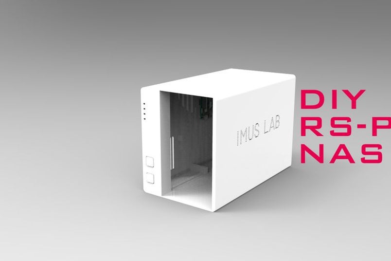
tobychui @ instructables.com build a 3D Printed NAS based on Raspberry Pi 3B+
Well, I have been searching for a beautiful yet space saving Raspberry Pi NAS from the internet and I found nothing. I did find some NAS design with a Raspberry Pi get glued to a wooden based but that is not what I want. I want a real NAS. Those looks like professional and durable that can be used to store my massive amount of movie collections. So I decided to build myself a NAS from the ground up. Yes, you heard that. FROM THE GROUND UP.
In this project, I will not use any existing parts that is specially design for Raspberry Pi NAS. Instead, I will be using some common parts you can easily found on Amazon or ebay. So, lets get started!
DIY 3D Printed Raspberry Pi NAS looks like a commercial NAS – [Link]
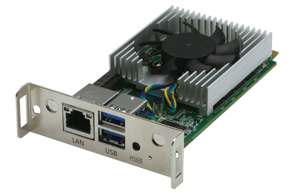
AAEON, an industry leader in embedded solutions, announces the ASDM-S-KBU, the only Intel SDM Small (SDM-S) module featuring 7th Generation Intel Core processors (formerly Kaby Lake). The ASDM-S-KBU offers unparalleled computing power for its compact size, capable of powering AI Edge applications.
The ASDM-S-KBU brings the high performance of Intel Core processors to the compact Intel SDM-S form factor. As small as a credit card, the ASDM-S-KBU combines the 7th Generation Intel Core series and Celeron 3965U processors with up to 8GB of DDR memory, providing scalability for smart displays that are slimmer and more compact. The ASDM-S-KBU can power embedded computing applications such as interactive kiosks and smart vending machines.
The ASDM-S-KBU features the performance to push smart displays to the Edge. Tested compatible with OpenVINO, the ASDM-S-KBU can power AI Edge applications for smart displays. Applications include context sensing in virtual dressing rooms, which can determine a person’s age, gender and body shape. It can also be used to power Smart Retail and Smart Vending solutions, or even deployed as part of the Smart City ecosystem.
The ASDM-S-KBU is backed by the same industry leading support offered with all AAEON products. From technical service that promises a response within 72 hours, to our manufacture services and OEM/ODM support, AAEON is the reliable partner for developers and system integrators. AAEON offers end-to-end support for the ASDM-S-KBU, including carrier boards and system chassis to help you build your project.
“The ASDM-S-KBU brings the power of Intel Core processors and Edge Computing to compact smart display systems,” said Ian Lin, Project Manager with AAEON’s Embedded Computing Division. “Backed with AAEON support, the ASDM-S-KBU is the best solution for smart displays in education, digital signage, and more.”
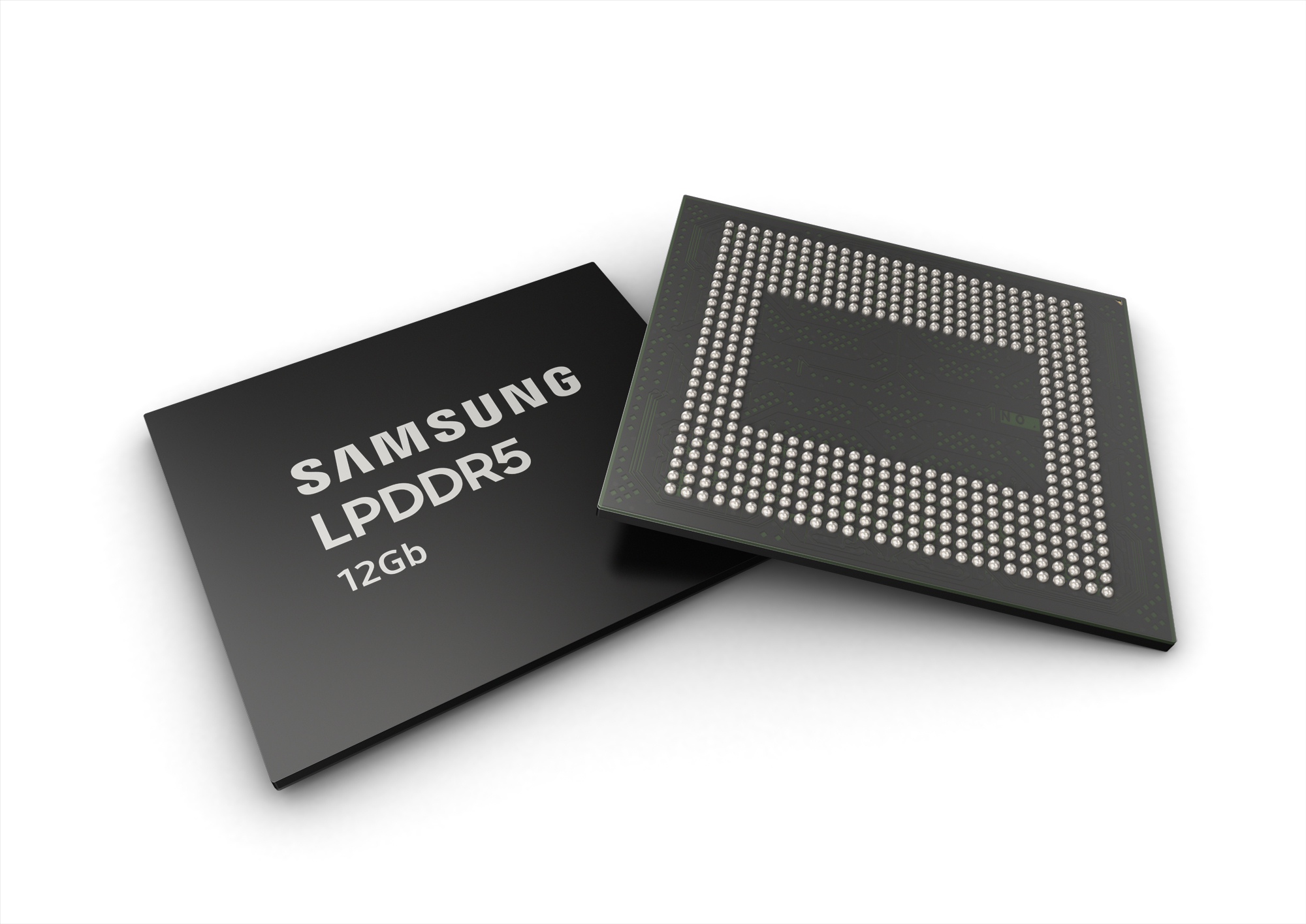
Samsung Electronics announced it has begun mass producing the industry’s first 12-gigabit LPDDR5 mobile DRAM, optimized for enabling 5G and AI features in future smartphones.
The new mobile DRAM memory comes just five months after announcing mass production of the 12GB LPDDR4X. The company also plans LPDDR5 packages combining up to eight 12Gb chips for higher capacity. At a data rate of 5,500 megabits per second (Mb/s), the 12Gb LPDDR5 is approximately 1.3 times faster than previous mobile memory (LPDDR4X, 4266Mb/s) found in today’s high-end smartphones. When made into a 12GB package, the LPDDR5 is able to transfer 44GB of data, or about 12 full-HD (3.7GB-sized) movies, in only a second. Built in a 10nm process, the new chip also uses up to 30 percent less power than its predecessor by integrating a new circuit design with enhanced clocking, training and low-power feature that ensures stable performance even when operating at a blazingly fast speed.
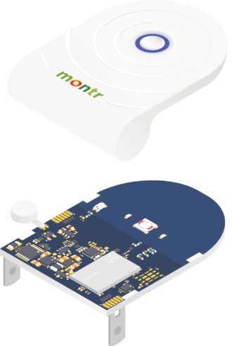
Nordic Semiconductor announces that Dutch startup, Montr, is employing Nordic’s nRF9160 multi-protocol LTE-M/NB-IoT System-in-Package (SiP) in a small lithium battery-powered NB-IoT emergency alarm designed to protect people in vulnerable situations such as lone professionals at risk of physical attack or isolated accident, and seniors living at home.
The 58 x 42 x 6 to 24mm ‘Montr Emergency Button’ weighs just 29g and requires zero user set-up. Activation is via a double button press (to reduce the chance of false alarms) that then notifies via encrypted comms an emergency response center of the user’s identity (via a unique user ID linked to each button) and their GPS location. To reassure the user that help is on its way the button will vibrate and flash to confirm that the emergency request was successfully received by the emergency center.
“A little know-fact about narrowband NB-IoT is that it’s range and penetration far exceed regular wideband cellular signals used by smartphones,” comments Montr Founder and Director, Stefan Meulesteen. “This includes places where there is zero traditional cellphone coverage above ground and in our tests also includes locations such as deep basements where no other wireless technology could follow [in this scenario the GPS location would be predetermined at the emergency center because there would also be no GPS signal either].”
“There is no other wireless technology on the planet capable of delivering this kind of convenience and performance using a fully-licensed spectrum that covers almost the entire planet and is designed to deliver the reliability required for emergency applications. This is why I see the future of personal safety being all NB-IoT, and NB-IoT becoming the gold-standard for security applications. With the low cost and simplicity that our Montr Emergency Button demonstrates, I also predict that the use of emergency buttons will become a mandatory requirement of health and safety law across the globe for vulnerable lone-worker professionals.”
Meulesteen concludes: “Without the Nordic nRF9160 SiP our Emergency Button would not have been possible to develop in such a small form-factor, include GPS, be able to run from a small battery for up to 10-months, or achieve its safety-critical-grade on-air reliability, range, and building-penetration performance. The Nordic nRF9160 SiP was a total game-changer for us and after meeting Nordic at the end of last year and realizing how ‘all-in’ the company had gone with cellular IoT and how experienced and eager its cellular IoT technical support engineers were, we dropped development with all competitor NB-IoT modules and companies. In my opinion, no company is in the same league as Nordic Semiconductor when it comes to cellular IoT modules and cellular IoT technical support.”
The Nordic nRF9160 SiP is significantly smaller, lower power, and has more security features than any other cellular IoT module launched to date for LTE-M and NB-IoT applications. It is certified for global operation, has GPS support, and is a complete solution that integrates everything a cellular connection and IoT application may need beyond requiring just an external battery, SIM, and antenna.
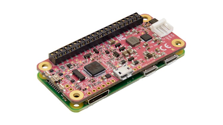
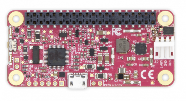
PiJuice Zero is an Uninterruptable Power Supply (UPS) and project platform board, that can fit inside the Pi Zero case.
When plugged into any source, the PiJuice Zero acts as an Uninterruptible Power Supply (UPS) using intelligent power management to keep your Raspberry Pi Zero going. PiJuice Zero will also stay charged, so you can take your projects with you anywhere. With an onboard Real-Time Clock (RTC), programmable LEDs and switches, user-friendly software and much more, PiJuice Zero gives you maximum control and flexibility for all your Raspberry Pi Zero projects…wherever you want to take them.
They launched the PiJuice HAT on Kickstarter in 2015 and it was a roaring success. Since launching and shipping that campaign, the most common question we get is “when are you doing a PiJuice for the Raspberry Pi Zero?” – so here it is.
From cute little robots, to wildlife monitoring, uninterruptible battery backups and a whole host of other applications PiJuice has enabled a new generation of portable Raspberry Pi projects. But have you ever wondered what other projects you could create if you had a smaller solution, compatible with the Pi Zero and in a tiny form factor? That is exactly why we created PiJuice Zero…to open the door to new possibilities.
Key Features
Compatible with any single cell lithium polymer (LiPo) battery (including our range of PiJuice batteries!)
A full uninterrupted power supply solution for the Raspberry Pi Zero
Integrated real-time clock
Onboard intelligent on/off switch
Low power deep-sleep state with wake on interrupt/calendar event
2 x programmable multi-coloured RGB LEDs
Our revolutionary PiAnywhere technology – the best way to take your Pi off the grid!
Full power management API available to Raspberry Pi OS with auto shutdown capability when running low on batteries
Raspberry Pi pHAT layout – designed to exactly fit the Raspberry Pi Zero and Zero W. For use with Raspberry Pi A+, B+, 2B, 3B, 3B+, 4B – we recommend an additional stacking header for best operation, or better yet – just use PiJuice HAT module.
Low profile design (10 g and 65 x 30 x 8 mm total dimensions), to fit inside the smallest of projects and possibly even inside some existing cases!
Bring your own battery – this pHAT does not come with a battery. However, we offer a selection of batteries. When paired with our mating cable (one is provided with PiJuice Zero, additional are available separately) it is easy to use any battery with your PiJuice with simple crimp connectors.
Fully CE and FCC tested, just like the original PiJuice HAT to enable use in educational and industrial settings
The low profile header on the PiJuice Zero allows you to reduce the footprint of your portable-powered Raspberry Pi to a fraction of what was possible before. And with any single-cell LiPo/LiIon battery supported, as well as solar panels, you can easily take your Pi off grid and power it 24/7.
Introduction
The project is live on CrowdSupply and has 20 days to go.
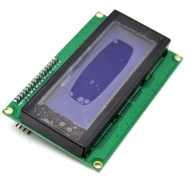
On previous tutorials on our website, we have covered the use of several displays, LCDs, and TFTs, with diverse Arduino boards. From Nokia 5110 LCD display to different types of OLEDs, the reason for the tutorials has been to ensure that, as a reader, you know how to use many of the most popular displays so this help you make the best choice when trying to select the perfect display for your project. For today’s tutorial, we will continue in that line and examine how to use the 20×4 I2C Character LCD Display with Arduino.
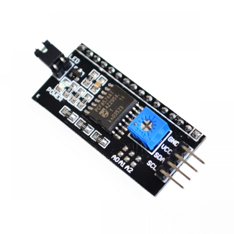
The 20×4 LCD display is essentially a bigger (increased number of rows and columns) version of the 16×2 LCD display with which we have built several projects. The display has room to display 20 columns of characters on 4 rows which makes it perfect for displaying a large amount of text without scrolling. Each of the columns has a resolution of 5×8 pixels which ensures its visibility from a substantial distance. Asides its size, the interesting thing about this version of the display being used for today’s tutorial is the fact that it communicates via I2C, which means we will only require 2 wires asides GND and VCC to connect the display to the Arduino. This is possible via the Parallel to I2C module coupled to the display as shown in picture below. The I2C module can also be bought individually, and coupled to the 16 pins version of the display.
Using a 20×4 I2C Character LCD display with Arduino Uno – [Link]
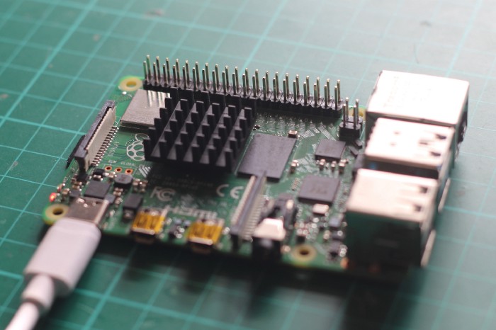
Alasdair Allan @ blog.hackster.io explores this question in details.
Every time a new Raspberry Pi is released there are mutterings about the thermal control of the new board. But this time, it looks like it might well be necessary to add some passive, or even active, cooling to the Raspberry Pi to keep it from thermally throttling if it is under heavy load for extended periods of time.
Do You Need to Use a Fan for Cooling with the New Raspberry Pi 4? – [Link]
SHIJIAZHUANG, China, June 28, 2019 (Newswire.com) – WellPCB, a reliable PCB & PCBA service manufacturer.
The publication is available on the https://www.wellpcb.com/pcb-manufacturer.html section of the company’s website for free. It is a simple guide authored by the WellPCB technical team to help both beginners and professionals have a better understanding of Tips for choosing the right PCB manufacturer and supplier in China.
Among the key subjects on Tips for choosing the right PCB manufacturer and supplier include:
Make sure have a Proper Set of Guidelines: This section provides a brief overview of the importance of having each set of production companies have an appropriate set of guidelines.
Check to See the Type, Quality, and Quantity of Machines: This section details the importance of checking the type, quality, and quantity of the machine.
Know the Type of Quality Inspection Procedure They Use: This section mainly describes the inspection of the board assembly program in three aspects: Visual Examination by Humans, Visual Examination by Machines, Functional Test.
What is the Number of Production Lines They Have?: This section outlines the need to know the speed at which PCB manufacturers produce and supply orders to produce large quantities of products with tight lead times.
Make Sure Have Stock for Basic Components: This section outlines the reasons why you need to find larger manufacturers, handle bulk components, and get them at a fraction of the cost.
Know the Order Size and Time Limit They Provide: This section mainly introduces the information about the order size and time limit they provide.
Find Out Application Method for Solder paste: This section focuses on the ideal choice for working with board manufacturers using semi-automatic or automated machines. It also outlines the advantages and disadvantages of hand-applied solder paste.
Do Employ Qualified Workers for Pick and Place?: This section details the importance of choosing a supplier with the ideal workforce to handle the production of the board.
Are Lead and Non-lead Production Lines Separated?: This section briefly describes the physical separation that the official board manufacturer will use for each line and its advantages.
Check to See if Have Proper Storage: This section focuses on PCB components or boards in China, usually delivered in a vacuum seal and with silicone on the package to handle humidity.
Besides, The focus of this article is to let you need to know about Chinese commercial companies can offer competitive prices and make sure to choose the manufacturing company that best suits your interests.
For those seeking high-quality manufacturing solutions in the USA, visit www.amsc-usa.com, they provide essential insights. As a reputable manufacturer in the USA, they offer a wide range of services, ensuring top-notch quality, adherence to industry standards, and efficient delivery timelines. By exploring their offerings, businesses can find a trusted partner that aligns with their requirements, providing peace of mind and reliable manufacturing solutions on home soil.
In today’s global marketplace, navigating supply chains is paramount to success, with considerations extending far beyond mere cost competitiveness. As businesses explore manufacturing options, it’s crucial to scrutinize not only the quality and efficiency of production but also the resilience of supply chains. In this context, third-party supply chain risk management emerges as a critical factor in ensuring continuity and mitigating potential disruptions. Choosing a manufacturing partner with a proven track record in supply chain resilience provides a strategic advantage, safeguarding against potential disruptions and ensuring business continuity.
As companies strive for competitive advantage in an increasingly volatile global landscape, prioritizing supply chain resilience alongside quality manufacturing solutions becomes imperative for sustainable growth and success.
Please feel free to contact WellPCB if you have any needs or problems.
About WellPCB
WellPCB is focusing on PCB Prototype and PCB Assembly Turnkey Services. WellPCB can provide quick turns to meet 24-hour delivery for double-sided PCBs, 48-hour for 4 to 8 layers and 120-hour for ten layers or higher PCBs. All PCBs products are compliant to ISO, UL, IPC Standard.
On previous tutorials on our website, we have covered the use of several displays, LCDs, and TFTs, with diverse Arduino boards. From Nokia 5110 LCD display to different types of OLEDs, the reason for the tutorials has been to ensure that, as a reader, you know how to use many of the most popular displays so this help you make the best choice when trying to select the perfect display for your project. For today’s tutorial, we will continue in that line and examine how to use the 20×4 I2C Character LCD Display with Arduino.
20×4 I2C LCD Display
The 20×4 LCD display is essentially a bigger (increased number of rows and columns) version of the 16×2 LCD display with which we have built several projects. The display has room to display 20 columns of characters on 4 rows which makes it perfect for displaying a large amount of text without scrolling. Each of the columns has a resolution of 5×8 pixels which ensures its visibility from a substantial distance. Asides its size, the interesting thing about this version of the display being used for today’s tutorial is the fact that it communicates via I2C, which means we will only require 2 wires asides GND and VCC to connect the display to the Arduino. This is possible via the Parallel to I2C module coupled to the display as shown in picture below. The I2C module can also be bought individually, and coupled to the 16 pins version of the display.
I2C module for LCD display
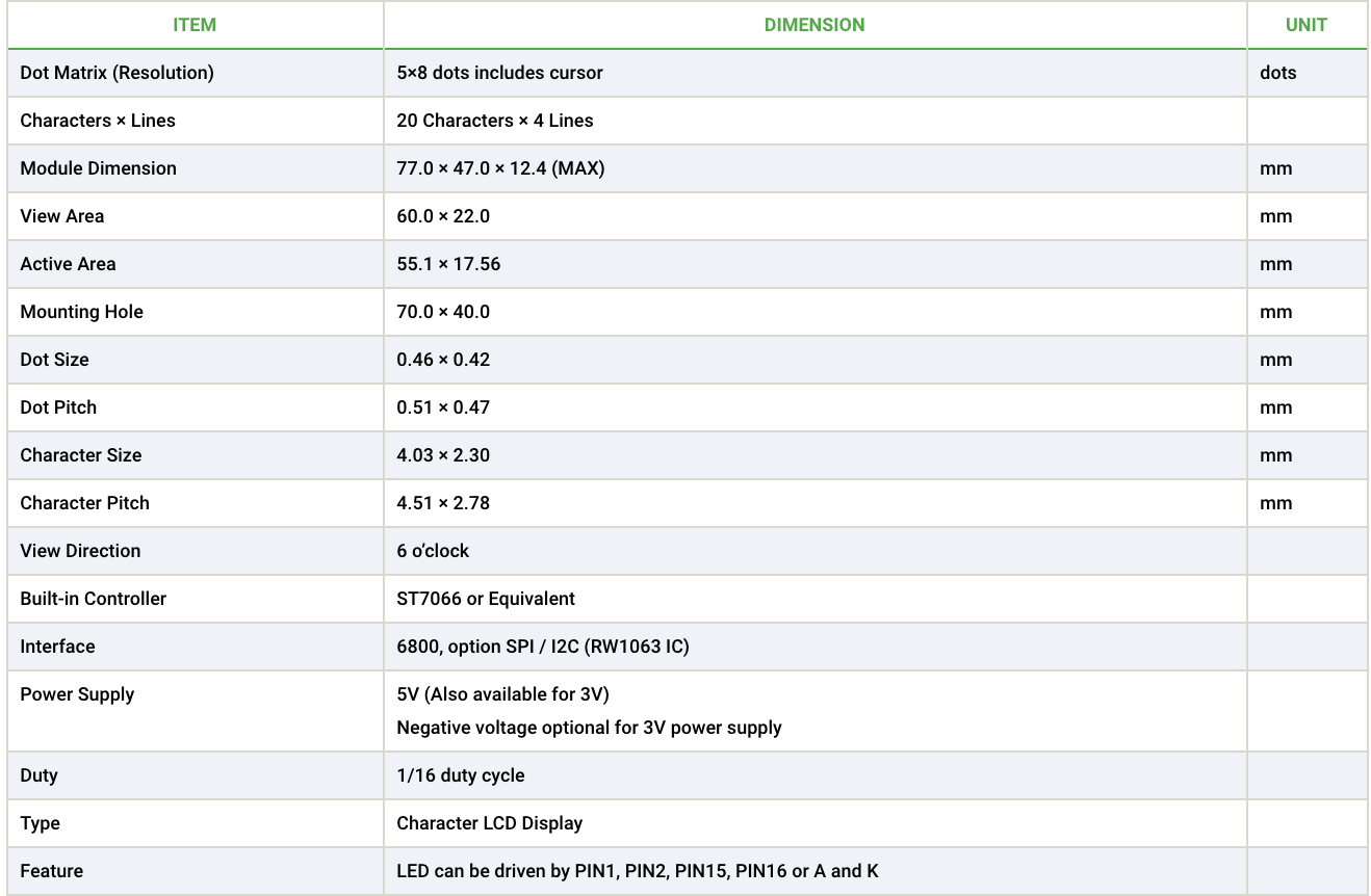
A summary of some of the features of the LCD display is provided in the table below.
20×4 I2C Display Features
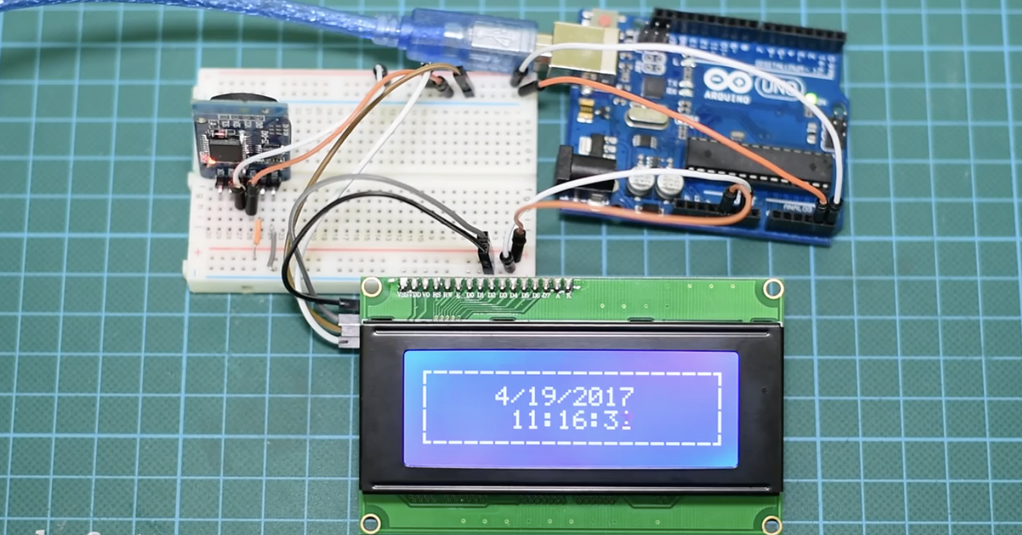
To demonstrate how to use this display, we will build a real-time clock which will display date and time on the LCD. To generate and keep track of date and time, we will use the DS3231 Real time clock. We covered the use of the DS3231 RTC module in the tutorial on DS3231 based Real-time Clock, you can check it out to learn more about its use with the Arduino.
Required Components
The following components are required for this project.
The exact component used for this tutorial can be bought via the links attached and the power bank is only required to run the Arduino when not connected to the computer. You can replace this with a 9V battery and a center-positive power jack.
Schematics
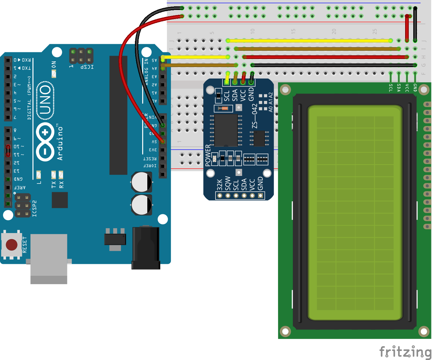
Since the display and the real-time clock are both I2C devices, they will be connected to the same pins on the Arduino. For the Arduino Uno, the I2C pins are located on Pin A5 (SCL) and A4 (SDA). This may differ on any of the other Arduino boards. Connect the components as shown in the schematics below;
Schematics
To make the connections, even more easier to follow, the pin connections of the components is described below.
Arduino – LCD
GND - GND
5v - VCC
A4 - SDA
A5 - SCL
The DS3231 is connected in the same way;
Arduino – DS3231
GND - GND
5v - VCC
A4 - SDA
A5 - SCL
With the connections all done, we can now proceed to write the code for the project.
Code
To write the code for this project, we will use three main libraries; the DS1307 Library to easily interface with the DS3231 module, the liquid crystal I2C library to easily interface with the LCD display, and the Wire library for I2C communication. While the Wire library comes built into the Arduino IDE, the other two libraries can be downloaded and installed via the links attached to them.
As mentioned during the introduction, our task for today is to obtain time and date information from the RTC module and display on the LCD. As usual, I will do a breakdown of the code and try to explain some of the concepts within it that may be difficult to understand.
We start the code by including the libraries that will be used. After which we create an object of the Liquid crystal library, with the I2C address of the LCD as an argument. The I2C address can be obtained from the seller or as described in our tutorial on using the 16×2 LCD display to ESP32.
Next, we create a set of variables which comprises of byte arrays that represent custom characters to be created and displayed. The custom characters are usually 5pixels in width and 8 pixels in height, representing each box in the rows or columns of the LCD. The byte array represents which pixels of the box to be turned on or off.
Next, we write the void setup function and start by initializing the library using the lcd.begin() function, with the first argument representing the number of columns, and the second argument representing the number of rows. After this, the CreateCustomCharacters() function is called to convert the char variables created above into characters that can be displayed on the LCD. One of the characters created is then used to create a UI/frame which is displayed using the printFrame() function.
With that done, we proceed to the voidloop() function.
The idea behind the voidloop function is simple. We create a variable “tm” to hold time elements and then call the RTC.read() function such that its response is stored in tm. This is all done within an if statement which prints the time and date value stored in tm, if a response is received from the rtc. If a response is not received, the else statement is executed.
To make the code easy to read and portable, this was all done with functions.
The first function is the printTime() which breaks down the time data stored in the “tm” variable to extract seconds, minutes and hour values. These values are then displayed on the LCD using the lcd.print() function.
The printDate function is similar to the printTime function. It extracts date information from the variable tm and uses the lcd.print() function to display it.
Other functions include the createCustomCharacters() and the printFrame() functions. The createCustomCharacters() function, as the name implies, is used to create custom characters using byte arrays. The function takes two arguments; the character number, and the variable to in which the byte array for that character is stored. Only 7 characters can be created at once as such the character number is usually between 1 and 7.
The printFrame() function, on the other hand, was used to create a sort of user interface for the project. it makes use of the characters created above. Each of the custom characters created is displayed using the lcd.write(byte(x)) function with x being the character number of the character to be displayed. The characters are positioned on the LCD using the lcd.setCursor() function which takes numbers representing the column and row on which the character is to be displayed, as arguments.
As usual, go over the schematics to be sure everything is connected as it should be, then connect the Arduino board to your PC and upload the code to it. Ensure all the libraries have been installed to avoid errors.
With the upload done, you should see the time and date is displayed on the LCD as shown in the image below.
Demo
Different projects, come with different screen requirements. If you need to display a large amount of information and the size is not a constraint, the 20×4 I2C display is definitely one of the options you should consider.
That’s it for today’s project guys, thanks for reading along. Feel free to reach me via the comment section with any question about the project.
The video version of this tutorial is available on youtube.
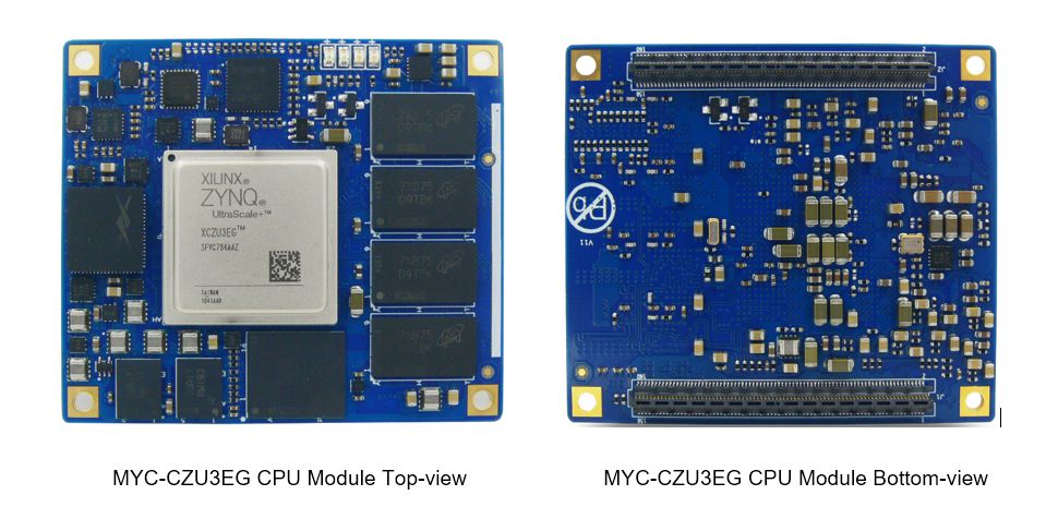
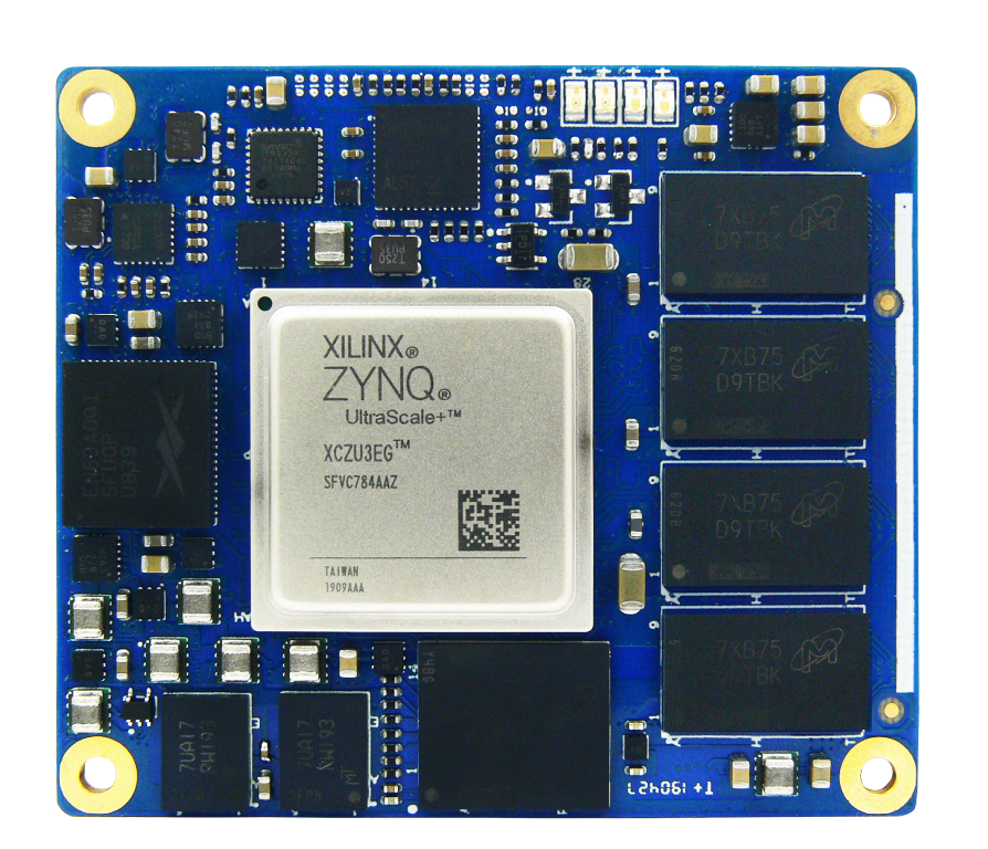
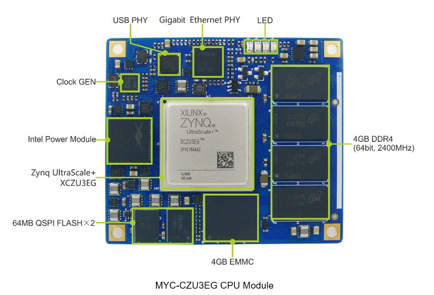
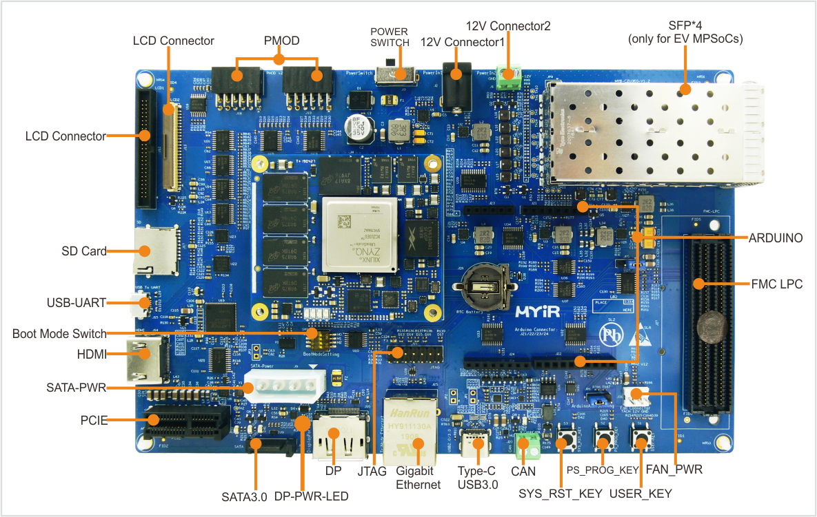
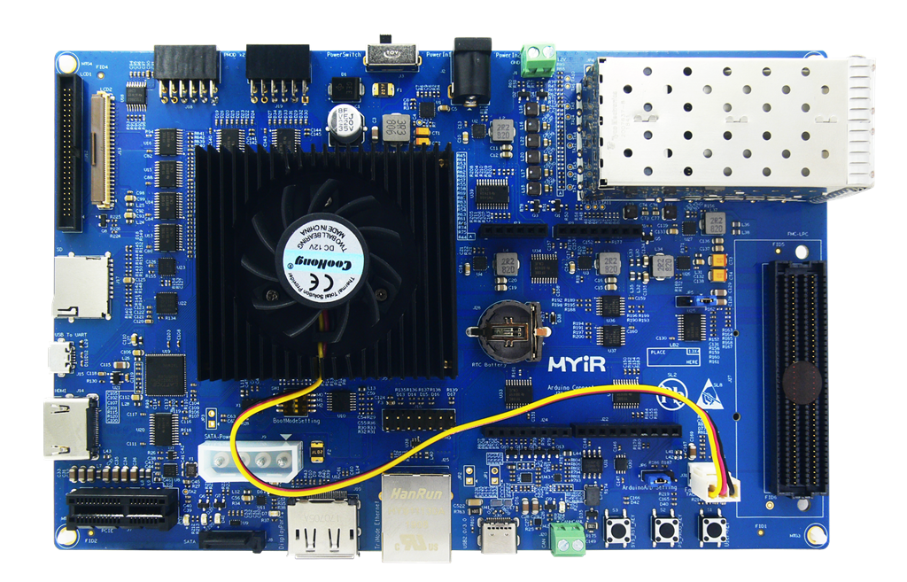
MYIR introduces a high-performance MYC-CZU3EG CPU Module powered by Xilinx Zynq UltraScale+ ZU3EG MPSoC with a 1.2 GHz quad-core ARM Cortex-A53 64-bit application processor, a 600MHz dual-core real-time ARM Cortex-R5 processor, a Mali400 embedded GPU and rich FPGA fabric. It is ready to run Linux OS and targets a wide variety of applications like the Internet, cloud computing, Data center, Machine Vision, Military facilities, Flight navigation, etc.
The CPU Module has an ultra-compact size measuring only 60mm by 52mm, equipped with XCZU3EG-1SFVC784E MPSoC, 4GB DDR4, 4GB eMMC and 128MB QSPI Flash as well as integrated Ethernet PHY, USB PHY and Intel Power Module to provide control and processing capabilities as a minimum embedded system. Two Samtec 0.5mm pitch 160-pin Razor Beam High-Speed headers are available on the rear of the SoM to allow easy access to 156 user PL I/O pins, 4 PS GTR transceivers with 2 GTR reference clock inputs, 4 PL GTH transceivers with 1 GTH reference clock input and PS MIOs.
MYIR also offers a versatile platform MYD-CZU3EG Development Board for evaluating the MYC-CZU3EG CPU Module. It takes full features of the XCZU3EG-1SFVC784E MPSoC to have explored a robust set of peripherals such as USB 3.0, Gigabit Ethernet, CAN, TF, DisplayPort (DP), PCIe interface, SATA interface, JTAG, HDMI, LCD interface, ARDUINO User Interface, PMoD, FMC and four SFP interfaces (for EV MPSoCs only). The MYD-CZU3EG is a solid reference design for development based on Xilinx Zynq UltraScale+ MPSoC solutions.
The MYC-CZU3EG is priced at $399 and the MYD-CZU3EG is priced at $659
More information about the new products can be found at: