Room Weather Station Using Arduino and BME280 Sensor

We have built quite a number of weather stations in several past tutorials, with each one differing from the other by the use of a different sensor, different display, etc. Today, we are going to build another weather monitoring station using the BME280 Temp and humidity sensor from Adafruit and an OLED display.

BME280 Temperature, Humidity and Pressure Sensor

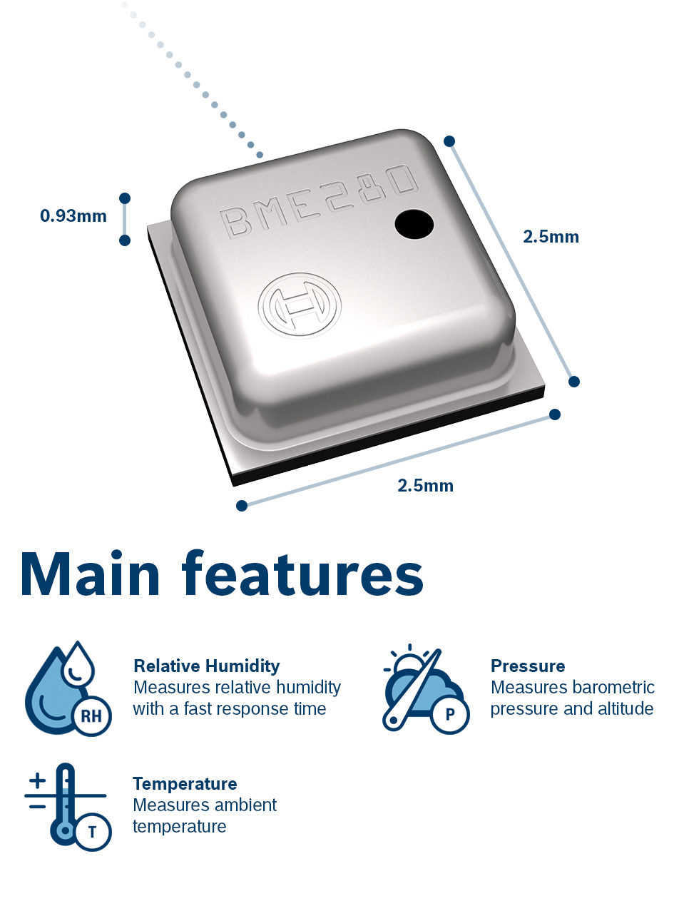
The BME280 is an integrated environmental sensor developed specifically for applications where the overall device size and low power consumption are key design constraints. It combines individual high linearity, high accuracy sensors for pressure, humidity and temperature, with an I2C/SPI interface for communication with MCUs. It is designed for low current consumption (3.6 μA @1Hz), long term stability and high EMC robustness.

The humidity sensor embedded in the BME280 features an extremely fast response time to support performance requirements for new applications such as context awareness, and high accuracy over a wide temperature range. The embedded pressure sensor is an absolute barometric pressure sensor with superb accuracy and resolution with very low noise. The integrated temperature sensor was designed to be used for temperature compensation of the pressure and humidity sensors, but can also be used for estimating ambient temperature with high resolution and low noise.

BME280 supports divers operating ranges which makes it flexible and super useful for applications including;

  • Context awareness, e.g. skin detection, room change detection
  • Fitness monitoring / well-being
  • Warning regarding dryness or high temperatures
  • Measurement of volume and air flow
  • Home automation control
  •  Control heating, ventilation, air conditioning (HVAC)
  • Internet of things
  • GPS enhancement (e.g. time-to-first-fix improvement, dead reckoning, slope detection)
  • Indoor navigation (change of floor detection, elevator detection)
  • Outdoor navigation, leisure and sports applications
  • Weather forecast
  •  Vertical velocity indication (rise/sink speed)

For today’s tutorial however, we will use it to simply obtain temperature, pressure and humidity data to be displayed on adafruit’s 128×64 OLED display. At the end of today’s tutorial, you would know how to use the BME280 and an OLED display with an Arduino Board.

Required Components

The following components are required to build this project;
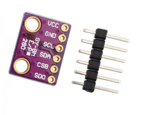
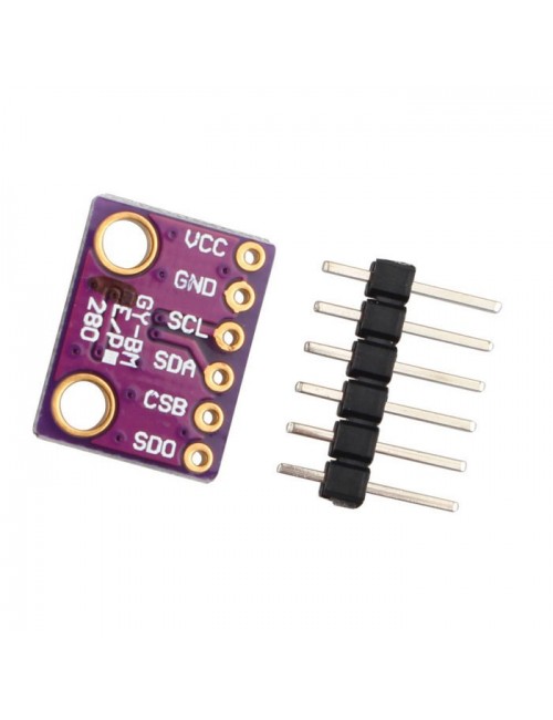
  1. GY-BME280 Sensor 
  2. Arduino UNO
  3. OLED 128*64 Display
  4. Breadboard
  5. Jumpers

As usual, the exact version of these components, used for this tutorial can be purchased via the attached links.

Schematics

The schematic for today’s project is relatively easy. The BME280 and the OLED display are both I2C based devices, as such, they will be connected to the same pins on the Arduino bus. Connect the components as shown in the schematics below.

Schematics

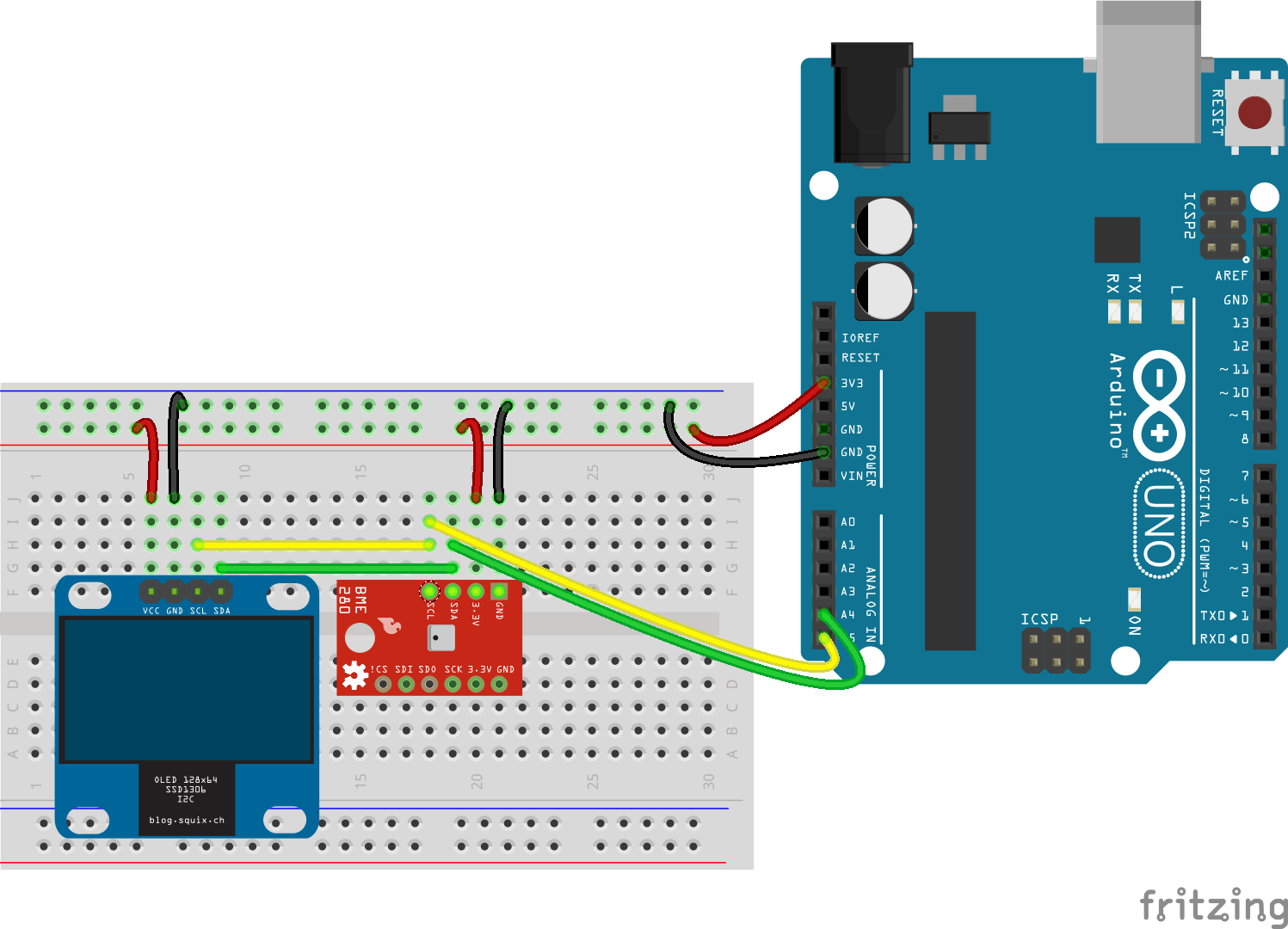
To show how the devices connect pin to pin, a map is shown below;

OLED – Arduino

SCL - A5
SDA - A4
VCC - 3.3v
GND - GND

BME280 – Arduino

SCL - A5
SDA - A4
VCC - 3.3v
GND - GND

Ensure the connections are properly done before proceeding to the next section.

Code

With the connections done, its now time to program the Arduino. Our goal for today’s project, as described in the introduction, is to simply measure the temperature, humidity, and pressure of the environment and display on the OLED display. To achieve this, we will use three major libraries; the adafruit BME280 library, the Adafruit SH1106 library, and the GFX library.  The BME280 library helps to easily interface with the BME280 sensor while the GFX and SH1106 libraries help interface with the OLED display. The libraries can all be installed via the Arduino IDE library manager.

The algorithm for the code is quite simple; Initialize the BME280, obtain readings for each of the parameters and display on the OLED.

To do a breakdown of the code, we start as usual, by including the libraries that will be used. In addition to the three libraries mentioned earlier, we will use a fonts library for better user experience.

#include <Adafruit_BME280.h>
#include <Adafruit_SH1106.h>
#include <Adafruit_GFX.h>
#include <Fonts/FreeSerif9pt7b.h>

With that done, define the OLED_RESET pin, create an instance of the SH11o6 class specifying the OLED_RESET variable as an argument and create an instance of the BME280 class. This will be used to communicate with the BME280 sensor over I2C.

#define OLED_RESET 4
Adafruit_SH1106 display(OLED_RESET);
Adafruit_BME280 bme;

With this done, we then proceed to the setup() function. We start the function by initializing the serial monitor with baudrate at 9600, then initialize the display using the display.begin() function with the I2C address of the OLED display(0x3C) as an argument. This is then followed up with the display.setFont() function to set the font after which the display is cleared.

void setup() 
{
  Serial.begin(9600);
  display.begin(SH1106_SWITCHCAPVCC, 0x3C);
  display.setFont(&FreeSerif9pt7b);
  display.display();
  delay(2000);
  display.clearDisplay();

To wrap up the setup() function, the BME280 is also initialized with the I2C address. the function is initialized such that it stays in a perpetual while loop if the initialization fails.

if (!bme.begin(0x76)) 
  {
          Serial.println("Could not find a valid BME280 sensor, check wiring!");
          while (1);
        }
}

The I2C address of each of the components, if not written in its datasheet, can be obtained by scanning the I2C line using the method described on the Arduino website.

Next, we write the void loop() function. We start by clearing the display using the display.clearDisplay() function after which, for each of the parameters, the value is read using the corresponding function; i.e bme.readTemperature() for temperature, bme.readPressure for pressure, and bme.readHumidity for humidity and displayed on the serial monitor and the OLED display.

void loop() 
{
  display.clearDisplay();
  
  // display Temperature
  Serial.print("Temperature = ");
  Serial.print(bme.readTemperature()); //prints in *C
  //Serial.print(bme.readTemperature() * 9 / 5 + 32); //prints in *F
  Serial.println("*C"); 
  display.setTextSize(1);
  display.setTextColor(WHITE);
  display.setCursor(0,15);
  display.print("Temp:");
  display.print((int)bme.readTemperature()); //prints in *C
  //display.print(bme.readTemperature() * 9 / 5 + 32); //prints in *F
  display.println("*C");
  display.display();
 
  //display pressure
  Serial.print("Pressure = ");
  Serial.print(bme.readPressure()/100.0F);
  Serial.println("hPa");
  display.setTextSize(1);
  display.setTextColor(WHITE);
  display.print("Press:");
  display.print(bme.readPressure()/100.0F);
  display.println("Pa");
  display.display();
  
  // display humidity
  Serial.print("Humidity = ");
  Serial.print(bme.readHumidity());
  Serial.println("%");
  display.setTextSize(1);
  display.setTextColor(WHITE);
  display.print("Hum:");
  display.print((int)bme.readHumidity());
  display.println("%");
  display.display();
  Serial.println();
  delay(1000);
}

The complete code for the project is available below and attached under the download section.

#include <Adafruit_BME280.h>
#include <Adafruit_SH1106.h>
#include <Adafruit_GFX.h>
#include <Fonts/FreeSerif9pt7b.h>

#define OLED_RESET 4
Adafruit_SH1106 display(OLED_RESET);
Adafruit_BME280 bme;

void setup() 
{
  Serial.begin(9600);
  display.begin(SH1106_SWITCHCAPVCC, 0x3C);
  display.setFont(&FreeSerif9pt7b);
  display.display();
  delay(2000);
  display.clearDisplay();
  if (!bme.begin(0x76)) 
  {
          Serial.println("Could not find a valid BME280 sensor, check wiring!");
          while (1);
        }
}

void loop() 
{
  display.clearDisplay();
  
  Serial.print("Temperature = ");
  Serial.print(bme.readTemperature()); //prints in *C
  //Serial.print(bme.readTemperature() * 9 / 5 + 32); //prints in *F
  Serial.println("*C"); 
  display.setTextSize(1);
  display.setTextColor(WHITE);
  display.setCursor(0,15);
  display.print("Temp:");
  display.print((int)bme.readTemperature()); //prints in *C
  //display.print(bme.readTemperature() * 9 / 5 + 32); //prints in *F
  display.println("*C");
  display.display();
  

  Serial.print("Pressure = ");
  Serial.print(bme.readPressure()/100.0F);
  Serial.println("hPa");
  display.setTextSize(1);
  display.setTextColor(WHITE);
  display.print("Press:");
  display.print(bme.readPressure()/100.0F);
  display.println("Pa");
  display.display();
  
  Serial.print("Humidity = ");
  Serial.print(bme.readHumidity());
  Serial.println("%");
  display.setTextSize(1);
  display.setTextColor(WHITE);
  display.print("Hum:");
  display.print((int)bme.readHumidity());
  display.println("%");
  display.display();
  Serial.println();
  delay(1000);
}

Demo

Go over the connections once again to ensure you connected everything properly. With that done, copy the code, paste in the Arduino IDE and upload to the Arduino board. You should see the display comes alive as shown in the image below.
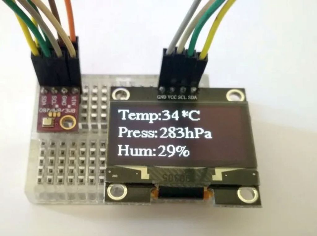
Credit: WolfxPac

Works right?

While this is a simple example of what’s is possible with the BME280, by going through the list of applications listed during the introduction, you can begin to imagine the amount of complex problems that can be solved using this sensor.

That’s all for this tutorial guys, thanks for following. Feel free to hit me up via the comment section if you have with all questions you might have about today’s tutorial.

emUSB-Device Video – Easily transmit video via USB

SEGGER introduces video class (UVC) support for emUSB-Device. An Embedded System with a USB device interface can now enumerate as a video camera. Once connected to a Host (Windows, Mac, Linux or Tablet), it is recognized as a camera. Video content can come from a live camera feed, a prerecorded video, or can be generated dynamically by using a graphics library such as SEGGER emWin. The ability to use a host as pluggable display does not cost more than the USB connector. No drivers on the host side are required.

Easily transmit video via USB. Send video data to the host. Simple and driverless! Plug-and-play on any operating system.

  • USB Video Device class (UVC) V1.1 implementation.
  • Send video to the host
  • Cross-platform, no drivers needed on Linux, macOS or Windows
  • High performance
  • Small footprint

Typical application examples include digital still cameras, video cameras, webcams, and all other devices that play instructional videos or provide animated video content. It can also be used for “headless” devices, that do not have their own display. There are primarily 2 types of applications: systems which only rarely need a display, such as engines or solar inverters, and systems with separate display units, such as washing machines, where the main processor controls the machine and is connected to a host showing the video on a display.

The video class is a component of SEGGER’s high performance USB stack emUSB-Device. emUSB-Device is specifically designed for Embedded Systems. It runs on any microcontroller and is platform-independent. The flexible device stack enables the creation of multi-class devices using nearly any combination of the available USB classes. emUSB-Device provides classes for Media Transfer Protocol, Mass Storage Device, MSD-CDROM, audio, video, Human Interface Device, CDC-ACM (Serial port communication), IP-over-USB, and printers. It also supports a custom communication interface using bulk transfer for easy and fast communication without protocol overhead. The emUSB-Device is fully compliant with USB standards.

SEGGER Evaluation Software for SEGGER emPower

To access more information on SEGGER’s emUSB-Device Video component please visit: https://www.segger.com/products/connectivity/emusb-device/add-ons/usb-video/

Full emUSB-Device product specifications are available at:

https://www.segger.com/products/connectivity/emusb-device/

ST releases ROM-Based GNSS module

Designed for mass-market tracking and navigation applications, the Teseo-LIV3R ROM-based module, has full GNSS algorithm capability for cost-conscious tracking and navigation devices, says ST Microelectronics.

The GNSS module provides odometer functionality with three trip counters and reached-distance alert, along with geo-fencing capabilities with up to eight configurable circles and crossing-circles alarm. Support for real-time assisted GNSS with free server access ensures uninterrupted positioning data for dependable navigation.

Simultaneous tracking of GPS, Glonass, Beidou, and QZSS constellations, with Satellite-Based Augmentation System (S-BAS) and (Radio Technical Commission for Maritime Services) RTCM V3.1 differential positioning ensures accuracy to within 1.5m (50 per cent Circular Error Probability (CEP). Tracking sensitivity of -163dBm and time-to-first-fix faster than one second ensure high performance for demanding applications.  The module responds to proprietary National Marine Electronics Association (NMEA) commands.

Teseo-LIV3R can be used for battery-sensitive applications as it has scalable power consumption according to accuracy, average current, and frequency of fixes, a sub-15µA standby mode with RTC backup, and support for low-power modes, including continuous-fix with adaptive and power-saving cycled modes, periodic-fix with GPS only, and fix-on-demand with the device in permanent standby.

The module is FCC-certified and is supported by the STM32 Open Development Environment. STM32 applications for advanced geolocation, smart tracking, and server-assisted GNSS are available and the EVB-LIV3x evaluation board and X-Nucleo-GNSS1A1 expansion board are also available for hardware development. The Teseo Suite PC tool helps configure settings and fine-tune performance.

The 9.7mm x 10.1mm LCC18 module is in production now. http://www.st.com

NANO²® High-Current Subminiature Fuse – 456SD Series

Littelfuse’s small sized, surface-mountable high-current fuse provides surge current protection.

Littelfuse’s 456SD series NANO² fuse is a small sized, surface-mountable high-current fuse which provides over current and excessive surge current protection for applications operating at high current in a limited space.

Such applications are mostly served today through a single large-sized high-current industrial type fuse or in some cases, parallel configuration of lower amperage SMD fuses. The 456SD 50 A series fuse gives the option of a single fuse solution for protection for such application requirements.

Features

  • Available in ratings of 40 A to 50 A
  • High interrupting rating: 600 A at 75 VDC
  • Very low cold resistance, temperature rise, and voltage drop
  • High inrush/surge current withstand capability
  • Surface mountable high-current fuse
  • Single fuse solution for high-current applications
  • Suitable for a wide variety of voltage requirements and applications
  • Enhances power efficiency
  • Avoids nuisance opening due to high inrush and surge current inherent in the system
  • Compatible with high-volume assembly requirements

Applications

  • Voltage regulator module for PC servers
  • Cooling fan system for PC servers
  • Storage system power
  • Base-station power supplies
  • Power tools

more information on www.littelfuse.com

VEML6035 Digital Light Sensor operates via simple I²C

Vishay’s low-power, high-sensitivity, ambient light sensor operates via simple I²C command

Vishay’s VEML6035 is a 16-bit, low-power, high-sensitivity CMOS ambient light sensor operated via a simple I²C command. The sensor offers an active interruption feature that is triggered outside of the threshold window settings, thereby eliminating loading on the host. The active average power consumption is approximately 300 μW.

VEML6035 incorporates a photodiode, amplifiers, and analog/digital circuits in a single chip. Vishay’s patented Filtron™ technology, a wafer-level optical filter, provides the best spectral sensitivity to match human eye responses. The sensor has excellent temperature compensation to maintain output stability under changing temperatures and its refresh rate setting does not need an external RC low-pass filter. There is a programmable shutdown mode which reduces current consumption.

Features

  • Package type: surface-mount
  • Dimensions (L x W x H): 2.0 mm x 2.0 mm x 0.4 mm
  • Integrated modules: ambient light sensor (ALS)
  • Supply voltage range VDD: 1.7 V to 3.6 V
  • Communication via I²C interface
  • I²C bus H-level range: 1.7 V to 3.6 V
  • Floor life: 168 h, MSL 3, according to J-STD-020
  • Low standby current consumption: 0.5 μA (typ.)

Applications

  • Ambient light sensor for mobile devices (e.g. smart phones, touch phones, PDA, GPS) for backlight dimming even under tinted glass
  • Ambient light sensor for industrial on-/off-lighting operation
  • Optical switch for consumer, computing, and industrial devices and displays

more information on www.vishay.com

Perf-V FPGA Based RISC-V Development Board

The Perf-V is an FPGA based development board designed for RISC-V opensource community by PerfXLab. It incorporates various peripheral chips and offers many interfaces. Perf-V has great flexibility and transplant multiple architectures. Some RISC-V development boards with silicon featuring RISC-V instruction set already exist, such as SiFive’s HiFive1 or Kendry KD233 board. One good thing about RISC-V is that it allows a user to customize the instructions set, and if you are up for that, an FPGA board provides the flexibility you need. The board uses Xilinx Artix-7 FPGA, Vivado software development, and it is designed for the RISC-V open source community and FPGA learning enthusiasts design development board.

The Perf-V incorporates a variety of outlying chips to enable a rich set of peripheral interfaces, including PMOD, Arduino, JTAG, UART interfaces, and high-speed interfaces for expansion of HDMI, VGA, USB2.0/3.0, camera, Bluetooth, expansion boards, etc. Strong flexibility. Due to its self-developed smart car, the Perf-V can use mobile phone Bluetooth to control the movement of the car and can realize automatic tracing and obstacle avoidance functions. This is quite an impressive function for me. Perf-V successfully ports a variant of RISC-V architectures, enabling a solid experimental platform for RISC-V processor design and FPGA product development, and is the preferred hardware for learning, scientific research, project development, and DEMO solutions.

The Perf-V provides a variety of modules available for selecting powerful, rich learning materials, complete experimental routines which are cost-effective. If you will like to purchase the board, you can do so by getting a $79 kit with the board and a USB burner / FPGA USB cable. A download page is available, but only with hardware documentation like datasheets and PCB layout (PDF), but nothing entirely about RISC-V.

The specification listed for the Perf-V board include

  • FPGA – Xilinx Artix-7 XC7A35T-1FTG256C with 33280 Logic Cells, 90 DSP, 41600 CLBs, 1800 Kbit Block RAM, and 5 CMTs; Optional FPGAs up to Xilinx XC7A100T with 101,440 logic cells
  • System Memory – 256MB DDR3 (16Megx16x8Banks)
  • Storage – 8MB FPGA FLASH, 8MB RISC-V flash
  • Expansions: Arduino compatible headers, 1x PMOD connector, “High-speed interface” for expansion of HDMI, VGA, USB2.0/3.0, camera, Bluetooth, expansion boards, etc
  • Debugging — User JTAG/UART interface
  • Misc – Power & user LEDs; 6x soft-touch buttons; power key
  • Power Supply – Via power barrel jack

For more information, visit the forums which are in Chinese, and download page too.

Programmable USB Hub has I2C, GPIO and SPI

A USB hub that’s also a dev board and an I2C, GPIO, and SPI bridge

In addition to being a 4-port USB 2 High-Speed hub, this Programmable USB hub is also:

  • A CircuitPython based development board.
  • A bridge between your computer and I2C (via Sparkfun Qwiic connectors), GPIO, and SPI (via its mikroBUS header).
  • A power supply, providing 6 A of 5 V power to downstream devices and 13 mA resolution monitoring (per-port). Port power is individually limitable and switchable.
  • A USB to TTL Serial adapter.
  • A flexible embedded electronics test and development tool. USB data pairs are individually switchable, allowing you to emulate device removal and insertion via software.
  • Mountable.
  • Functionally flexible. Open source python drivers on the upstream host and Python firmware on the internal MCU allow the behavior of this USB hub to be easily changed to suit your application and environment.

The Capable Robot Programmable USB hub is housed in a robust extruded aluminum enclosure.

Internally mounted LED light pipes direct status information from 10 RGB LEDs to the front panel for easy observation of hub state.

The rear of the enclosure exposes the upstream USB connection and a USB port to re-program and communicate with the internal MCU. Also exposed are two I2C buses (via Sparkfun Qwiic connectors), the Programmable USB hub’s UART, and 2x GPIO. Input power is provided to the hub by a locking Molex connector.

Features and Specifications

  • USB2 High-Speed Hub
    • 4x USB2 High Speed (480 mbps) downstream ports
    • 1x USB2 High Speed (480 mbps) upstream port
    • 5th endpoint on USB hub exposes I2C, SPI, UART, and 2x GPIO
    • Data lines to each USB port can be disconnected via software commands. This allows errant USB devices to be “unplugged” virtually and re-enumerated.
    • USB digital signals can be boosted to help drive long cables.
  • Power Monitoring & Control
    • 5 V power on each downstream port can be individually turned on and off
    • Monitor the power consumed by each port at up to 200 Hz at a resolution of 13 mA
    • Adjustable (per-port) current limits between 0.5 A and 2.6 A
    • Onboard regulator supports 12 V to 24 V power input and generates 6 A of 5 V power for downstream USB devices; both voltages can be monitored by the internal MCU. No power is drawn from the upstream USB port.
    • Input power is protected from over-voltage events and reverse-polarity connection.
  • Physical IO
    • mikroBUS header to add additional sensors and connectivity. Solder jumpers allow the UART and SPI pins to connect to either the USB hub or the MCU.
    • JST GH connector with UART and 2x GPIO, controlled by the USB hub.
    • 2x Sparkfun Qwiic connectors enable easy attachment of I2C sensors to the USB hub or to the internal MCU.
    • 5x RGB status LEDs to visualize port power draw
    • 5x RGB status LEDs to visualize port connection types

The project is live on Crowdsupply.com and has 49 days left with pledges starting at $200.

LED Lighting Effects Generator using PIC16F886

This project generates 8 different LED-lighting patterns (Visual Effects) and is based on PIC16F886. The project demonstrates different chasing effects being generated using 20 SMD LEDs and  speed of LED-lighting moving is adjustable with the help of the on board trimmer potentiometer. 8 patters can be set using 3 on board PCB jumpers. Circuit consists of PIC16F886 micro-controller from Microchip and 20 SMD LEDs. Circuit works with 5V DC, Trimmer potentiometer provided to adjust speed of sequence.

Features

  • Supply 5V DC
  • 8 Different Patters Possible ( LED-Lighting Sequence)
  • Chasing speed adjustable

LED Lighting Effects Generator using PIC16F886 – [Link]

LED Lighting Effects Generator using PIC16F886

This project generates 8 different LED-lighting patterns (Visual Effects) and is based on PIC16F886. The project demonstrates different chasing effects being generated using 20 SMD LEDs and  speed of LED-lighting moving is adjustable with the help of the on board trimmer potentiometer. 8 patters can be set using 3 on board PCB jumpers. Circuit consists of PIC16F886 micro-controller from Microchip and 20 SMD LEDs. Circuit works with 5V DC, Trimmer potentiometer provided to adjust speed of sequence.

Features

  • Supply 5V DC
  • 8 Different Patters Possible ( LED-Lighting Sequence)
  • Chasing speed adjustable

Schematic

Parts List

Connections

Jumper Settings

Photos

Video

PIC16F886 Datasheet

Commell LE-37M SBC Taps 8th Gen “Coffee Lake” clocked up to 4.3Ghz

Commell has launched a 3.5-inch “LE-37M” SBC that taps Intel’s 8th Gen H-series CPUs, and features triple displays, 4x USB 3.1, 2x SATA III, 2x GbE, and mini-PCIe and M.2 expansion. Commell has released a number of Intel’s 8th Gen “Coffee Lake” products and they launched the LV-67X industrial Mini-ITX board last August and followed up with a 3.5-inch LS-37L SBC that also supports up to 65W TDP Coffee Lake S-series chips via an FCLGA1151 socket. The LE-37M has a few new features and an FCBGA1440 socket which supports Coffee Lake H-series with more embedded-friendly 45W TDPs.

Commell offers two variants of the SBC, a LE-37M5 SKU with the quad-core, 8-thread Core i5-8400H clocked at 2.4GHz/4.2GHz and a LE-37M7 with the hexa-core, 12-thread Core i7-8850H clocked at 2.6GHz/4.3GHz. A QM370 chipset is present in the SBC, instead of the newer Q370 present on the S-series boards. Just like the earlier Commell SBCs, the LE-37M is available with Windows drivers but can support Linux as mentioned in the manual. The LE-37M is developed for imaging, machine vision, infotainment, medical, and gaming machine applications.

The LE-37M offers twice the RAM as the LS-37L with up to 32GB of dual-channel, 2666MHz DDR4. The LE-37M is also equipped with 2x GbE and 4x USB 3.1 ports, 2x SATA III ports and a mini-PCIe slot with mSATA and PCIe support. The SIM slot has been replaced with an M.2 E-key slot for general-purpose expansion. The LE-37M offers triple display support, but with a slightly different feature set. Instead of a header, there’s a new coastline VGA port in addition to the HDMI port and headers for DVI, LVDS, and an LCD inverter. The LE-37M offers you a choice of Display Port or a second VGA or LVDS header (LS-37MT5 or LS-37MT7 SKUs).

The VGA port substitutes the LS-37L’s DB9 COM port, and instead of 4x RS232 headers you now get two. Available also are headers for 2x RS232/422/485, 4x USB 2.0, and HD audio, GPIO, PS/2, and SMBus. The system offers a 0 to 60°C range and has a wider 9-35V power input. No pricing or availability information is provided for the LE-37M.

Specifications listed for the LE-37M include:

  • Processor — Intel 8th Gen “Coffee Lake” H-series with FCBGA1440 socket, QM370 chipset, Intel UHD Graphics, 45W TDP, Core i5-8400H (4x core, 8x thread @ 2.4GHz/4.2GHz), Core i5-8400H (6x core, 12x thread @ 2.6GHz/4.3GHz)
  • Memory — Up to 32GB DDR4 (2666MHz) via 2x SODIMMs
  • Storage — 2x SATA 3.0 with RAID 0, 1 and Intel Rapid Storage Technology.; mSATA via mini-PCIe
  • Display/media: HDMI port, VGA port, DisplayPort or on LS-37MT5 or LS-37MT7 SKUs, a second VGA or LVDS header, LVDS, DVI headers, LCD inverter, Triple display, and 4K support, Audio mic-in/line-in and line-out header (Realtek ALC262)
  • Networking — 2x Gigabit Ethernet ports (Intel I211AT and 1219LM); LM port supports iAMT 12.0
  • Other I/O: 4x USB 3.1 Gen 2 ports, 4x USB 2.0, 2x RS-232, 2x RS232/422/485, 8-bit GPIO, SMBus, PS/2
  • Expansion — Mini-PCIe slot (mSATA/PCIe); M.2 E-key
  • Other features — Watchdog; RTC with battery
  • Power — 9-35V DC input
  • Operating temperatures — 0 to 60°C
  • Dimensions — 146 x 101mm (“3.5-inch form factor”)
  • Operating system — Windows 10 drivers; supports Linux

More information can be found in Commell’s LE-37M announcement and product page.

TOP PCB Companies