Thermal Camera records infrared images that the human eyes can’t see which can give it a niche use for different applications. A thermal camera is great of observing the temperature variation of an object and it has application in the health, security, electronics, animal and several industries. The most critical parameter for the thermal camera is its temperature sensitivity, the more sensitive a thermal camera is, the best the quality of the image, which usually translates to better measurement.
HT-102 Thermal Camera
With a thermal camera, you can see things at night like people moving around because they have apparent temperature variation of body temperature. One exciting application of thermal imaging I like is the ability to see what may be happened in”Past.” Thermal imaging of an object or place can give a hint of what might have happened at some time t – 1, for example, in a parking lot, thermal imaging of the cars will tell you which car was recently driven or if someone once moved around that place.
Although thermal imaging application sounds pretty cool, one of the challenges of using Thermal cameras is the relatively high cost of getting the cameras. The thermal cameras could cost up to thousands of dollars; they are usually expensive. One way to buy a lower cost thermal camera, is to get those that need to be used with a smartphone which does cost around $200 on Amazon. A very cheap one discovered is the HT-102 thermal camera designed to work with Android Phones.
HT-102 Thermal Camera
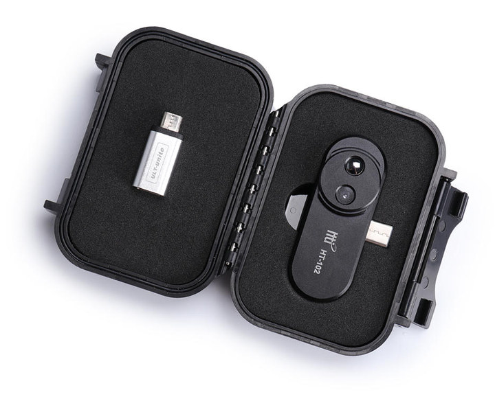
The HT-102 is a Chinese made thermal camera available for about $120 on Gearbest.The HT-102 thermal camera can be connected to your smartphone (Android supported) and used to take thermal imaging of the environment. Below are some of the device specifications:
Temperature Range – Operating: 0 to 35°C; storage: -20 to 60°C
The camera ships with an English user manual, a storage box, and a USB Type-C to Micro USB Adapter for phones without a USB-C port. The camera requires the Thermal Viewer app for Android to be able to be used and visualize the result. Below is a sample of the possible output you will get with the camera.
HT-102 Thermal Camera With Thermal Viewer App
Although, the HT-102 is a sizeable and low-budget thermal camera don’t expect it to stand toe to toe with higher end thermal cameras like those from FLIR cameras and others. HT-102 is a basic thermal camera to get started with loving thermal imaging. A quick search on Aliexpress also shows a similar like HT 102 that cost rough around $96.
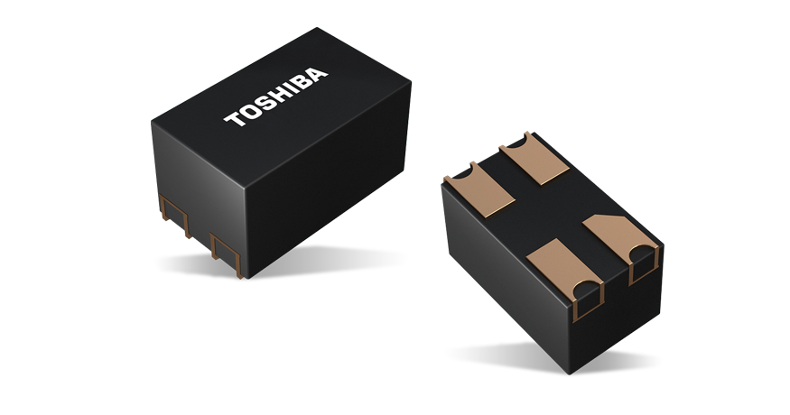
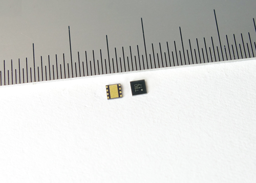
Toshiba Electronics Europe GmbH, the industry leader in the miniaturisation of cutting-edge photorelays, introduced a new family of five photorelays housed in one of the industry’s smallest package. The new devices are suited for use in automatic test equipment, memory testers, SoC/LSI testers and probe cards.
Both TLP34xxSRL devices and all three of the TLP34xxSRH series have input voltage driven characteristics. The TLP3406SRL and TLP3407SRL support a DC voltage range of 1.8V (typ.) to 3.3V (typ.), while TLP3406SRH, TLP3407SRH and TLP3412SRH support a DC voltage range of 3.3V (typ.) to 5V (typ.), characteristics that enhance compatibility with today’s low voltage FPGAs.
The new photorelays are housed in tiny S-VSONR4 (2.0mm x 1.45mm) packages and require a mounting space of just 2.9mm2, a footprint approximately 27% smaller than Toshiba’s previous generation VSONR4 (2.75mm x 1.45mm) package. In addition, all devices have a built-in input resistor, saving space by eliminating the need for an external resistor. The tiny packaging will allow engineers to design smaller test boards, especially probe cards. It also allows the number of photorelays on a board to be increased to achieve higher density solutions.
Despite their tiny package size, the new photorelays can drive large currents. The TLP3406SRx delivers up to 1.5A with an off-state voltage (VOFF) of 30V and an on-state resistance (Ron) of 0.2 Ω (max.) while the TLP3407SRx is capable of up to 1A with a VOFF of 60V and Ron of 0.3Ω. The TLP34012SRH can drive up to 0.4A (VOFF = 60V / Ron = 1.5Ω). This makes all the new devices highly suited to device power supply applications across a wide range of test equipment. All devices are guaranteed to work at operating temperatures up to 110℃ and provide 500Vrms of isolation.
Shipments of the new devices will begin immediately.
Follow the link below for more on Toshiba’s optical devices line-up:
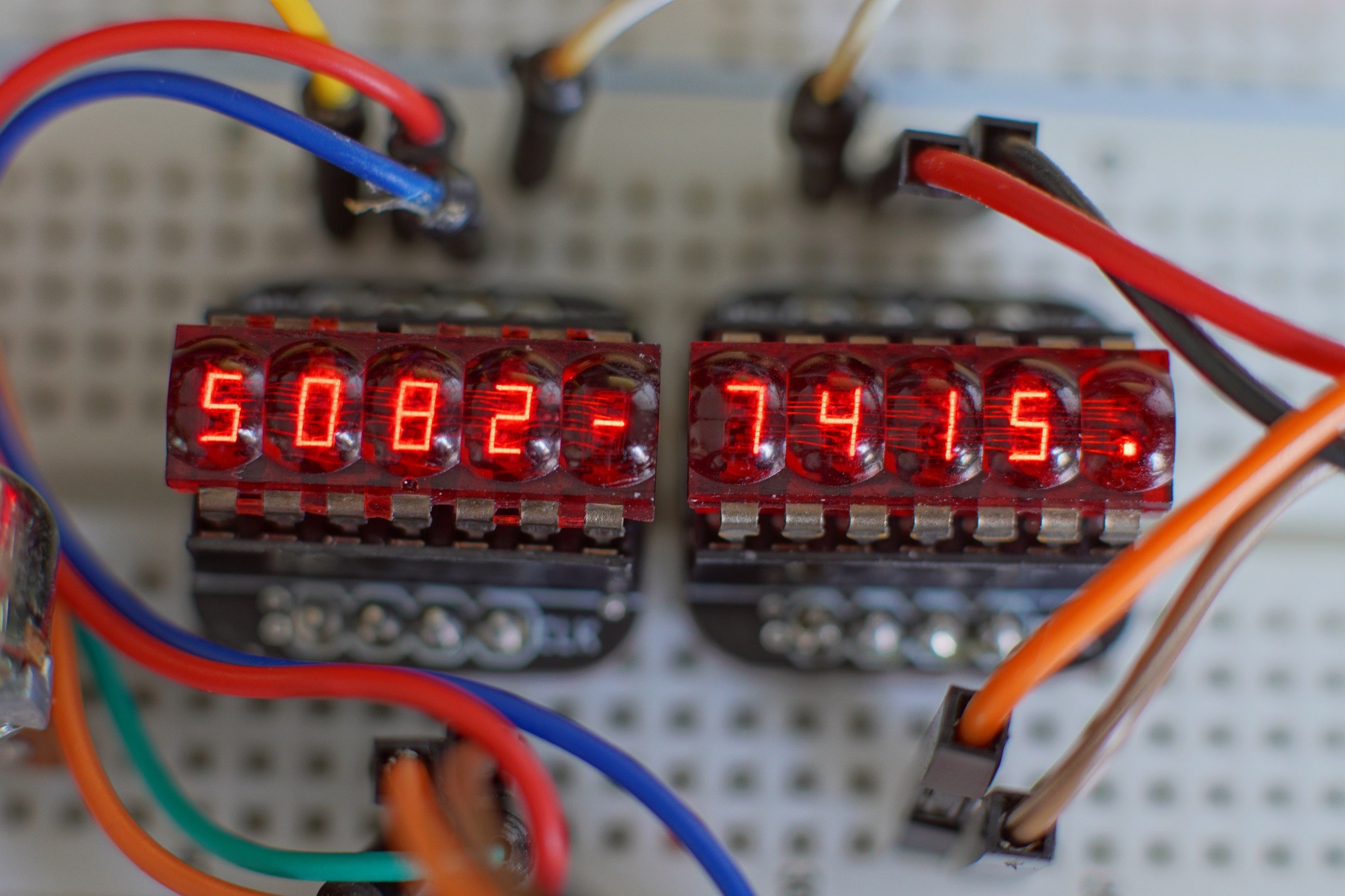
A small interface board for the legendary HP 5082-7415 and 7405 DIP bubble display. by Yannick (Gigawipf):
This project describes a breadboard friendly breakout board with 2 shift registers and resistors for these modules with dip socket to be gentle on these rare displays from the 70s. One shift register controls the anodes and one the cathodes like most modern 7 segment modules.
These rare 7 segment displays once used in HP calculators are still quite impressive if you are lucky enough to find some. Yes they are inefficient. But nothing compares to the deep red glow of those sharp and tiny GaAsP LED segments.
This interface board features 8 current limiting resistors for the segments and two tiny latched qfn shift registers. One for the anodes and one for the cathodes. This makes it simple to interface with modern microcontrollers (Example arduino sketch provided in files). The left one is a 7415 and the right one the 7405 with the centered dot.
IoT is now mainstream. It has gone beyond the buzzword it used to be and several tools are being made available to makers to facilitate the development of solutions based on it. One of the newest IoT platforms is the Arduino IoT Cloud developed by our good friends at Arduino.cc. Today we will examine how you can build projects that interact with the Arduino IoT Cloud, such as sending and receiving data.
The Arduino IoT Cloud is Arduino’s way of democratizing IoT development, making it easy for everyone to build internet of things applications. It provides the ability for IoT based devices to exchange data between each other and the cloud where further processing can be done and use the data to solve specific problems. The platform allows communication via a host of protocols including; HTTP REST API, MQTT, Command-Line Tools, Javascript, and Websockets. It features the typical “easy to use” nature of the Arduino and also features tools that make it capable of automatically generating the sketch/code for your device, which helps reduce development time from hours to minutes. In its typical open source nature and support for other clones, the Arduino IoT Cloud allows the connection of other Linux-based devices and boards to the platform.
Getting Started with the Arduino IoT Cloud – [Link]
IoT is now mainstream. It has gone beyond the buzzword it used to be and several tools are being made available to makers to facilitate the development of solutions based on it. One of the newest IoT platforms is the Arduino IoT Cloud developed by our good friends at Arduino.cc. Today we will examine how you can build projects that interact with the Arduino IoT Cloud, such as sending and receiving data.
The Arduino IoT Cloud is Arduino’s way of democratizing IoT development, making it easy for everyone to build internet of things applications. It provides the ability for IoT based devices to exchange data between each other and the cloud where further processing can be done and use the data to solve specific problems. The platform allows communication via a host of protocols including; HTTP REST API, MQTT,Command-Line Tools, Javascript, and Websockets. It features the typical “easy to use” nature of the Arduino and also features tools that make it capable of automatically generating the sketch/code for your device, which helps reduce development time from hours to minutes. In its typical open source nature and support for other clones, the Arduino IoT Cloud allows the connection of other Linux-based devices and boards to the platform.
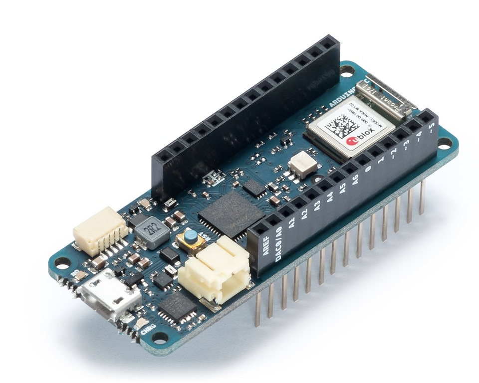
Arduino MKR WiFi 1010
At the center of today’s project is the Arduino MKR WiFi 1010. It is a significantly improved version of the MKR 1000 WiFi. It’s equipped with an ESP32 module made by U-BLOX. The board aims to speed up and simplify the prototyping of WiFi-based IoT applications thanks to the flexibility of the ESP32 module and its low power consumption.
The board is composed of three main blocks:
SAMD21 Cortex-M0+ 32bit Low Power ARM MCU
U-BLOX NINA-W10 Series Low Power 2.4GHz IEEE® 802.11 b/g/n Wi-Fi
ECC508 Crypto Authentication
The MKR WIFI 1010 includes a 32-bit computational power, the usual rich set of I/O interfaces associated with Arduino boards, and a low power Wi-Fi with a Cryptochip for secure communication using SHA-256 encryption. All these features can easily be programmed using Arduino Software (IDE) for code development and programming.
As a demo to show how the Arduino IoT cloud works, we will build a simple weather monitor. The device will obtain temperature, humidity, atmospheric pressure, and light intensity data from the environment using the Arduino MKR ENV shield and upload the data to the Arduino IoT Cloud every 2s. To provide an offline view of the data, we will use a 1.44 Adafruit TFT LCD display. You can check some of our past tutorials using the 1.44″ TFT display to better understands how it works.
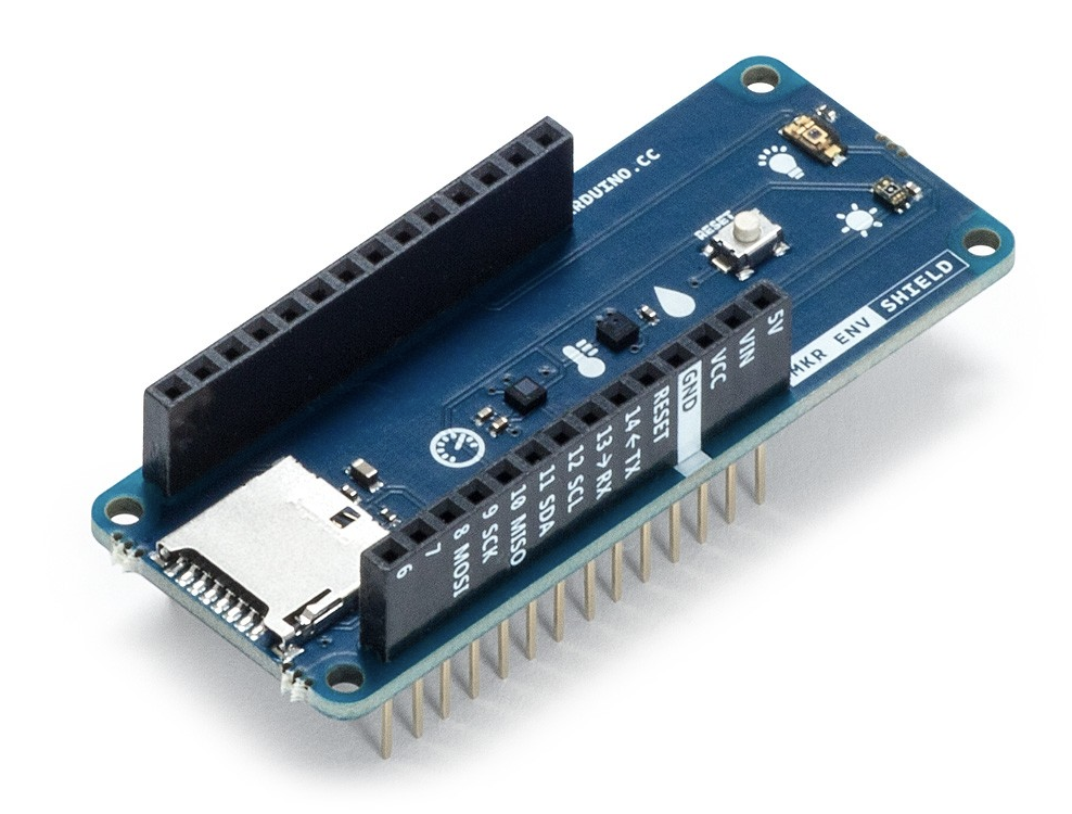
Arduino MKR ENV shield
The Arduino MKR ENV shield allows the MKR Arduino board series to acquire environmental data via a plethora of sensors built into the board. The inbuilt sensors include latest generation sensors for measuring;
To give you the ability to store data from the sensors, the ENV shield also has a slot for a microSD card onboard. We will use 4 out of the 5 sensors onboard the ENV Shield for today’s tutorial.
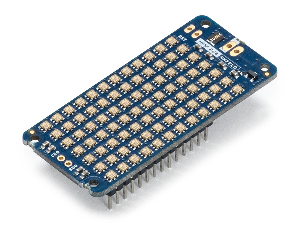
To demonstrate how to process/send data from the IoT cloud to devices, we will use the Arduino MKR RGB Shield to display the text “ON” or “OFF”, depending on the state of a button on the IoT Cloud.
Arduino MKR RGB Shield
The MKR RGB shield is the last “new” element for today’s project. The shield comprises an array of super bright LEDs which, with the use of a superb library, allows the display of static and scrolling text in minutes.
At the end of today’s tutorial, you would know how to work with the Arduino Create platform, build IoT devices based on the Arduino IoT Cloud, and work with the MKR WiFi 1010 Arduino board along with its accessories.
Required Components
The following components are required to replicate this project;
Arduino MKR WiFi 1010
Arduino MKR ENV Shield
Arduino MKR RGB Shield
Adafruit 1.44TFT Display
The components can all be bought from the Arduino store or from sellers on electronics components sales platforms like banggood, and Aliexpress.
Schematics
To make the project easier to follow and understand, we will break it down into two parts. The first part will entail how to send data to the Arduino IoT cloud while the second part will cover how to receive data from it.
Part 1 Schematics
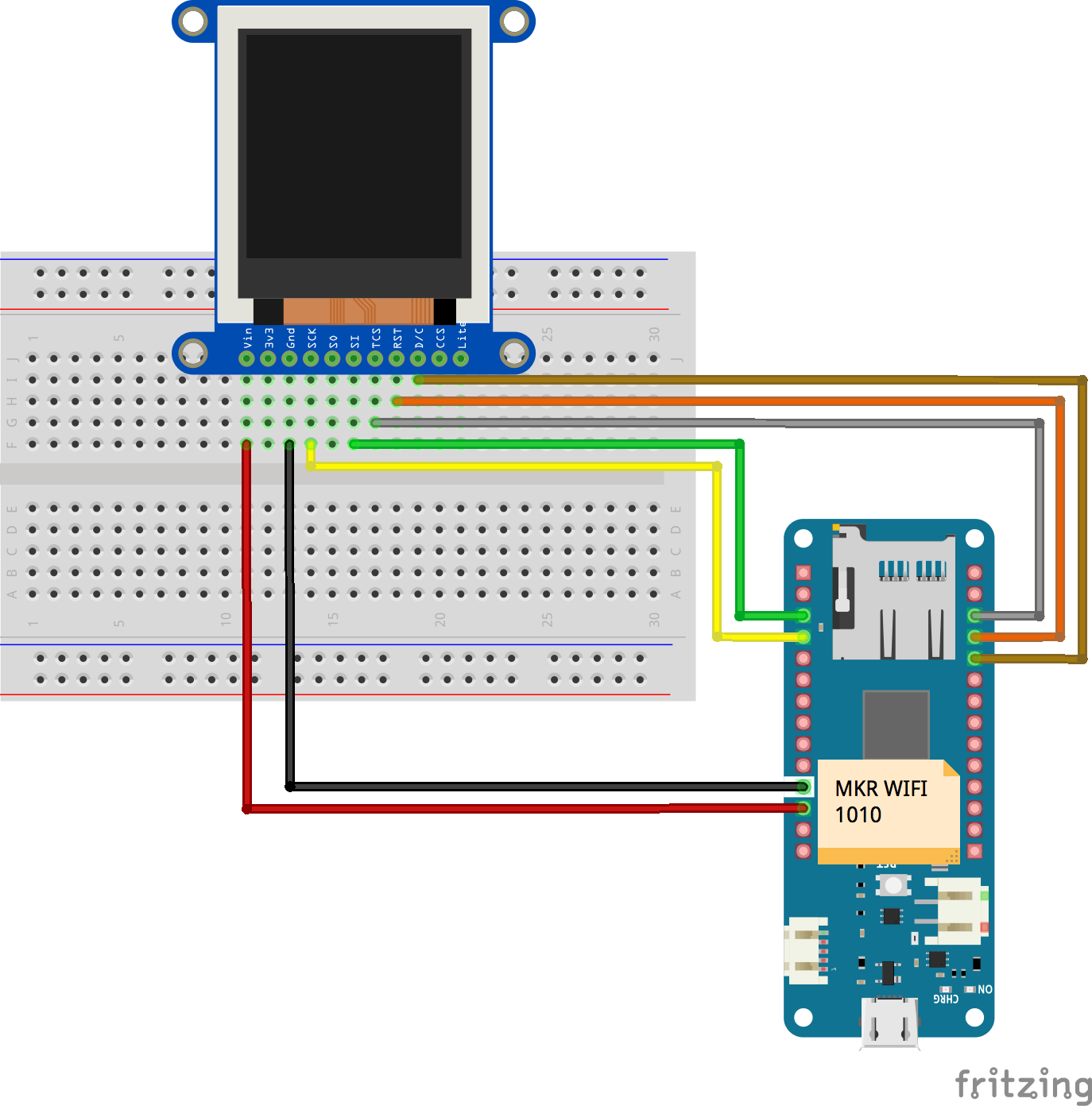
For the first part (sending data to the cloud), we will use the Arduino MKR WiFi 1010 board, the MKR ENV Shield, and the 1.44″ TFT Display. The MKR ENV Shield, like the name implies, comes as a shield which is going to be plugged on top the MKR WiFi 1010, leaving us with just the connections between the MKR WiFi 1010 and the 1.44″ TFT display. Connect them as shown in the fritzing schematics below.
Schematics
To make connections easier to follow, the pin to pin map of the connection between the MKR WiFi 1010 and the 1.44″ TFT is shown below.
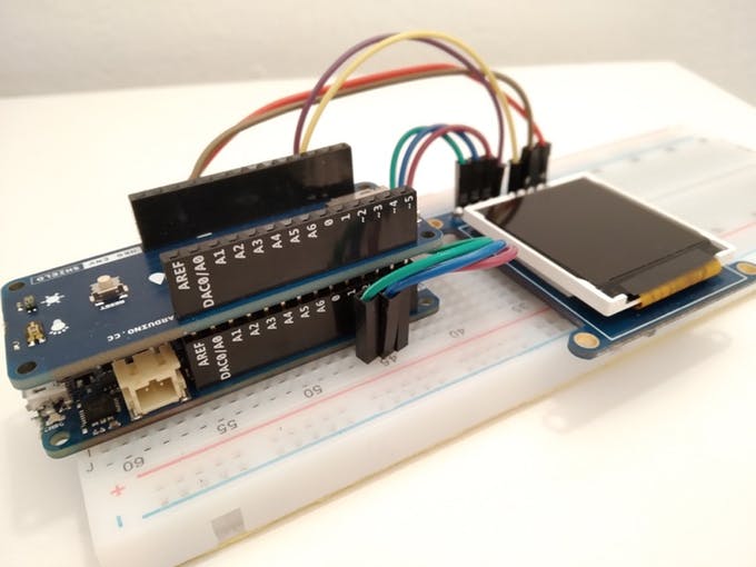
After connecting the components, your setup should look like the one in the image below.
Part 2 Schematics
For the second half of the project (Receiving Data from the cloud), we will use Arduino MKR WiFi 1010 and the Arduino MKR RGB Shield. While adjustments could be made to accommodate the sensors on the ENV shield, we will do it this way to keep things short and simple.
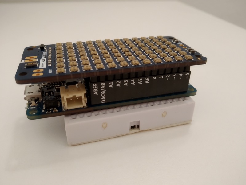
Just like the MKR ENV Shield, the RGB Shield, as the name implies also comes as a shield and should be plugged on the MKR WiFi 1010 as shown in the image below.
Since you will most likely use the same MKR WiFi 1010 for both parts, you can complete the code upload of one part before connecting the second part.
Programming
In contrast to what we used to, for today’s tutorial, we will not use the Arduino (offline) IDE software to write the code for our project. Instead, we will use the Arduino Create platform with the code for the project automatically generated by the Arduino IoT cloud.
Just like we did under the schematics, we will also split this into two parts. The first part will be for programming the board to send the data as we highlighted initially while the second part will be to receive data from the IoT Cloud and perform actions with it, which in this case is used to display ON/OFF on the RGB shield.
Programming Part 1
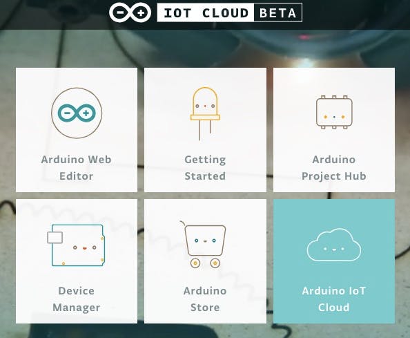
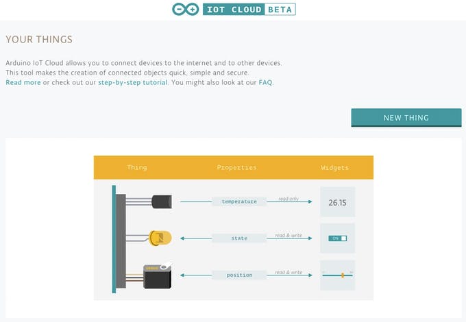
For the first part, We start by going to the Arduino IoT Cloud platform and selecting the -> Arduino IoT Cloud.
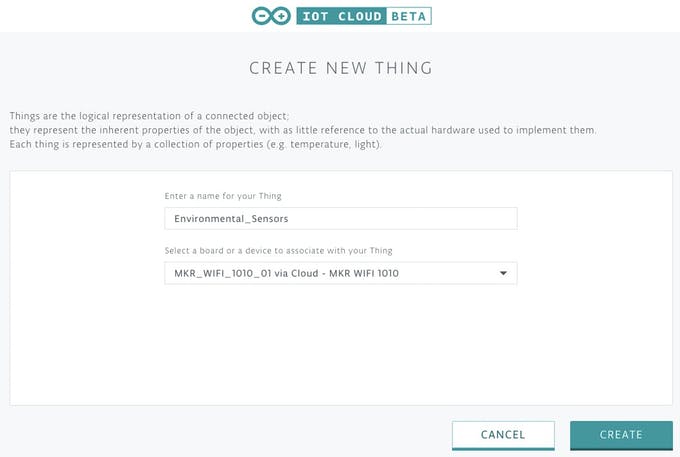
On the succeeding page, we select the “new thing” button which allows us to set up a new IoT device on the Cloud Platform.
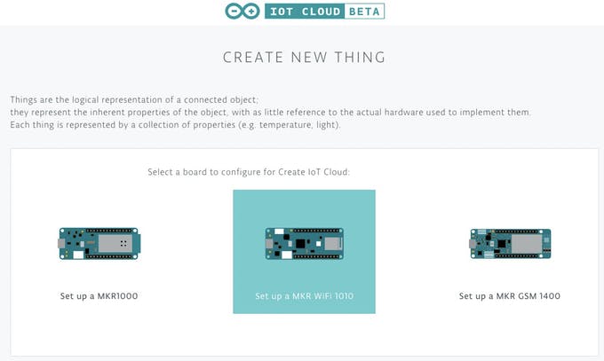
On the page that opens, select the board on which the “thing” is based, Which in our case is the Arduino MKR WiFi 1010.
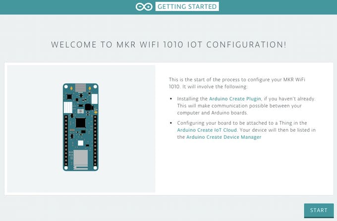
This launches the MKR 1010 configuration window. You will need to download and install the Arduino Create Plugin at this point if you don’t have it installed already. Click on the start button.
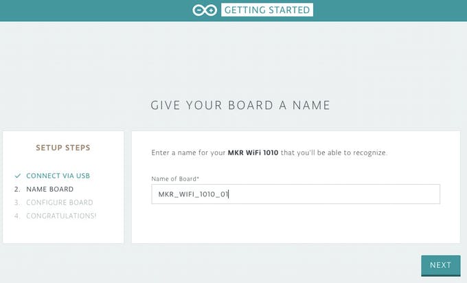
The system will instruct you to connect your board to your PC. As soon as this is done, if your installation of the Arduino Create plugin was successful, the board will appear under the board list like in the Image below. Rename the board to any name you like or just leave the default (not advisable for security reasons).
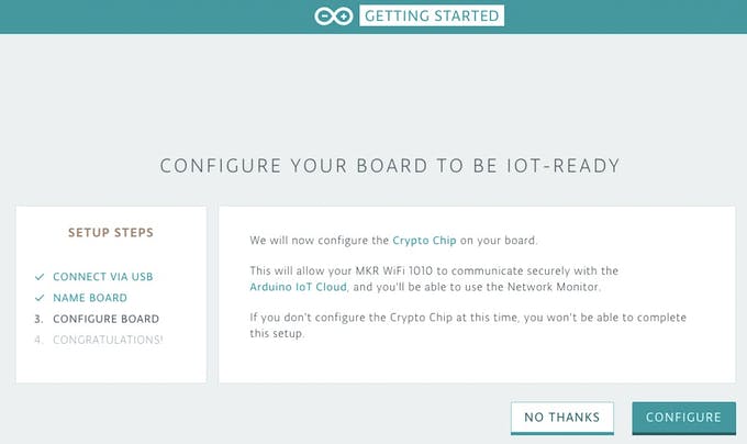
With that done, the next step is to configure the crypto chip on the board. This provides some sort of encrypted key specific to the board which allows the board to interact securely with the cloud. The setup will not be successful if you fail to go through this step.
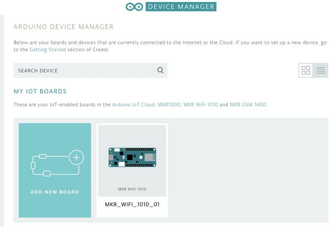
With that done, the board should now be visible in your Arduino Cloud device manager interface and we can now proceed to create/associate a thing with it.
Click on the board and create a new thing based on it.
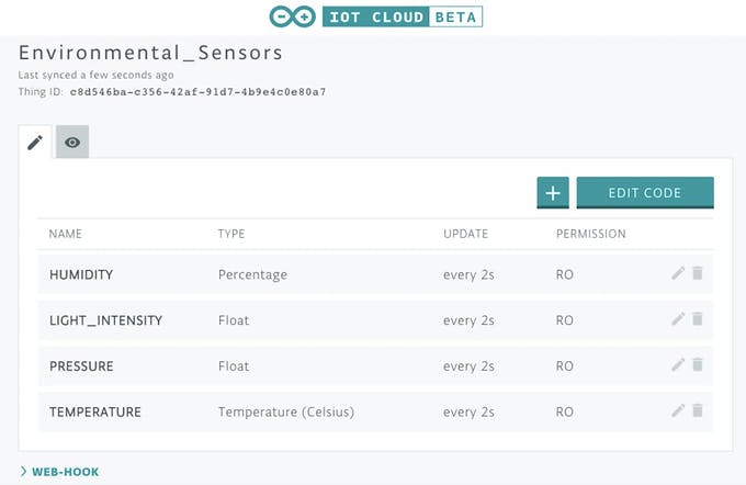
For each “thing” created on the Arduino IoT Cloud, you can define a couple of properties for the thing by clicking on the “+” sign in the things edit view. Properties represent specific data associated with your IoT Object and are defined with certain features including Data type, Update frequency and permissions which could be either be read-only or read&write. Read-only permissions means the values/state/content of that particular property cannot be edited from the cloud server and is thus ideal for holding sensor data, while the Read&Write on the other hand, is used when you want to be able to edit the state/value/content of a property from the IoT Cloud. Properties which involve sending data/commands from the cloud to the device are best defined using this permission.
For the first part of the project, we will attach 4 properties including; temperature, humidity, atmospheric pressure, and light intensity, to our “thing”. Each of these properties will hold the corresponding values from the sensors on the ENV Shield and will have read-only permission. Create the properties as shown in the example for the temperature property below.
Do the above for the remaining properties such that your “things property window”, looks like the image below.
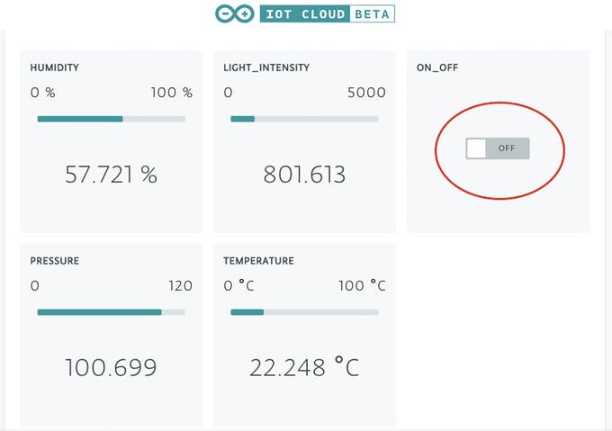
With this done, the four properties should now be reflected on your widget page but with no values, since we are yet to program the board.
Another good thing about the Arduino IoT cloud is its ability to autogenerate the code for your project based on your board type and the properties you selected for the “thing”. To autogenerate the sketch files, click on the “edit code” button. You should now be able to see the sketch and the other files that have been generated for the project. All we now need to do is to add the code for the TFT to the sketch and the credentials of our WiFi (SSID and Password) to the Arduino_secrets.h file.
While the code is autogenerated, to keep the tradition, I will try to explain it to make it easier to work with going forward.
The sketch starts with the inclusion of the libraries and header files that will be used. In addition to the libraries and header files in the autogenerated code, we will use the Adafruit GFX Library (Core graphics display library from Adafruit) and the Adafruit ST7735 Library (Hardware Specific library for ST7735 TFT Display).
After the above, we declare the pins of the Arduino to which the Chip Select(CS), Reset(RST) and DC pins of the TFT LCD are connected (as described under the schematics section).
Fllowed by the declaration of variables to hold the values from the sensors on the ENV shield, alongside a variable to hold the last time the device connected to the cloud, and another to hold the interval at which data will be posted.
///////////////////////////
float _temperature = 0;
float _humidity = 0;
float _pressure = 0;
float _lux = 0;
unsigned long lastConnectionTime = 0; // last time you connected to the server, in milliseconds
const unsigned long postingInterval = 2000; // delay between updates, in milliseconds
With this done, we move to the void setup() function. We start by initializing serial communication, setting the baud rate to 9600 and then initializing the parameters defined in the thingproperties.h header file with the initProperties() function.
void setup() {
// Initialize serial and wait for port to open:
Serial.begin(9600);
// This delay gives the chance to wait for a Serial Monitor without blocking if none is found
delay(1500);
// Defined in thingProperties.h
initProperties();
Next, we connect to the Arduino IoT Cloud using the ArduinoCloud.begin() function with “ArduinoIoTPreferredConnection” variable as an argument. This variable has been already set to WiFi in the “thingproperties” header files.
// Defined in thingProperties.h
initProperties();
// Connect to Arduino IoT Cloud
ArduinoCloud.begin(ArduinoIoTPreferredConnection);
Next, we initialize the display and set the screen back color to Black.
// Init ST7735R chip, green tab
tft.initR(INITR_144GREENTAB);
tft.fillScreen(ST77XX_BLACK);
We follow that with the initialization of the ENV shield and instruct the device to stay put if the initialization of the ENV shield fails using the while(1) statement.
if (!ENV.begin()) {
Serial.println("Failed to initialize MKR ENV shield!");
while (1);
}
The setup() function is wrapped up by setting it to show debug information. The ArduinoCloud.printDebugInfo() function allows you obtain more information related to the state of the network and IoT Cloud Connection and errors. The higher the number set for the debug message level the more information is displayed. The maximum is however 4 and the minimum is zero. For today, we will set it to 2.
The logic for the void loop() function is quite simple. We start by checking if the 2 seconds have elapsed between the time the last connection was made by checking if the value obtained by subtracting millis from the last connection time is greater than the posting interval (2 seconds).
void loop() {
// if 2 seconds have passed since your last connection,
// then connect again and send data:
if (millis() - lastConnectionTime > postingInterval)
{
readSensors();
TEMPERATURE = _temperature;
HUMIDITY = _humidity;
PRESSURE = _pressure;
LIGHT_INTENSITY = _lux;
If the above is true, then we obtain new values from the ENV shield using the readSensors() function and then attach the values of each element to the corresponding variable.
The values are displayed on the TFT display using the displayValuesOnTFT() function and the Last connection time is set to the current value of millis().
Finally, the ArduinoCloud.update() function is called to update the values on the cloud and the status of the update is displayed on the screen.
ArduinoCloud.update();
testdrawtext(5,120,"data sent to Cloud!", ST77XX_WHITE,1);
}
}
The remaining part of the code is the three functions used which includes; the readSensor() function which is used to obtain data from the ENV shield, the displayValuesonTFT() function used as the name implies and the testdrawtext() function used to display the data upload state. We have quite a number of tutorials written on the 1.44″ TFT LCD display which you can check out to learn more about it.
The complete code is available below and also attached under the download section.
#include "arduino_secrets.h"
#include "thingProperties.h"
#include <avr/dtostrf.h>
#include <SPI.h>

////////////////////////////////
#include <Arduino_MKRENV.h>

////////////////////////////////
#include <Adafruit_GFX.h>     // Core graphics library
#include <Adafruit_ST7735.h>  // Hardware-specific library for ST7735
#define TFT_CS        3
#define TFT_RST       2
#define TFT_DC        1
Adafruit_ST7735 tft = Adafruit_ST7735(TFT_CS, TFT_DC, TFT_RST);
///////////////////////////
float _temperature = 0;
float _humidity = 0;
float _pressure = 0;
float _lux = 0;

unsigned long lastConnectionTime = 0;              // last time you connected to the server, in milliseconds
const unsigned long postingInterval = 2000;       // delay between updates, in milliseconds
int debug = 0;
void setup() {

  // Initialize serial and wait for port to open:
  Serial.begin(9600);
  // This delay gives the chance to wait for a Serial Monitor without blocking if none is found
  delay(1500);

  // Defined in thingProperties.h
  initProperties();
// Connect to Arduino IoT Cloud
ArduinoCloud.begin(ArduinoIoTPreferredConnection);
// Init ST7735R chip, green tab
tft.initR(INITR_144GREENTAB);
tft.fillScreen(ST77XX_BLACK);
if (!ENV.begin()) {
Serial.println("Failed to initialize MKR ENV shield!");
while (1);
}
/*
The following function allows you to obtain more information
related to the state of network and IoT Cloud connection and errors
the higher number the more granular information you’ll get.
The default is 0 (only errors).
Maximum is 4
*/
setDebugMessageLevel(2);
ArduinoCloud.printDebugInfo();
}
void loop() {
// if 2 seconds have passed since your last connection,
// then connect again and send data:
if (millis() - lastConnectionTime > postingInterval)
{
readSensors();
TEMPERATURE = _temperature;
HUMIDITY = _humidity;
PRESSURE = _pressure;
LIGHT_INTENSITY = _lux;
displayValuesOnTFT();
lastConnectionTime = millis();
/*
NOTE: We put "ArduinoCloud.update()" inside the "if condition" only to make sure that the values shown in the TFT
are the same as those shown in the cloud in the same time interval. But this function by itself is responsible for
sending every 2 seconds the value of the variables to the cloud.
*/
ArduinoCloud.update();
testdrawtext(5,120,"data sent to Cloud!", ST77XX_WHITE,1);
}
}
//Read sensors value: Temperature, Humidity, Pressure, Lux
void readSensors()
{
_temperature = ENV.readTemperature();
_humidity = ENV.readHumidity();
_pressure = ENV.readPressure();
_lux = ENV.readLux();
}
// Display values on TFT
void displayValuesOnTFT()
{
// float to char conversion
char temperature[6];
char humidity[6];
char pressure[7];
char lux[8];
dtostrf(_temperature, 5, 2, temperature);
dtostrf(_humidity, 5, 2, humidity);
dtostrf(_pressure, 5, 2, pressure);
dtostrf(_lux, 6, 2, lux);
// Display on TFT
tft.fillScreen(ST77XX_BLACK);
testdrawtext(0,5,"T:", ST77XX_RED,2);
testdrawtext(25,5,temperature, ST77XX_RED,2);
testdrawtext(110,10,"C", ST77XX_RED,1);
testdrawtext(0,35,"H:", ST77XX_GREEN,2);
testdrawtext(25,35,humidity, ST77XX_GREEN,2);
testdrawtext(110,40,"%", ST77XX_GREEN,1);
testdrawtext(0,65,"P:", ST77XX_YELLOW,2);
testdrawtext(25,65,pressure, ST77XX_YELLOW,2);
testdrawtext(110,70,"hPa", ST77XX_YELLOW,1);
testdrawtext(0,95,"L:", ST77XX_WHITE,2);
testdrawtext(25,95,lux, ST77XX_WHITE,2);
testdrawtext(110,100,"Lux", ST77XX_WHITE,1);
}
void testdrawtext(int x, int y, char *text, uint16_t color, int size) {
tft.setCursor(x, y);
tft.setTextColor(color);
tft.setTextWrap(true);
tft.setTextSize(size);
tft.print(text);
}
Part 2
As mentioned above, for the second part, we will sent data from the cloud to our device. A text, “ON” or “OFF” will be displayed on the MKR RGB Shield based on the status of a switch on the Cloud.
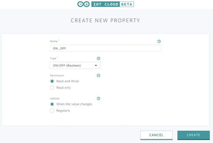
We start by going back to the property settings of our thing to add a new property, which we will call ON_OFF. It will be of type “ON / OFF (boolean)” and will have the read and write permission, with updates taking place only when there is a change in the value.
With this done, the property should now be listed on our widget along with the others as shown below.
Click on the “edit code” button, the code with the recent changes will be generated and just as we did with the last one, we will add our own bits to it, to display the text on the RGB Shield.
To make it easy to follow, we will remove the environment variables of Part 1 from the generated code leaving only the code required for this part.
As usual, the sketch starts with the inclusion of the required libraries and header files. In addition to the header files included by the IoT Cloud, we add the Arduino Graphics library and the Arduino MKR RGB librarywhich are both required to simplify the code for the RGB shield.
With this done, we move to the void setup() function.
We start by initializing serial communication, setting the baud rate to 9600 and then initializing the parameters defined in the thingproperties.h header file with the initProperties() function.
void setup() {
// Initialize serial and wait for port to open:
Serial.begin(9600);
// This delay gives the chance to wait for a Serial Monitor without blocking if none is found
delay(1500);
// Defined in thingProperties.h
initProperties();
Next, we connect to the Arduino IoT Cloud using the ArduinoCloud.begin() function with “ArduinoIoTPreferredConnection” variable as an argument. This variable has been already set to a WiFi connection in the “thingproperties” header files.
// Connect to Arduino IoT Cloud
ArduinoCloud.begin(ArduinoIoTPreferredConnection);
After this, we initialize the RGB LED Matrix using the MATRIX.begin() function after which we set the brightness, text scroll speed and clear it.
MATRIX.begin();
// set the brightness, supported values are 0 - 255
MATRIX.brightness(200);
// configure the text scroll speed
MATRIX.textScrollSpeed(125);
MATRIX.clear();
MATRIX.endDraw();
with that done, just like with Part1, we end the code by setting the debug message level and printing debug info.
With this done, we move to the void loop() function. We start by sending an update request to the cloud and checking if the value of the state variable has changed. If the value of the state variable has changed to 1, the RGB is cleared, cursor set, the “ON” text displayed using the Matrix.print() function and it is instructed to scroll.
void loop() {
ArduinoCloud.update();
if (state == 1)
{
MATRIX.clear();
MATRIX.endDraw();
MATRIX.beginText(0, 0, 0, 127, 0); // X, Y, then R, G, B
MATRIX.print(" ON");
MATRIX.endText(SCROLL_LEFT);
If the state is 0, the display is cleared and the “OFF” text is displayed using the same functions as above.
}else if (state == 0) {
MATRIX.clear();
MATRIX.endDraw();
MATRIX.beginText(0, 0, 127, 0, 0); // X, Y, then R, G, B
MATRIX.print(" OFF");
MATRIX.endText(SCROLL_LEFT);
}
In case the system is unable to ascertain the value of the state variable for any reason, a blank screen is displayed by wiping the RGB LED Display.
else{
MATRIX.clear();
MATRIX.endDraw();
}
Lastly, for debug purposes, the state value is printed on the serial monitor.
Serial.println(state);
}
After the void loop(), the function which handles the state value is written. As soon as an update is requested from the cloud, if there is a change in the value, the function updates the state variable with the change in value.
void onONOFFChange() {
if (ON_OFF == true)
state = 1;
else
state = 0;
}
The complete code is available below and also attached under the download section of the tutorial.
#include "arduino_secrets.h"
#include "thingProperties.h"
////////////////////////////////
#include <ArduinoGraphics.h> // Arduino_MKRRGB depends on ArduinoGraphics
#include <Arduino_MKRRGB.h>
////////////////////////////////
int debug = 0;
int state = 2;
void setup() {
// Initialize serial and wait for port to open:
Serial.begin(9600);
// This delay gives the chance to wait for a Serial Monitor without blocking if none is found
delay(1500);
// Defined in thingProperties.h
initProperties();

// Connect to Arduino IoT Cloud
ArduinoCloud.begin(ArduinoIoTPreferredConnection);
// initialize the display
MATRIX.begin();
// set the brightness, supported values are 0 - 255
MATRIX.brightness(200);
// configure the text scroll speed
MATRIX.textScrollSpeed(125);
MATRIX.clear();
MATRIX.endDraw();
/*
The following function allows you to obtain more information
related to the state of network and IoT Cloud connection and errors
the higher number the more granular information you’ll get.
The default is 0 (only errors).
Maximum is 4
*/
  setDebugMessageLevel(2);
  ArduinoCloud.printDebugInfo();

}
void loop() {

  ArduinoCloud.update();
  if (state == 1)
  {
    MATRIX.clear();
    MATRIX.endDraw();
    MATRIX.beginText(0, 0, 0, 127, 0); // X, Y, then R, G, B
    MATRIX.print(" ON");
    MATRIX.endText(SCROLL_LEFT);
}else if (state == 0) {
    MATRIX.clear();
    MATRIX.endDraw();
    MATRIX.beginText(0, 0, 127, 0, 0); // X, Y, then R, G, B
    MATRIX.print(" OFF");
    MATRIX.endText(SCROLL_LEFT);
}else{
MATRIX.clear();
MATRIX.endDraw();
}
   Serial.println(state);
}
void onONOFFChange() {

  if (ON_OFF == true)
    state = 1;
  else
    state = 0;

}
Demo
Just like we did for both the schematics and programming sections, we will also separate the demo into two parts as I believe you will most likely use the same MKR WiFi 1010 board for both parts.
Part 1 Demo
At this stage, we are ready to upload the code to the Arduino MKR WiFi 1010 board. Double check the connections between the Arduino and TFT LCD, and ensure the ENV shield is well plugged in. Also, check to ensure you have filled the credentials for the WiFi access point in the Arduino_secrets.h file.
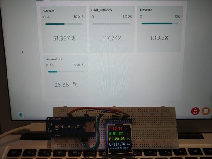
With the board plugged in as when you generated the code, upload the code to your board. You can launch the serial monitor to see how things are going. After a few seconds, you should see the MKR WiFi 101o connect to the Internet through the WiFi access point and you should see data being displayed on the widget page of the “thing” we created and also on the TFT as shown in the image below.
Part 2 Demo
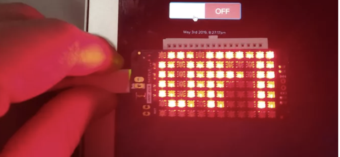
For the Part 2, Plug in the MKR RGB Shield into the MKR WiFi 1010 board as described under the schematics section and double check to ensure you have filled the credentials for the WiFi access point in the Arduino_Secrets.h file. The Arduino_secrets.h file can be found in the same folder as the code generated from the IoT Cloud. With everything in place, upload the code to the board and toggle the switch on the Widget page of the Arduino IoT Cloud. You should see the text on being displayed on the RGB switch between “on” and “off’ depending on the state of the switch widget.
It is important to note that you can combine both sketches to build a system capable of two way communication with the IoT Cloud. We just separated things so as to be able to explain the steps in details. As a learning challenge, you can try combining the code for both parts or creating a similar project and testing it out. That’s it for today’s tutorial, feel free to reach out to me via the comment section with questions and any general comment about today’s project.
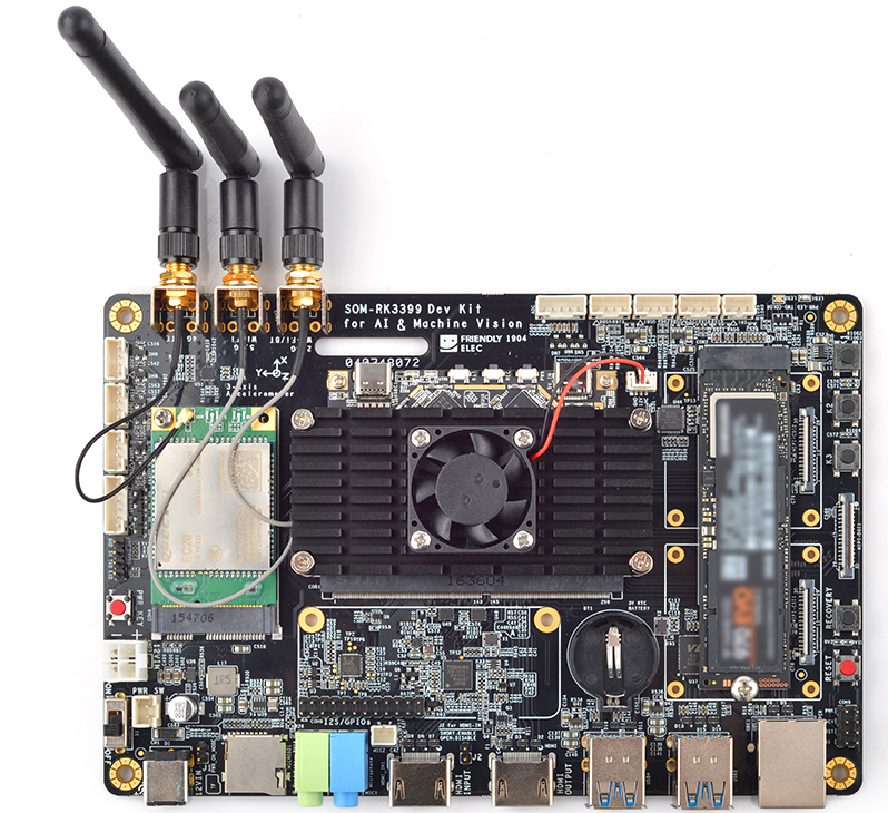
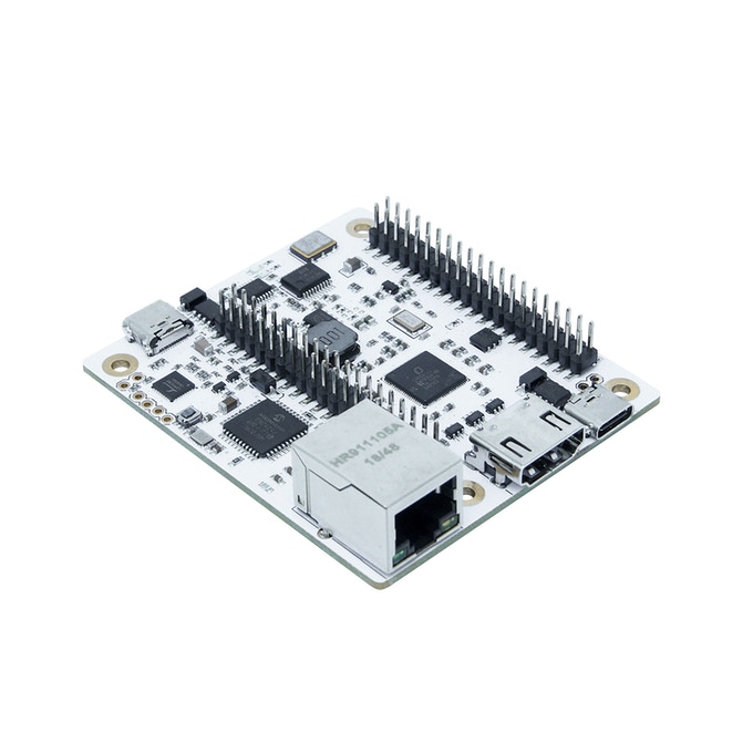
FriendlyElec has launched a new SOM-RK3399 and SoM-RK3399 Development Kit based on Rockchip’s powerful SoC and aimed at AI and computer vision applications. The s $75, RK3399-based “SOM-RK3399” COM/SBC hybrid can function alone or can be expanded with a $120 “SOM-RK3399 Dev Kit” with -20 to 70℃ support and M.2 and mini-PCIe expansion.
FriendlyElec Dev Kit
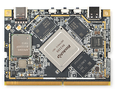
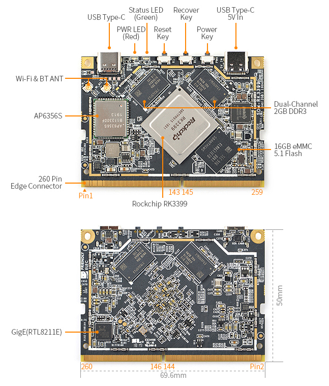
Last year, the company released a pair of open source SBCs built around the same chip, the NanoPi M4, also with the NanoPi Neo4, expected to take on the Raspberry Pi 3 with its less powerful Broadcom BCM2837 SoC. On the CPU board feature, the SOM-RK3399 can run as an independent SBC, and beyond the 64-bit hexa-core RK3399 with Mali-T864 GPU, the board is equipped with 2Gb of dual-channel DDR3 RAM, and 16Gb (32Gb/64Gb optional) of eMMC 5.1 Flash. Connectivity features include Gigabit Ethernet, 802.11a/b/g/n/ac Wi-Fi, Bluetooth 4.1 (dual mode), and a dual antenna interface. The SOM-RK3399 is fitted with a pair of USB Type-C ports, 2X USB 2.o ports, a single USB 3.0 host interface, HDMI 2.0a, Display Port (over USB Type-C), a 4-lane LCD eDP connector, and one or two 4-Lane MIPI-DSI.
SOM-RK3399 as a Standalone
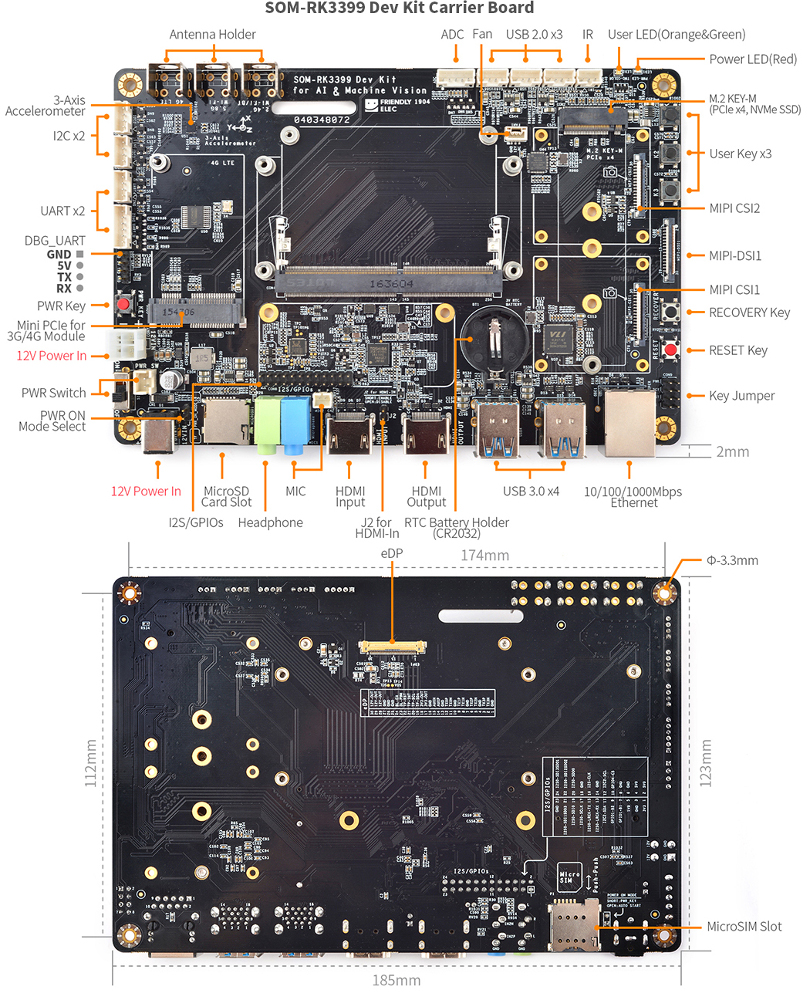
Available also are PCIe X4 (compatible with PCIe 2.1/dual-mode operation), plus 14X GPIO (6X 1.8V/8X 3.3V), I2S, 2X I2C (1.8V/3.3V), 2X PWM, UART / SPI, ADC, IR-RX, SPDIF_TX, and 3X 1.8V ADC inputs. FriendlyElec’s SOM-RK3399 DEV Kit Carrier Board features an M.2 slot for NVMe-style SSDs and a mini-PCIe slot for connecting 4G/LTE modules. It also has MIPI CS12/MIPI-DSI1/MIPI CSI1 connectors, 4X USB 3.0 ports, 3X USB 2.0 4-pin connectors, HDMI Input/output ports, mic/headphone jacks, IR/accelerometer, and a micro SD card slot.
The Carrier Board’s also features a 10/100/1000mbps Ethernet port, 3X antenna connectors, and a host of different headers — 3X ADC, IR-IN, 2X I2C, 2X UART, 8ch-I2S, 3X GPIO, and 1X SPDIF-TX. The SOM-RK3399 Development Kit OS option takes advantage of Android 7.1 with RKMC (Kodi), Android 8.1 with NN SDK (for leveraging GPU acceleration for AI applications), Ubuntu 16.04, FriendlyCore 18.04, and Armbian.
FirendlyElec prices the SOM-RK3399 standalone SBC Board for $75 or packaged with the Carrier Board for $120. There is also a host of add-ons as well, such as various-sized touchscreen displays, MIPI camera modules, and more.
Specifications listed for the new SOM-RK3399 Dev Kit include:
Processor (via SOM-RK3399) — Rockchip RK3399 (2x Cortex-A72 at up to 2.0GHz, 4x Cortex-A53) with Mali-T860 GPU
Memory/storage: 2GB DDR3 RAM (via SOM-RK3399), 16GB, 32GB, or 64GB eMMC 5.1 (via SOM-RK3399), MicroSD slot, Optional NVMe SSD via M.2 M-key (see below)
Networking: GbE port (native), 802.11b/g/n/ac (2×2 MIMO) with Bluetooth 4.1 (Ampak AP6356S, via SOM-RK3399), 3x antenna interfaces with optional antennas
Media I/O: HDMI 2.0a port for up to 4K@60Hz, HDCP 2.2, HDMI input, DisplayPort 1.2 available via USB Type-C, eDP 1.3 (4-lane), MIPI-DSI (1x or 2x 4-lane), MIPI-CSI (1x or 2x 4-lane) for up to 13MP cameras, Optional 7-inch, 1280 x 800 or 11.6-inch, 1920 x 1280 cap touchscreen, Optional cameras, Dual display support, 2x audio jacks, SPDIF and I2S interfaces
Other I/O: 2x USB 3.0 Type-C ports, 1x for power, 1x for USB or DP 1.2 (via SOM-RK3399), 4x USB 3.0 host ports, 3x USB 2.0 interfaces, 2x I2C, 2x UART, Debug UART, ADC, fan header, SPI, PWM, GPIO, etc.
Expansion: Mini-PCIe slot with 4G/LTE support, Micro-SIM slot, M.2 M-key with PCIe x4 and NVMe SSD support
Other features: Recovery, reset, power keys and 2x LEDs (via SOM-RK3399), 3x LEDs, Power key, switch, mode select, key jumper, reset key, recovery key, 3x user keys, IR receiver, 3x axis accelerometer, Multiple LEDs, Cooling fan (possibly optional)
Power: 2x 12V DC inputs (jack and connector); USB Type-C; RK808-D PMIC; DC 12V/1A connector on SOM-RK3399 module
Weight — 17.95 gm
Dimensions — 235.1 x 156.4 x 1.2mm, 8-layer (69.6 x 50mm for SOM-RK3399 module)
Operating temperature — -20 to 70℃
Operating system — Linux 4.4-LTS with U-boot, Android 7.1 with RKMC (Kodi), Android 8.1 with NN SDK, Lubuntu 16.04, FriendlyCore 18.04 with Qt 5.1 and OpenCV4, FriendlyDesktop 18.04 with Qt 5.1 and OpenCV4, Buildroot
Torex Semiconductor Ltd. has launched the XC6193/XC6194 as new series of Push Button.
In recent years there have been strong calls for power conservation of IoT and wearable devices and demand to increase operation time. Torex is proposing the XC6193/XC6194 to solve these problems.
This IC is push button load switch that greatly reduces the power consumed during post-load wait and when power is off and allows the power to be shut down when there is a system freeze. It also contributes to device energy conservation and longer operation time. When the main power is turned off to conserve power, the device power can be conserved by the microcomputer entering the Deep Sleep Mode or by using microcomputer and external components (discrete) to switch the power on and off. This IC does not require external components and just the IC is used to turn the power line on and off. In addition, the power line is shut down (OFF) after the shipment test of devices with built-in batteries to greatly reduce the power consumption when the device is stored for a long time. The current consumed when the power off is just 1nA (TYP.), which is very low consumption. When a system freeze has occurred and you want to compulsorily turn off the power, it cannot be done with a device that turns the system (microcomputer) power on and off, but using this IC the system (microcomputer) can be independently operated to surely turn off the power.
The XC6193 Series uses an external Pch MOSFET in addition to the built-in high side switch, so it can be used as a large current load switch.
The XC6194 Series has a built-in PG (Power Good) terminal and a built-in function for monitoring power start up.
These ICs are also equipped with an inrush current prevention soft start function and output short-circuit protection function to realize an intelligent load switch
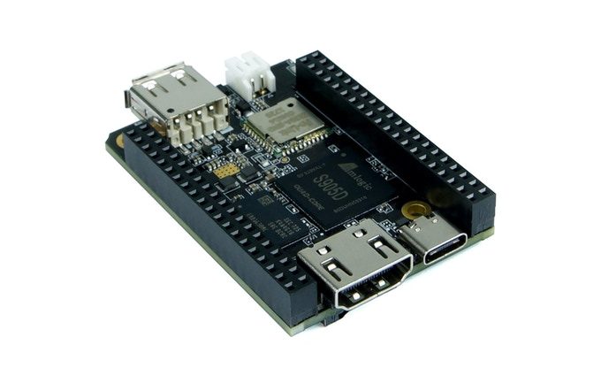
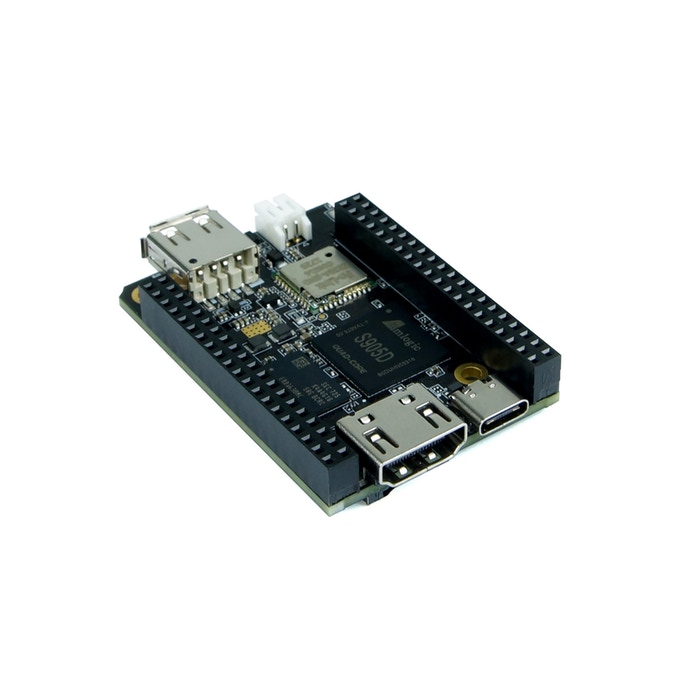
The world’s fastest 100% open-source hardware single-board computer.
Popcorn Computer is a next generation single-board computer brand. They would like to present the result of two years of effort by Source Parts, two brand-new and unique open hardware computers: Original Popcorn and Super Popcorn.
Super Popcorn
It comes in two flavors, one with 4 CPUs, Super Popcorn, and another with 8 CPUs which we call ‘Super 8′ Popcorn.
Detailed Specifications:
Super Popcorn and Super ‘8’ Popcorn share many of the same specifications.
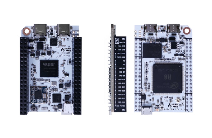
In addition to Super Popcorn, we created a C.H.I.P derivative named Original Popcorn Computer. Original Popcorn is pin-to-pin compatible and 100% software compatible with C.H.I.P. With USB-C Technology, you will have all the power to do what you want to do while keeping the lights on. It has built-in eMMC memory that is reliable, fast and tested to work which means you don’t have to go searching for the right SD card. It has a built-in USB Serial adapter so you can quickly debug without having to grab the right adapter and connect wires. If you already own a PocketC.H.I.P, you can give it an upgrade with Original Popcorn.
Detailed Specifications:
Allwinner R8/A13 1GHz CPU
512MB DDR3 RAM
32GB eMMC Memory Storage
2x USB-C Connectors (1x USB 2.0 and 1x USB OTG)
WiFi b/g/n with Bluetooth 4.0
Up to 45 GPIO
Composite Video Output
Battery Charging and Power
Built-in USB Serial Adapter
Analog Audio over USB-C Connector
Supports RGB LCD, 1-Wire, UART, I2C, SPI and PWM Output
Stovetop
Original Popcorn also has a companion board. Meet Stovetop! It takes its namesake from the idea that you can cook your Popcorn ideas on the Stovetop. It provides HDMI Video output with Audio, 100Mbit Ethernet, USB-C Power Input and a USB-C Serial Debug connector. It is essential for anyone who is more familiar developing with a graphical environment compared to a command-line based environment.
Further information
The $49 Original Popcorn, $69 Super Popcorn, $89 Super 8 Popcorn, and $39 Stovetop add-on for the Original are available on Kickstarter through June 27, with shipments expected in November. More information may be found on Source Parts’ Popcorn Kickstarter page.
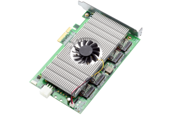
AAEON, an award-winning leader of AI edge solutions, announces the latest products in our line of AI modules featuring the Intel Movidius Myriad X, the AI Core XP4 and XP8. The AI Core XP4 and XP8 offer users a scalable solution on a PCIe [x4] form factor for PC-based AI applications and neural network acceleration.
While most PCs are capable of handling AI applications, the computations required are often quite complex and data intensive, limiting the speed at which the AI inference can operate, or slowing down performance of other applications which must run simultaneously. The AI Core XP4 and XP8 allow users to offload the AI inference from the main CPU processor, speeding up AI processing, and freeing the CPU to handle other important tasks.
The AI Core XP4 and XP8 feature four (XP4) or eight (XP8) Intel Movidius Myriad X VPUs. Each Intel Myriad X VPU is capable of speeds up to 105 fps (80 typical) and up to 1 trillion floating point operations as a dedicated neural network. This means a performance of up to 840 fps (560 typical) with the AI Core XP8, providing incredible processing power for your AI applications.
The AI Core XP4 and XP8 bring users scalability not offered on any other PCIe based AI module card. While other cards are designed with VPUs soldered directly onto the boards, the AI Core XP4 and XP8 are designed by combining two to four AI Core XM 2280 modules onto a single card. This means the AI Core XP4 and XP8 feature four M.2 slots, allowing users the ability to scale the capabilities of the card to match their needs. Users can easily add an additional AI Core XM 2280 module to the AI Core XP4 giving the power of six Intel Myriad X VPUs. This scalability is perfect for users whose processing needs may change over time, or are unsure exactly how much performance they need; providing the option to change the power available without having to buy an entire new card.
As with all of our award winning products, AAEON offers manufacturer service for customers who have exact needs, providing support in finding and developing solutions to fit your needs. The AI Core XP4 and XP8 bring more flexibility and scalability to our innovative line of AI Core X modules featuring Intel Myriad X, and provides a powerful solution for PC-based AI edge applications.
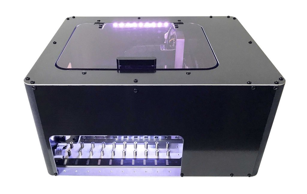
Hong Kong-based Amoeba Robotics is set to launch a pick and place machine for engineers, designers, and makers to conveniently automate the assembly of their PCBs ontop of their desks, with a more affordable price range going for $1,950. This is incredible because most pick and place machines are incredibly expensive, with the desktop models running into thousands of dollars or more.
Founded in 2010, Amoeba Robotics is a Hong Kong-based research, engineering, and design company that focuses on advanced robotics and automation. The company says that their Boarditto is suitable for rapid prototyping and small-batch manufacturing, boasting of more than 15 components placed per minute. The device has an extensive feature set for a desktop machine and includes a dual camera setup, one above, and one below, which automatically detects fiducial markers that compensate for PCB misalignment, and corrects the position of each component during the pick and place process. Users have the option of up to 16 feeders loaded at any time and supports both JEDEC and custom trays.
The Boarditto doesn’t need a connection to the internet to function, this is due to its built-in computer (no specifics as to type), enabling you to add a monitor, keyboard, and mouse to program the machine using the Boarditto V1.0 app. “Amoeba” equipped the pick and place machine with a built-in vacuum pump to keep things neat, also has an automatic nozzle changer, and can accept PCBs at up to 160mm x 100mm.
Video
The Boarditto helps to free up your time and energy by leaving the repetitive task of assembling PCBs to a machine. It also helps in avoiding inaccuracies and mistakes that can easily occur when hand-soldering, such as bridging pins of fine-pitched components or placing a component on the wrong spot. Amoeba Robotics is currently accepting pre-orders for the Boarditto, and also some add-ons — including automatic tape feeders ($95), manual tape feeders ($20), aluminum tray holders ($190), and a soon-to-be-released “dittoReal,” which appears to be a giant part dispenser. If you pre-order before June 15, Amoeba will include a pair of auto-feeders and manual feeders free of charge.